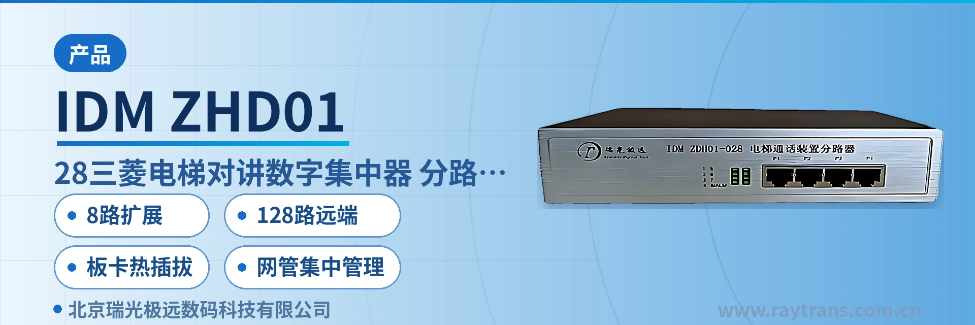
IDM ZHD01-028 Elevator Intercom Digital Concentrator
Optical multiplexer low-level signal plus one-stage audio enhancement; 8-channel board expands to 128 channels; 12 boards hot-swappable
The IDM ZHD01-028 elevator intercom digital concentrator (also called an elevator intercom splitter) is a dedicated concentration device used together with the ZHD01-006 local intercom call interruption device. It enables: 1. one Mitsubishi intercom master unit to interconnect with more remote devices; 2.
IDM ZHD01-028 Mitsubishi elevator intercom digital concentrator (also called elevator intercom splitter) is an elevator intercom concentration device developed by Beijing Ruiguang Jiyuan Digital Technology Co., Ltd. (Raytrans). It is used together with the ZHD01-006 local intercom call device to interconnect one Mitsubishi intercom master unit with more remote elevator intercom devices, and also to extend the transmission distance of remote devices. It is a supporting device for product showcase and centralized management on the elevator terminal side.
When elevator intercom signals are carried over optical fiber and the signal output by the optical multiplexer has low impedance and small amplitude, adding one stage of concentrator on the link can improve the voice transmission effect. The concentrator also expands the branches so that one master unit can serve more remote devices, and disconnects unused audio channels. As a supporting product of an optical multiplexer manufacturer and a media converter manufacturer, this type of concentrator from Raytrans can also be incorporated into smart mining communication solutions and government private network optical fiber communication solutions, performing the role of signal aggregation and product showcase for elevator terminals.
Key Specifications at a Glance: 8-channel expansion per board · 12 hot-swappable boards in parallel · 128 interfaces · independent number per branch · mobile phone Bluetooth configuration · 5V power supply
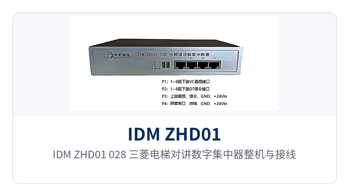
Figure 1: IDM ZHD01-028 Mitsubishi elevator intercom digital concentrator unit and wiring positions
Why add one stage in the optical fiber link for a Mitsubishi elevator intercom digital concentrator?
Traditional elevator intercom uses twisted pair, with multiple elevators connected directly in parallel at the central end, usually no more than 10 in parallel; when the number increases further, a 1-to-8 concentrator is used, with each downstream interface connected to six or seven remote devices. In the copper cable era, the links were short and the levels high, so multiple parallel connections could still maintain calls.
After elevator intercom is carried over optical fiber, this premise changes. The signal output by the optical multiplexer has low impedance and small amplitude, and the signal level drops from about 10V to 2~3V, so continuing to use the original concentrator for multiple parallel connections becomes unstable; as a key node on the elevator terminal link, capacity expansion of the elevator intercom concentrator requires channel management at this stage, disconnecting audio channels that are not in use to reduce audio line loss.
Optical fiber also isolates the voltage and current paths at both ends of the twisted pair. The concentrator detects voltage and current changes at the electrical interface, sends the changes to the interface at the other end and restores them, so that the intercom master unit can identify the call, busy line and hang-up state of each extension, while the signaling interface provides idle and busy line status indication.
How are 8-channel expansion per board and 128 remote interfaces built up?
Expansion starts from one board. One board supports expansion from 1 to 8 channels, and each expansion port can connect multiple elevators; 8 channels is only the number of branches, not the upper limit of elevators that can be connected; boards support parallel connection, and any number of boards in parallel does not affect system performance, so capacity can be expanded by adding boards according to the number of elevators on site.
The centralized chassis makes parallel connection a maintainable structure. When the IDM-120N chassis is used, 12 boards are hot-swappable, that is, 128 remote interfaces are supported, and replacing a single board does not require powering down the whole unit; when the centralized chassis is used, centralized network management is supported, and board and branch status can be viewed uniformly on the network management side.
Multi-level system cascading is also available, moving the aggregation point forward to the building or equipment room, avoiding direct parallel connection on twisted pair as far as possible, so that signal transmission performance is better guaranteed. During networking, calculate the required number of branches according to the number of elevator groups and the number of remote devices in each group, then convert this into the number of boards and chassis slots.
| Configuration | Number of boards | Remote interfaces | Management and maintenance |
|---|---|---|---|
| Single board working independently | 1 | 8 | Mobile phone Bluetooth on-site configuration, no chassis required |
| Multiple boards in parallel | In parallel as required | 8 × number of boards | Parallel connection does not affect system performance |
| IDM-120N centralized chassis | 12 | 128 | Hot-swappable board replacement, centralized network management |
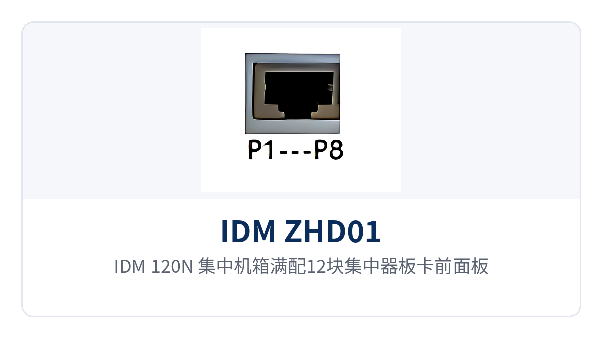
Figure 2: Front panel of an IDM-120N centralized chassis fully configured with 12 concentrator boards
How is precise addressing achieved with independent number configuration per branch interface?
Each branch interface can be independently configured with the number of the terminal connected to it, and addressing follows the branch rather than mixing devices on the entire line into one address pool. The number plan corresponds to the address table of the elevator master unit, so one master unit can accurately call a specific elevator without crossing to other branches in the same group.
Number configuration is done locally. A single board can work independently and be configured on a mobile phone through the Bluetooth interface, so on-site commissioning does not require a chassis or a laptop; boards in the centralized chassis are also checked branch by branch, and all numbers are verified at one time before the equipment is put into operation.
Address planning should leave margin; before capacity expansion, define the address segment first and then add boards. Limited by the system address settings, a single system can support up to 250 elevator intercom channels, and the actual number of available channels is subject to the master unit address table and on-site configuration; before adding boards, incorporate the numbers of new branches into the same address segment to avoid conflicts with existing numbers.
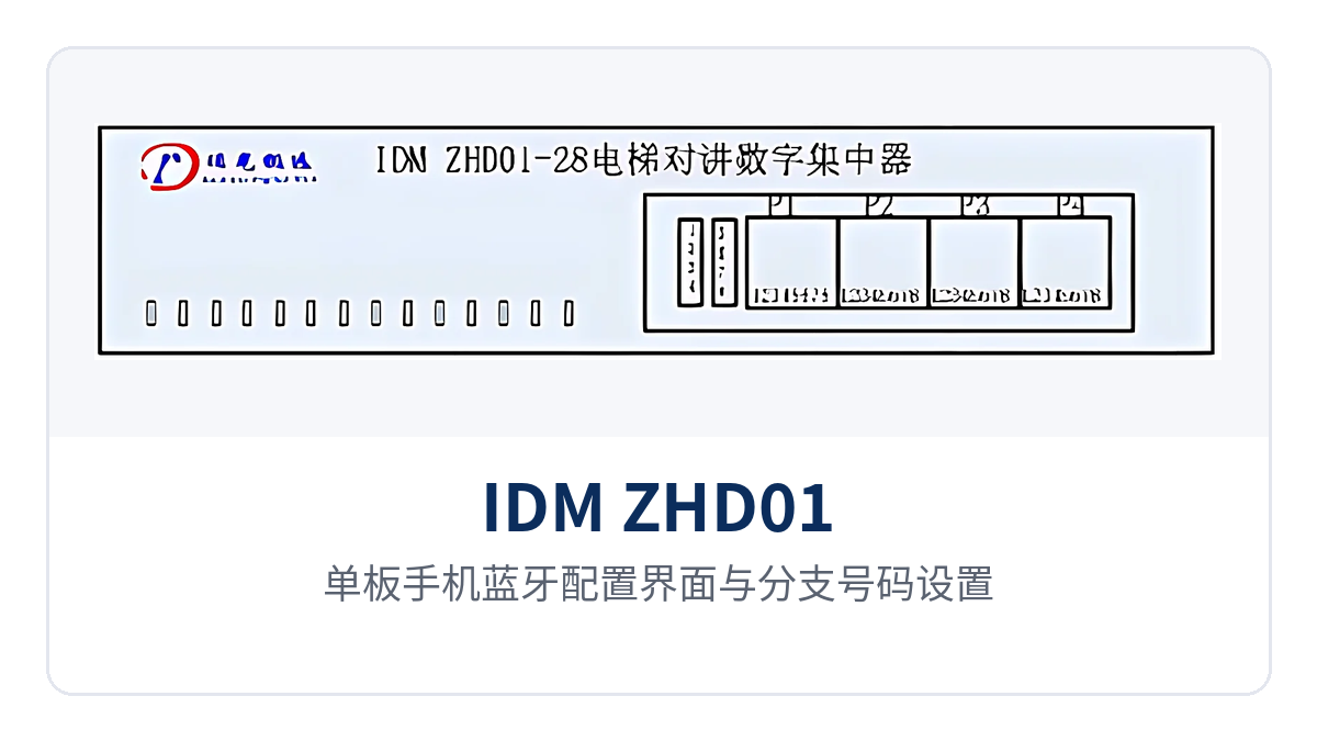
Figure 3: Single-board mobile phone Bluetooth configuration interface and branch number settings
How to wire: P1, P2, P3 and P4 interfaces and pin definitions
The device side is divided into four groups of interfaces: P1 is the downstream audio interface, P2 is the downstream signaling interface, P3 is the upstream interface, and P4 is the network management interface. The downstream side connects to each elevator branch, the upstream side connects to the intercom master unit side or the optical multiplexer side, the network management interface provides an RS232 serial port, and the device is powered by a 5V power supply.
| Interface | Purpose | Pin definition |
|---|---|---|
| P1 | Downstream audio | Pin1 to Pin8 correspond to audio channels 1 to 8 |
| P2 | Downstream signaling | Pin1 is signaling DT for channel 1, Pin2 to Pin8 correspond to signaling for channels 2 to 8 |
| P3 | Upstream interface | Pin1 upstream audio, Pin2 upstream signaling, Pin3 to Pin6 upstream and downstream analog common ground GND, Pin7 and Pin8 are +24V interface level inputs |
| P4 | Network management interface | Pin1 RS232 serial transmit TX, Pin2 RS232 serial receive RX, Pin3 reserved, Pin4 serial common ground GND, Pin5 and Pin6 upstream and downstream analog common ground GND, Pin7 and Pin8 are +24V interface level inputs |
Pin2 to Pin8 of P2 are arranged as channels 2 to 8 in the original factory wiring documentation; before on-site work, check against the supplied wiring diagram and the wiring sequence confirmed with the manufacturer to avoid reversing audio and signaling. When connecting the upstream side to the optical multiplexer and intercom master unit, route audio, signaling and ground wires in groups, and power on only after the connectors are securely fastened.
When inserting boards into the centralized chassis, first confirm that the slot matches the branch number, then check channel by channel against the number table; when a single board is used independently, match the branches according to the panel markings and wiring diagram, and connect the master unit side after number configuration. After wiring is complete, first perform a single-branch call test, then connect the branches one by one.
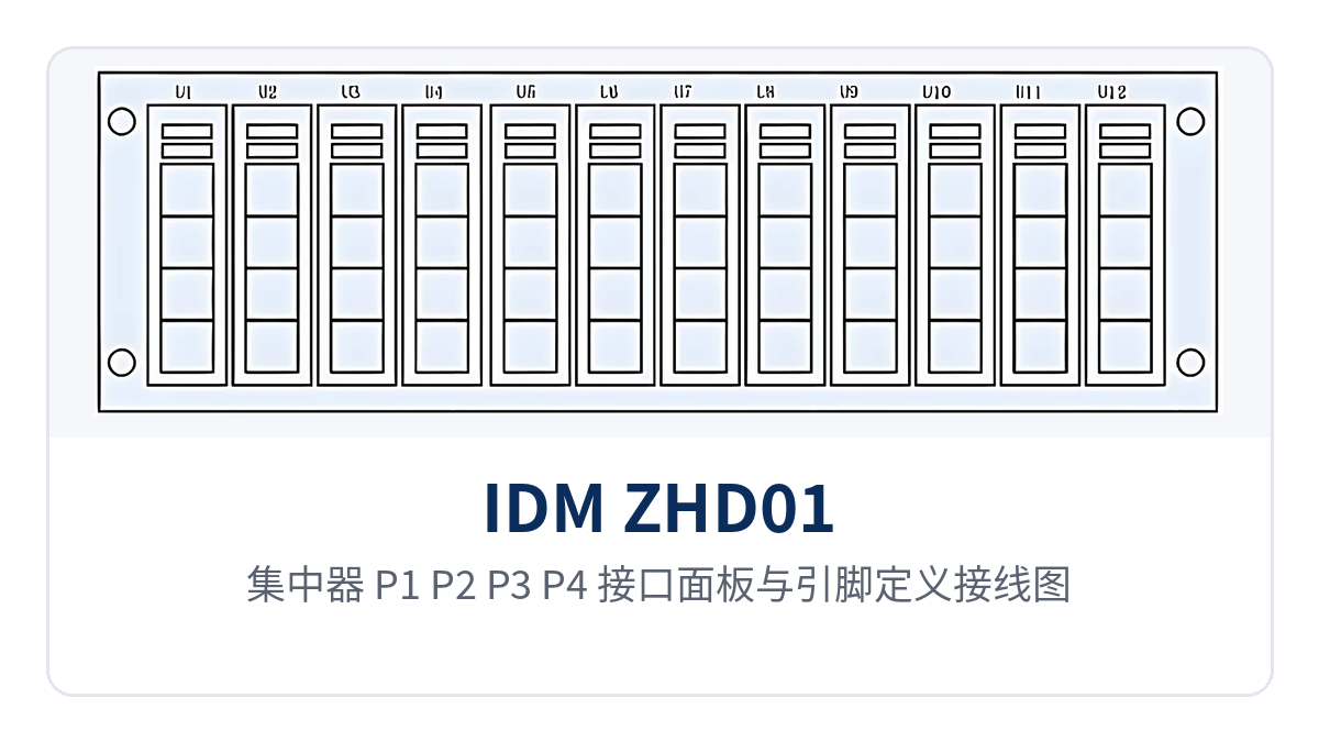
Figure 4: Concentrator P1, P2, P3 and P4 interface panel and pin definition wiring diagram
Core Functions and Technical Specifications
Core Functions
| Function | Description |
|---|---|
| 8-channel expansion | A single board supports expansion from 1 to 8 channels, and each expansion port can connect multiple elevators |
| Multiple boards in parallel and hot-swappable boards | Any number of boards in parallel does not affect system performance; the IDM-120N chassis supports 12 hot-swappable boards |
| 128 interfaces | 12 boards in parallel provide 128 remote interfaces |
| Independent branch numbering | Each branch interface is independently configured with the number of the connected terminal for precise addressing |
| Bluetooth mobile phone configuration | A single board working independently can be configured on a mobile phone through the Bluetooth interface |
| Centralized network management | Centralized network management is supported when the centralized chassis is used, and P4 provides an RS232 serial port |
| Signaling level detection and control | Performs level detection and control on the signaling interface and provides idle and busy line status indication |
| Signaling message forwarding | Receives and forwards intercom signaling messages, converting the messages from audio transmission to the data interface |
| Idle channel disconnection | Switches intercom audio channels so that unused channels are no longer connected in parallel to the line, reducing audio line loss |
| Multi-level system cascading | Supports multi-level system cascading, avoiding the impact of direct parallel connection on twisted pair on signal transmission performance |
| Voice quality improvement | Compensates for the low-impedance, small-amplitude signal output by the optical multiplexer and improves the voice transmission effect |
Technical Specifications
| Item | Parameter/Specification | Description/Applicable Conditions |
|---|---|---|
| Product name | IDM ZHD01-028 Mitsubishi elevator intercom digital concentrator (elevator intercom splitter) | Used together with the ZHD01-006 local intercom call device |
| Power supply | 5V | The device is powered by a 5V power supply |
| Expansion capability | 1 to 8 channels per board, each expansion port can connect multiple elevators | The number of branches is planned according to the number of elevators on site |
| Parallel connection and chassis | Any number of boards in parallel; 12 hot-swappable boards in the IDM-120N chassis | A fully configured chassis supports 128 remote interfaces |
| Remote interfaces | 128 | Number of remote interfaces when the IDM-120N centralized chassis is fully configured with 12 boards |
| Branch numbering | Each branch interface is independently configured with a terminal number | The number corresponds to the intercom master unit address table |
| Configuration method | Mobile phone Bluetooth (single board), RS232 network management (centralized chassis) | On-site commissioning does not need to wait for the chassis to arrive |
| System addressing | A single system can support up to 250 elevator intercom channels | Limited by the master unit address settings, subject to on-site configuration |
| Downstream audio interface | P1, Pin1 to Pin8, 8 channels in total | Each channel corresponds to one elevator branch |
| Downstream signaling interface | P2, Pin1 to Pin8 | Pin1 is signaling DT for channel 1 |
| Upstream interface | P3, including audio, signaling, GND and +24V level input | Connects to the master unit side or the optical multiplexer side |
| Network management interface | P4, RS232 TX/RX/GND | Serial port centralized management |
| Status indication | Idle and busy line status indication | Provided by signaling interface level detection |
Differentiation Points
| Differentiation Point | Value Description |
|---|---|
| 8-channel expansion per board | One branch port can connect multiple elevators, and capacity is expanded by adding boards according to elevator groups, without configuring equipment per elevator |
| 12 hot-swappable boards in parallel | A fully configured IDM-120N chassis provides 128 remote interfaces, and replacing a single board does not require powering down the whole unit |
| Independent terminal number configuration per branch interface | Numbers correspond one-to-one with the master unit address table, so calls are accurately routed to a specific elevator |
| Independent Bluetooth configuration per board | On-site commissioning requires no chassis or laptop, and boards in weak-current shafts can also be put into operation first |
Typical Application Scenarios
Elevator IoT integrator: intercom from dispersed equipment rooms converged into one network
Elevator machine rooms in residential communities are mostly on the top floor, while the monitoring room is set up in the lobby, the gatehouse of the industrial park or the surveillance center, and optical cables have often already been laid between the machine rooms. On the equipment room side, IDM ZHD01-028 is used as the elevator terminal access device to converge the intercom branches of multiple elevators onto one board, with multiple boards connected in parallel into the chassis, and then sent to the surveillance center over one optical fiber, so that the elevator Internet of Things (IoT) platform can locate the specific building and unit by branch number.
During commissioning, the integrator uses mobile phone Bluetooth to configure numbers for single boards without waiting for the centralized chassis to arrive, and boards in weak-current shafts can also be enabled first. When the community is expanded later, boards are added according to the number of elevators, branch numbers continue the existing address segment, and configuration changes on the platform side are minimal.
Rail transit private network communication: centralized access of elevator intercom in station halls and on platforms
Elevator groups and escalators are distributed across the concourses, platforms, and entrances of rail transit stations and airport terminals, intercom terminals are scattered across multiple equipment rooms, and the communications equipment room requires centralized access. IDM ZHD01-028 aggregates the branches on the equipment room side, and its 12-board hot-swappable enclosure provides up to 128 remote interfaces, making it suitable for large stations to consolidate within a single cabinet and easy to incorporate into a government private network optical fiber communication solution for unified planning.
Replacing a board during an operational window requires no power failure of the complete unit; after hot-swapping a single board, service is restored according to the original branch numbers, and calls on other branches are unaffected. On the network management side, board status is checked centrally through the RS232 serial port on the P4, and the duty operator dials the corresponding site by branch number; during troubleshooting, verify the number first, then check the line.
Industrial and Campus Private Networks: How to Plan Elevator Branches in a Weak-Current Shaft
Elevators in plants, industrial parks, and commercial complexes are arranged in groups, weak-current shaft space is limited, and centralized equipment must be placed close to the hoistway. The IDM ZHD01-028 board is compact and requires only 5V power supply; one board manages 8 branches, making it suitable for distributed placement by floor or building. Projects with many elevator groups can further use the IDM-120N enclosure for unified management.
Branch numbers are planned to correspond to buildings, units, and elevator numbers, with one line and one number on the construction drawings, so acceptance can be verified by dialing the number. The centralized chassis is placed in the weak-current room, and the network management interface connects to the existing surveillance network. Elevator intercom Bluetooth configuration and network management configuration complement each other, so O&M personnel do not need to open doors floor by floor to check wiring.
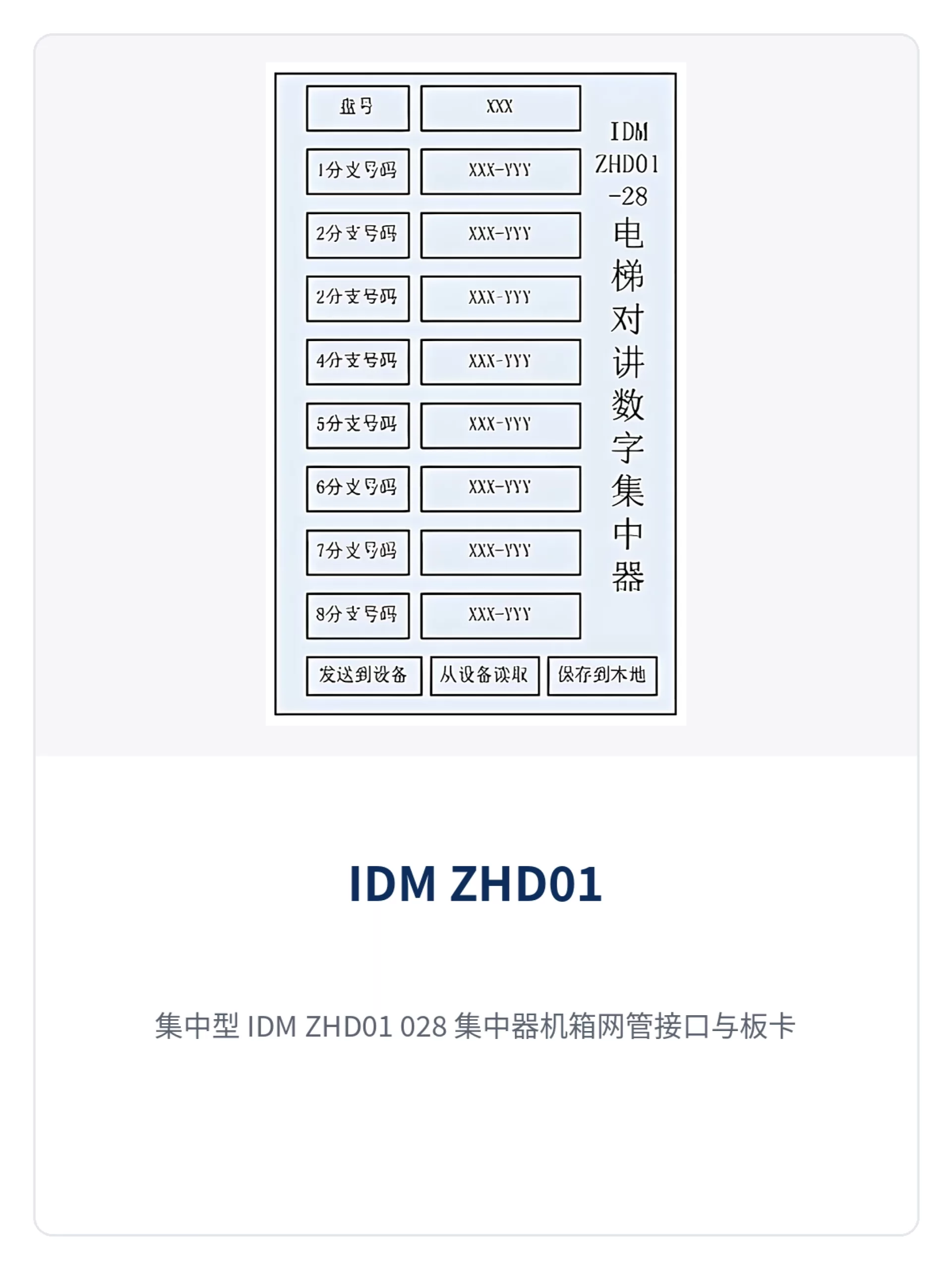
Figure 5: Close-up of the network management interface and board status indication on the centralized IDM ZHD01-028 concentrator chassis