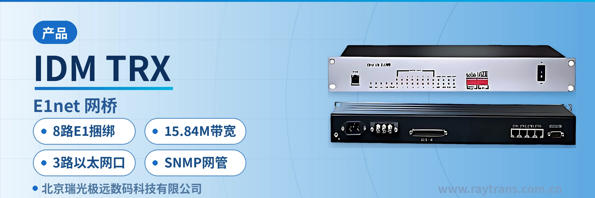
IDM TRX-8E1net Bridge
8-channel E1 inverse multiplexing, asymmetric receive/transmit channel counts, 220 ms delay difference tolerance
The IDM TRX-8E1net bridge is a protocol converter independently developed by our company using inverse multiplexing technology. The device bundles multiple E1 lines to transmit 10M/100M Ethernet data, converting between 8 E1 channels and Ethernet interfaces, with a maximum Ethernet transmission bandwidth of up to 15.84M.
The IDM TRX-8E1net bridge is an 8-channel E1 inverse multiplexing bridge, a protocol converter independently developed with inverse multiplexing technology, used to transmit 10M/100M Ethernet data over existing E1 channels. As a professional bridge converter, the device performs mutual conversion between 8 E1 channels and Ethernet interfaces, with Ethernet bandwidth up to 15.84M.
The IDM TRX-8E1net bridge targets LAN interconnection, central office interconnection, video on demand, remote surveillance, and E1 interface cards for switches, enabling the large number of existing E1 resources in telecommunications networks to directly carry Ethernet services. It is a typical application among E1 inverse multiplexing bridge products. For electric power private networks, rail transit, and military/government private networks, its value lies in extending Ethernet to sites covered by existing E1 channels without laying new optical cables for a single data link, which is precisely the pragmatic choice of the electric power private network E1 channel Ethernet transport solution; in government private network optical fiber communication solutions, such E1 inverse multiplexing bridges can also be used together with PCM equipment, optical multiplexing equipment, and optical multiplexers. As an optical multiplexer manufacturer and SDH equipment manufacturer, Raytrans continuously provides reliable product showcase and technical support for users of various private networks.
Key Specifications at a Glance: 8-channel E1 inverse multiplexing · 15.84M bandwidth · 3 Ethernet ports · 220ms delay difference · E1 bit rate 2048Kbps · SNMP network management
What Kind of Device Is an 8-Channel E1 Inverse Multiplexing Bridge?
Inverse multiplexing splits one Ethernet data stream into multiple data blocks in sequence, distributes them across multiple E1 links for parallel transmission, and the receiver reassembles the data blocks back into the original frames in sequence. A single E1 channel has a bit rate of 2048Kbps, and 8 E1 channels provide a total line capacity of about 16.384Mbps. This bridge converter is often classified under the E1 inverse multiplexing bridge category in product showcase, and is suitable for deployment in the same equipment room as PCM equipment and optical multiplexing equipment.
After deducting GFP-F encapsulation and link alignment overhead, the IDM TRX-8E1net bridge has a nominal Ethernet bandwidth of 15.84M, and its encapsulation format complies with ITU-T G.7041. The 8 E1 channels carry the same Ethernet service in sequence; if any E1 channel in the link becomes unavailable, the device automatically detects the number of available channels and allocates bandwidth according to the actual number of channels.
The E1 side supports configurable framed and unframed modes and configurable time slots, with a frame structure of PCM31/30, an impedance of 70 Ω (unbalanced) or 120 Ω (balanced), and HDB3 line coding. The interface complies with ITU-T G.703/G.704 recommendations, and jitter characteristics comply with ITU-T G.823. The Ethernet side provides 3 RJ45 electrical ports with selectable rates of 10M/100M, supports half-duplex and full-duplex operating modes, and complies with the IEEE802.3 standard.
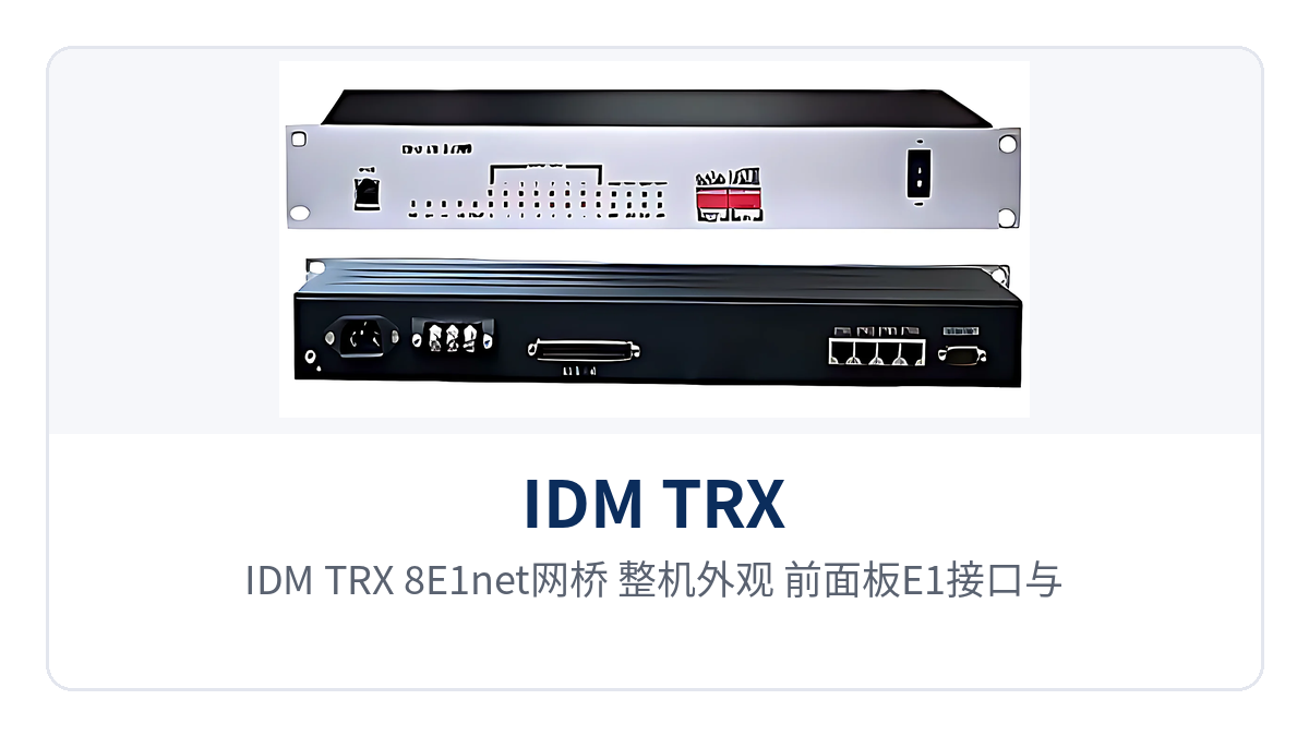
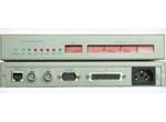
Figure 1: IDM TRX-8E1net bridge overall appearance, front panel E1 interfaces and 3 Ethernet ports
Core Functions and Their Effects
The functions of the IDM TRX-8E1net bridge focus on four aspects: inverse multiplexing and automatic bandwidth allocation, VLAN and long-frame transparent transmission, automatic handling of faulty channels, and line detection and network management monitoring. Each corresponds to an action verifiable on site. The table below lists functions and their effects row by row, so that during selection you can directly compare them with your service requirements and the conditions of the opposite-end device.
| Function | Description |
|---|---|
| 8-channel E1 inverse multiplexing | Implements inverse multiplexing of 3 electrical-port Ethernet channels to 8 E1 channels, bundling the 8 E1 channels into one logical link to jointly carry Ethernet services, with Ethernet bandwidth up to 15.84M. |
| Automatic detection of available channels | Automatically detects the number of available channels in the E1 lines and allocates bandwidth according to the actual number of available channels; when the number of channels changes, bandwidth adjusts accordingly without link interruption. |
| GFP-F encapsulation | Supports the GFP-F encapsulation format in compliance with ITU-T G.7041; Ethernet frames are encapsulated in sequence into E1 payloads and restored at the opposite end. |
| Non-corresponding E1 sequence numbers and asymmetric quantities | Supports applications with non-corresponding E1 sequence numbers in both receive and transmit directions and asymmetric E1 quantities; when the numbers of E1 channels at the two ends differ, services are carried according to the actual number of channels. |
| Inter-E1-line delay difference detection | Supports inter-E1-line delay difference detection; the relative delay tolerance between E1 lines is 220ms, so frames can still be reassembled in sequence when several E1 channels traverse different routes. |
| Automatic removal and recovery of E1 channels | Automatically removes E1 channels with alarms such as LOS, AIS, and LOF, and automatically recovers them after the fault disappears; services continue to be carried by the remaining channels. |
| TAG VLAN and long-frame transparent transmission | Supports TAG VLAN settings and can transparently transmit super-long frames specified by IEEE802.1Q, allowing direct connection to Ethernet switches with VLAN functions. |
| 2M line loopback | Supports the 2M line loopback function, which can be initiated locally to locate a fault section to the device side or the line side. |
| RS232 serial port and SNMP network management | Supports network management based on the RS232 serial port and SNMP, allowing monitoring of the device's operating status and setting of the device's operating state. |
Technical Specifications and Interface Specifications
Parameters are listed in three groups: E1 interfaces, Ethernet interfaces, and power supply environment. The table gives nominal values and applicable conditions; during on-site verification, the opposite-end transmission device and the accompanying technical documentation shall prevail. Operating temperature and storage temperature determine whether the device can be installed in an equipment room without air conditioning, while the humidity row relates to the risk of condensation.
| Item | Parameter/Specification | Description/Applicable Conditions |
|---|---|---|
| Number of E1 interfaces | 8 | Inverse multiplexing of 3 electrical-port Ethernet channels to 8 E1 channels; the numbers of channels at the two ends may be symmetric or asymmetric |
| E1 line coding | HDB3 | Interconnect with the 2M interfaces of existing PCM equipment and SDH transmission equipment |
| E1 bit rate | 2048Kbps±50ppm | Nominal rate per channel; about 16.384Mbps in total for 8 channels |
| E1 impedance | 70 Ω (unbalanced)/120 Ω (balanced) | Selected according to on-site cable and connector types |
| E1 frame structure | PCM31/30 | Framed/unframed configurable; time slots configurable |
| E1 signaling | Channel-associated signaling | Consistent with the signaling configuration of the opposite-end device |
| Jitter characteristics | Compliant with ITU-T G.823 | Basis for jitter tolerance of clock recovery after multi-stage transmission |
| Ethernet interfaces | 3 RJ45, 10M/100M selectable | Compliant with the IEEE802.3 standard; half/full duplex selectable |
| Ethernet bandwidth | 15.84M | Carrying bandwidth when 8 E1 channels are bundled at full configuration |
| Encapsulation format | GFP-F, compliant with ITU-T G.7041 | Encapsulation method of Ethernet frames in E1 links |
| E1 line delay tolerance | 220ms | Upper limit of relative delay for inter-E1-line delay difference detection |
| Network management | RS232 serial port, SNMP | Monitor operating status and set device parameters |
| Power supply mode | DC-48V/AC220V selectable | For both DC power supply and AC power supply environments in equipment rooms |
| Operating temperature | 15℃~+65℃ | Normal-temperature operating environment in equipment rooms and cabinets |
| Storage temperature | -25℃~+75℃ | Transportation and storage conditions |
| Relative humidity | 0~95% (non-condensing) | Condensation environments must be avoided |
Four Capability Tags: 8-Channel E1 Bundling, 15.84M Bandwidth, 3 Ethernet Ports, SNMP Network Management
In on-site discussions, the capabilities of this bridge are often summarized into four short tags; procurement, design, and O&M contacts can remember these four terms first. Below, each tag is explained in terms of its corresponding capability boundary and deployment conditions, as well as actions easily overlooked in actual configuration.
- 8-channel E1 bundling: Uses 8 E1 channels as one logical channel; bandwidth increases or decreases with the number of available E1 channels. Suitable for sites that only have E1 resources and where optical cables cannot reach for the time being.
- 15.84M bandwidth: The nominal Ethernet bandwidth after bundling 8 E1 channels at full configuration; can carry general data services such as office network interconnection, video on demand, and surveillance backhaul.
- 3 Ethernet ports: 3 RJ45 electrical ports can be accessed by service zone; one device connects the office network, video network, and management network simultaneously, saving an external switch.
- SNMP network management: Local configuration is completed through the RS232 serial port, and the device is incorporated into the SNMP NMS platform remotely, so E1 alarms and device operating status can be viewed centrally.
Typical Application Scenarios
The device is used mainly in three types of scenarios: electric power private networks, rail transit, and military/government private networks. Their common feature is that only E1 resources are available at the opposite end, while the service side uses standard Ethernet interfaces. Below, networking conditions and configuration points are described by industry, without involving specific project parameters. As typical deployment directions of the E1 inverse multiplexing bridge under Raytrans, these scenarios are also often used together with the existing transmission systems of optical multiplexer manufacturers and SDH equipment manufacturers.
Electric Power Private Networks: 8 E1 Channels Carrying Substation Ethernet Services
In electric power private networks, a batch of E1 channels usually already exists between substations, power supply stations, and the dispatching side, so new Ethernet services do not require dedicated optical cable laying. The IDM TRX-8E1net bridge bundles 8 E1 channels to carry Ethernet data; the 15.84M bandwidth can cover services such as message upload, records synchronization, and auxiliary surveillance, and only one bridge needs to be connected in series between the E1 patch panel and the service switch within the station. This deployment mode is precisely a typical implementation form of the electric power private network E1 channel Ethernet transport solution, and often serves as a supplementary section of government private network optical fiber communication solutions, completing service extension via existing E1 resources where optical cables do not yet reach.
When the 8 E1 channels are carried over different transmission routes, data blocks arrive at different times; the 220ms relative delay tolerance still allows the receiver to reassemble them in sequence. When an E1 channel has LOS, AIS, or LOF alarms, that channel is automatically removed, services continue to be carried by the remaining channels, and the channel automatically recovers after the alarms disappear, so Ethernet services at unattended sites do not require O&M personnel to attend on site.
Rail Transit: Ethernet Channels Between Stations Along the Line
In rail transit, E1 channels are usually laid along the line as existing transmission resources between stations along the line, section equipment rooms, and the line center. The IDM TRX-8E1net bridge performs inverse multiplexing of 8 E1 channels to provide an Ethernet channel for station integrated surveillance, passenger information, and office networks; the site side accesses standard RJ45 interfaces, and upper-layer network configurations need not be changed.
Links along rail lines pass through multiple stages of transmission equipment, so delay differences among the 8 E1 channels and alarms on individual channels are common operating conditions. The device supports inter-E1-line delay difference detection and automatically removes faulty channels and recovers them after restoration; the 2M line loopback function can initiate loopback at the station side to locate faults to the device or line section, shortening night maintenance windows.
Military and Government Private Networks: Revitalizing Existing E1 Resources and Avoiding Secondary Cabling
In military and government private networks, E1-based transmission channels have mostly been built between confidential sites, duty rooms, and superior authorities. The value of the IDM TRX-8E1net bridge is to revitalize these existing E1 resources into Ethernet channels; after inverse multiplexing of 8 E1 channels, it provides 15.84M bandwidth, and the 3 Ethernet ports can connect the service network, video conferencing, and management terminals respectively. In the overall architecture of government private network optical fiber communication solutions, such bridge converters play the role of edge access and service termination, complementing the transmission platforms of PCM equipment, optical multiplexing equipment, and SDH equipment manufacturers.
The reliability requirements of private networks ultimately rest on self-healing actions when channels fail. The IDM TRX-8E1net bridge automatically removes E1 channels with LOS, AIS, and LOF alarms and automatically recovers them after the faults disappear; scenarios with non-corresponding receive/transmit sequence numbers and asymmetric E1 quantities are also supported, and when the numbers of available E1 channels at the two ends differ, bandwidth is allocated according to the actual number of channels, so capacity expansion does not require synchronous modification of the entire link.
What to Pay Attention to in E1 Bridge Deployment and Wiring
On-site deployment is verified item by item according to cable impedance, parameter consistency at both ends, and uplink verification; typical symptoms when these items do not match are that the link cannot come up or services frequently flap. The sequence below combines configuration actions with verification actions, making it easy for the construction party and the O&M party to check item by item during handover.
- Cable and impedance matching: Select a 70 Ω unbalanced or 120 Ω balanced interface according to the on-site cable, and keep the connector type consistent with the transmission device at the opposite end.
- Parameter alignment at both ends: The PCM31/30 frame structure, framed/unframed mode, and time slot configuration must be identical at both ends; if one end is changed, the other end must be changed accordingly.
- Ethernet-side configuration: Connect the 3 RJ45 electrical ports by service zone, and match the 10M/100M rate and half/full-duplex mode to the switch at the opposite end.
- VLAN and long frames: When services with VLAN tags need to be transparently transmitted, enable the TAG VLAN setting and confirm that IEEE 802.1Q oversized frames can be transparently transmitted.
- Loopback and alarm check: Use a 2M line loopback to determine the fault section, and confirm that there are no persistent LOS, AIS, or LOF alarms before delivering services.
- Network management access: First complete the basic local-end parameters through the RS232 serial port, and then incorporate the device into the NMS platform through SNMP for unified monitoring.