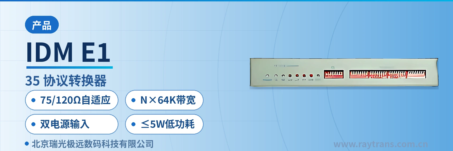
IDM-E1/V.35 Protocol Converter
Dual mode: transparent E1 and arbitrary time slot partitioning; unused time slots reserved for other services; transmit phase
The IDM-E1/V.35 interface converter and IDM-FE1/V.35 interface converter can convert all or part of the E1 time slots (i.e., N*64K) into a V.35 interface, with bandwidth from 64Kbps to 2048Kbps. They can be widely used in computer network interconnection and DDN data network access.
IDM-E1/V.35 is an E1-to-V.35 protocol converter developed by Beijing Ruiguang Jiyuan, used to convert all time slots of an E1 line, or any N of its 64K time slots, into one V.35 synchronous data interface, with the bandwidth set as required between 64Kbps and 2048Kbps. As a bridge converter product under Raytrans, the device is often presented together with access products such as PCM equipment in the product showcase.
One end of the device connects to the E1 transmission channel, and the other end connects via a DB25 connector to terminals with a V.35 port, such as routers, RTUs, and DDN nodes. Used in pairs, the two units open up a transparent data channel between two sites. Telecontrol data backhaul over electric power private networks, and telecontrol, dispatching, and service data over rail transit and military and government private networks, are often backhauled through this channel; in government private network optical fiber communication solutions and military emergency communications vehicle solutions, the device can likewise serve as the interfacing link between E1 and V.35 terminals.
Key Specifications at a Glance: E1 port 120 Ω balanced (RJ45)/75 Ω unbalanced (BNC) adaptive · V.35 rate N×64Kbps (N=1–31) · Operating mode DCE · Power supply AC220V/DC-48V · Overall power consumption ≤5W · Operating temperature -15℃~+65℃
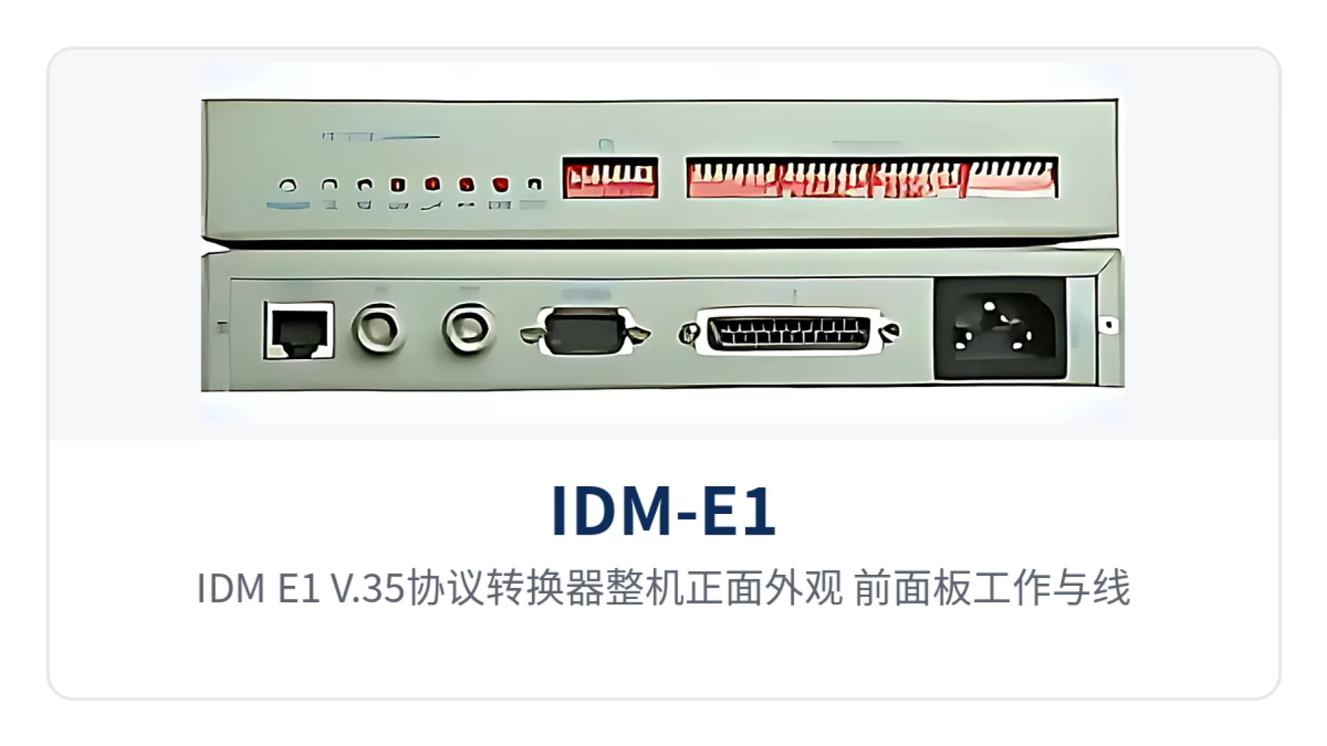
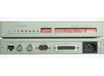
Figure 1: Overall front appearance of the IDM-E1/V.35 protocol converter, with operating and line alarm indicator LEDs on the front panel
What Kind of Device Is an E1-to-V.35 Protocol Converter?
An E1-to-V.35 protocol converter is a type of access device that restores the data carried in E1 channels to a V.35 synchronous data interface, and it often appears as an interface adaptation device in private network access and product showcases. The E1 line rate is fixed at 2048Kbps and is divided into 32 64Kbps time slots according to ITU-T Recommendation G.704; after deducting the time slots occupied by synchronization and signaling, the remaining time slots can carry user data.
The device extracts the 64K data in the designated time slots and delivers it to the DTE terminal from the DB25 interface according to the V.35 electrical and mechanical specifications, and in the reverse direction packs the terminal data back into the time slots, without any protocol parsing throughout. Upper-layer protocol messages are therefore transmitted transparently as-is, and there is no need to adjust the software configuration of the dispatch master station or service terminals during upgrades.
V.35 is a synchronous serial data interface standard in which data and clock are transmitted in a differential balanced manner, with the rate usually configured as N×64Kbps. A converter operating in DCE mode is responsible for providing transmit and receive clocks to the DTE terminal, so the terminal side no longer needs a separate clock source. The V.35 interface has long been used as the interfacing port for router WAN ports, DDN nodes, and electric power telecontrol equipment, which is precisely why E1 time slot to V.35 conversion has become one of the common interface adaptation methods in private networks.
The same E1-to-V.35 protocol converter has two usage modes, and the difference lies in how the E1 channel is allocated. IDM-E1/V.35 provides 1 group of transparent E1 channels, where the entire 2.048Mbps channel is exclusively occupied by V.35 data and the V.35 ports at both ends can be configured for 2048Kbps; IDM-FE1/V.35 provides 1 group of time-slot-divided E1 channels, where only N time slots are extracted and the remaining time slots can still be left for other services on the same E1.
What Conversions Does One Device Perform?
The conversion capability of the device centers on the mapping between E1 time slots and the V.35 data port, and the remaining functions are designed around on-site commissioning and troubleshooting. The table below lists each function item and its corresponding on-site value one by one; before configuration, you can first check against this table whether your requirements are covered, and then decide whether to choose a transparent channel or a time-slot-divided channel.
| Function | Description |
|---|---|
| E1-to-V.35 protocol conversion | Bidirectionally converts the 64K data in E1 time slots and the V.35 interface data, with bandwidth from 64Kbps to 2048Kbps, without changing the upper-layer data content |
| Transparent E1 transmission | IDM-E1/V.35 provides 1 group of transparent E1 channels, where V.35 data exclusively occupies the entire 2.048Mbps channel and the service can be enabled as long as the rates at both ends are consistent |
| Time-slot-divided transmission | IDM-FE1/V.35 provides 1 group of time-slot-divided E1 channels, where the number and positions of time slots can be set arbitrarily, and unoccupied time slots are left for other services |
| Adaptive transmit phase | Adapts to the data phase transmitted by the DTE device, so there is no need for on-site adjustment of the clock phase after replacing the terminal or the cable |
| Multiple loopback settings | Supports multiple loopback modes; together with E1 alarm indication, it helps determine segment by segment whether the failure lies on the E1 line side or the V.35 interface side |
| E1 circuit detection | Monitors the alarm and bit error status of the E1 line and outputs complete line alarm indication |
| Network management | Monitors the device operating status and sets the device operating state, so remote sites do not need to send personnel on site to change configurations |
| Dual-impedance E1 access | Provides both unbalanced 75 Ω (BNC) and balanced 120 Ω (RJ45) E1 interfaces, selected according to the on-site cable |
Key Specifications and Technical Specifications
The electrical specifications of the E1 interface and the V.35 interface determine whether a link can be enabled stably over the long term. The table below lists the parameter definitions and the applicable recommendations by interface group, and both selection and acceptance on delivery can be checked item by item. For items not listed in the table, the accompanying technical documentation and factory labels shall prevail.
| Item | Parameter/Specification | Description/Applicable Conditions |
|---|---|---|
| E1 interface line coding | HDB3 line coding | Complies with ITU-T Recommendation G.703 and provides complete line alarm indication output |
| E1 interface rate | 2048Kbps±50ppm | Interfaces with E1 channels provided by SDH, PDH, and PCM equipment |
| E1 interface impedance | Balanced port (RJ45) 120 Ω, unbalanced port (BNC) 75 Ω, adaptive | Fully complies with ITU-T Recommendations G.703 and G.704; select the port according to the cable type on site |
| E1 time slot allocation | Transparent occupation of the entire E1, or division by N 64K time slots | In time-slot-divided use, the number and positions of time slots can be set arbitrarily |
| V.35 operating mode | DCE | Provides transmit and receive clocks to the DTE terminal |
| V.35 data rate | N*64Kbps (N=1–31) | That is, 64Kbps to 2048Kbps, set according to the service bandwidth |
| V.35 interface connection | DB25 female connector (with DB25-to-M34 adapter cable) | Facilitates interfacing with the M34 interfaces of routers and nodes |
| Power supply mode | AC220V/DC-48V | AC in equipment rooms, -48V DC at communication stations |
| Overall power consumption | ≤5W | Small sites can be powered by storage batteries or solar power supply systems |
| Dimensions | 220×165×35(mm) | Desktop placement or mounted in a cabinet bracket |
| Operating temperature | -15℃~+65℃ | Covers the common temperature range of unattended equipment rooms and outdoor cabinets |
| Relative humidity | 0~95% (non-condensing) | In high-humidity environments, ensure no condensation inside the enclosure |
Three On-Site Concerns: Impedance Matching, Bandwidth Allocation, and Power Supply
The impedance form of E1 lines is not uniform on engineering sites: old stations mostly use 75 Ω coaxial cable, while new sites mostly use 120 Ω twisted pair, and impedance mismatch directly manifests as bit errors or a link that fails to come up. The device makes the two impedances adaptive on the same E1 port; 75 Ω/120 Ω adaptive means there is no need to open the unit and replace modules on site, nor to stock two models for the two types of lines—one unit on delivery is ready for work.
Bandwidth is allocated according to service requirements rather than cut uniformly at a fixed rate. The N×64K bandwidth configuration allows one E1 to take only 64K for telecontrol data and only 128K for one dispatching service, while the remaining time slots continue to carry other channels, so any step between 64K and 2M can be implemented. The difference between the transparent mode and the time-slot-divided mode is in practice whether other services are still allowed to run on this link. In electric power private network telecontrol data backhaul scenarios, this on-demand time slot allocation is particularly convenient for sharing one E1 channel with PCM equipment.
The power supply mode determines whether the device can be installed at unattended sites. AC220V/DC-48V dual power supply allows the same device to take AC in equipment rooms and -48V DC at communication stations, so there is no need to purchase separately for the two power environments; with overall power consumption ≤5W, it can also carry loads over the long term together with storage batteries or solar power supply systems, and there is no need to calculate power headroom first when expanding a site. Raytrans series bridge converters and E1-to-V.35 protocol converters can serve as the adaptation link between E1 and V.35 interfaces in government private network optical fiber communication solutions and military emergency communications vehicle solutions, working with PCM equipment and bridge converters to complete channel extension and service termination.
| Capability Label | Value on Site |
|---|---|
| 75/120 Ω adaptive | E1 line 75 Ω/120 Ω adaptive, plug-and-play on site without module replacement: BNC port for 75 Ω coaxial cable, RJ45 port for 120 Ω twisted pair |
| N×64K bandwidth | N×64Kbps flexible bandwidth, 64K to 2M private network channels allocated on demand: the number and positions of time slots are set according to service needs |
| Dual power input | AC220V/DC-48V dual power supply, suitable for equipment rooms and unattended sites: compatible with both AC and DC power environments |
| ≤5W low power consumption | Overall power consumption ≤5W; small sites can carry loads over the long term with storage batteries or solar power supply systems |
Typical Application Scenarios
The deployment of E1-to-V.35 protocol converters basically addresses sites of the kind where "an E1 transmission network already exists while the data terminals still have V.35 ports." The three industries use the device in different positions and make different trade-offs regarding impedance, bandwidth, and power supply, as described below by industry.
Electric Power Private Network: Substation Telecontrol and Metering Data Backhaul
The telecontrol equipment, electric energy metering terminals, and protection management units at substations and power supply stations mostly provide only V.35 or serial data ports, while the inter-station channels are carried by E1 provided by SDH or PDH equipment. With one E1-to-V.35 protocol converter placed at each of the station end and the dispatch end, electric power private network telecontrol data backhaul is transparently delivered over E1 time slots to the front-end processor of the dispatch master station, without protocol parsing in between, and protocol messages are transmitted transparently as-is.
Electric power sites are mostly unattended, and the equipment room temperature fluctuates with the seasons; the device's operating temperature of -15℃~+65℃ and power consumption of ≤5W fit exactly such environments. The station DC distribution panel provides -48V, which the dual power input can use directly without an additional inverter.
Rail Transit: Data Channels Between Stations and Depots
V.35 data ports are often retained between station signaling equipment, passenger information systems, and depot inspection terminals, and the channels along the line are carried by E1 provided by transmission equipment. The time-slot-divided mode is more common here: one E1 simultaneously carries several services such as signaling data, environmental monitoring, and PA control, and each service occupies only the N×64K bandwidth it needs, without interfering with one another.
Cabinet space in tunnels and elevated sections is tight, and the 220×165×35(mm) enclosure can be placed on existing trays; 75 Ω coaxial cable still exists in large quantities in old line upgrades, and the BNC port interfaces directly, eliminating the work of replacing cables and patch panels.
Military and Government Private Networks: Data Access from Equipment Rooms to Remote Nodes
In government private network optical fiber communication solutions and military emergency communications vehicle solutions, the WAN ports of core routers in private network equipment rooms are mostly V.35, and remote nodes are accessed through transmission channels. With one device at each end, the V.35 link can be established once the E1 channel is through; DDN data network access and E1-based PCM equipment network transmission access fall under the same category of use. The transparent E1 mode suits point-to-point dedicated links, while the time-slot-divided mode suits sharing one E1 with other services.
Such sites demand fast service enablement, and the equipment rooms at both ends are often attended by different organizations, leaving a limited troubleshooting window. The device supports adaptive transmit phase and multiple loopback settings; when a link fails, you can first perform a local loopback to determine the faulty segment, and then contact the line side for handling, reducing back-and-forth coordination.
How to Wire and Commission on Site?
Follow the wiring sequence of determining E1 first, then connecting V.35, and finally powering on; commissioning of one E1-to-V.35 protocol converter can be completed within five steps. The figure below shows the layout of the E1 interfaces and power terminals on the rear panel; before wiring, first check whether the cables match the interface forms, as mismatched connectors are a common cause of rework.
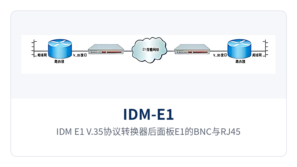
Figure 2: Close-up of the BNC and RJ45 E1 interfaces and power terminals on the rear panel of the IDM-E1/V.35 protocol converter
- Confirm the E1 interface form: use a BNC connector when 75 Ω coaxial cable is used on site, and an RJ45 connector when 120 Ω twisted pair is used. Both interfaces are provided at the same time, so simply select one according to the cable; no need to open the unit to replace a module.
- Connect the E1 line: for 75 Ω coaxial cable, make sure the core wire and the shielding layer are not shorted; for 120 Ω twisted pair, connect it in receive/transmit pairs. The E1 channel on the line side is provided by SDH, PDH, or PCM equipment.
- Connect the V.35 data cable: use a DB25 female connector with a DB25-to-M34 conversion cable to connect to the M34 interface of the DTE terminal. The interface works in DCE mode, and the clock is provided by the converter.
- Set the operating mode and bandwidth: in transparent mode, set the V.35 rate at both ends to the same value; in time slot mode, set the number and positions of time slots according to service requirements, and the time slot configuration at both ends must correspond.
- Test with loopback and alarm indication: first perform a local loopback to confirm that the V.35 side receives and transmits normally, then perform a loopback on the line side to confirm the E1 channel. After the alarm indication shows no abnormality, connect the service, and finally connect AC or -48 V DC power according to the on-site power supply conditions.
Paired configuration is a prerequisite for service activation: one end performs data encapsulation and the other end performs data restoration. The models at the two ends can differ, but the E1 channel mode and time slot arrangement must be consistent. If one end is set to transparent mode and the other to time slot mode, or the time slot positions are staggered, the link will never come up; check these two configuration items first during troubleshooting.
Selection: How to Choose Between IDM-E1/V.35 and IDM-FE1/V.35?
The only difference between the two models is whether the E1 channel is occupied as a whole or divided by time slot; the other interface specifications, power supply mode, and environmental conditions are the same. The judgment is also simple: whether other services will also run on this E1. If yes, use time slot mode; if not, use transparent mode.
| Model | E1 channel mode | V.35 channel | Application scenario |
|---|---|---|---|
| IDM-E1/V.35 | 1 group of transparent E1 channels | 1 N*64K V.35 channel | Point-to-point dedicated link, direct connection between devices at both ends, simple configuration |
| IDM-FE1/V.35 | 1 group of time-slot-divided E1 channels | 1 N*64K V.35 channel | Shared with other services on one E1, requiring designated number and positions of time slots |
Conclusion
As an E1-to-V.35 protocol converter for private network data access, the Raytrans IDM-E1/V.35 integrates conversion between E1 time slots and the V.35 interface, loopback detection, and network management functions into a 220×165×35 (mm) chassis, and its compact structure can be seen directly in the product showcase.
E1 line 75 Ω/120 Ω adaptation eliminates the need to replace modules on site, N×64K bandwidth allows channels from 64K to 2M to be allocated by service, and dual power supply AC 220 V/DC -48 V with ≤5 W power consumption suits equipment rooms and unattended sites. For electric power, rail transit, and military and government private network projects that need to connect V.35 data terminals to an existing E1 transmission network, deployment can be completed by selecting transparent or time slot mode.