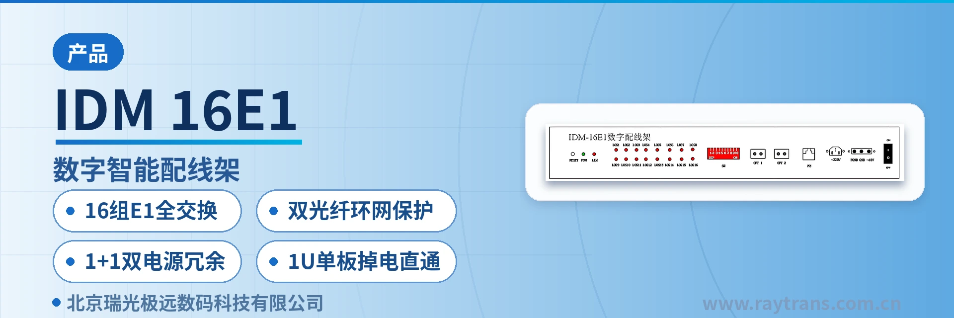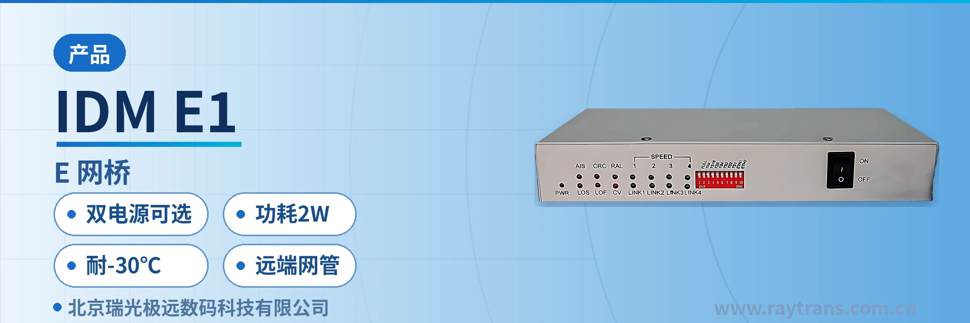
IDM GE Aggregation Bridge
63 E1 channels into 1U, single STM-1 maps 63 E1 channels, compatible with E1 from multiple manufacturers
The IDM GE/STM1 multi-channel aggregation bridge is an intelligent aggregation bridge developed by our company to meet the market demand for high-capacity Ethernet leased line access. It can aggregate 63 E1 channels into a gigabit Ethernet port and directly interface with SDH transmission equipment.
The IDM GE/STM1 multi-channel aggregation bridge is an intelligent aggregation bridge designed for high-capacity Ethernet leased line access. Developed by Beijing Ruiguang Jiyuan Digital Technology Co., Ltd., it aggregates 63 E1 channels into a gigabit Ethernet port and interfaces directly with SDH equipment. As a central-office-side 63-channel E1 aggregation bridge, this bridge converter consolidates rows of 2M interfaces and patch cords in the equipment room into a single 19-inch 1U chassis, reducing network construction and maintenance costs.
The device uses channels as the link unit to transparently carry Ethernet data. The conversion process is transparent to upper-layer services, and intercommunication is achieved when both ends are configured according to the same channel plan. For O&M, local configuration is performed through the console port, and the device can also be incorporated into unified network-wide management through the SNMP network management interface, with configuration delivery, alarms, and status queries centralized in the central equipment room. In optical transmission equipment networking scenarios, the device can be deployed together with MSTP and SDH equipment, making it suitable for application environments with high link reliability requirements, such as government private network optical fiber communication solutions and military emergency communications vehicle solutions. As a professional SDH equipment manufacturer, Raytrans provides complete selection support for SDH equipment and bridge converters in its product showcase.
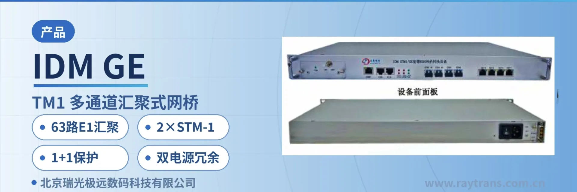
Key specifications at a glance: 63-channel E1 aggregation · 2×STM-1 interfaces · 1 optical and 1 electrical gigabit Ethernet port · 1+1 protection · dual power supply redundancy · 19-inch 1U chassis
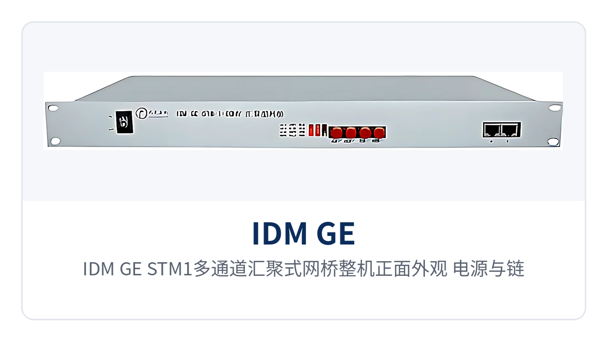
Figure 1: IDM GE/STM1 multi-channel aggregation bridge front view, power and link indicator LEDs
What kind of device is a 63-channel E1 aggregation bridge?
A 63-channel E1 aggregation bridge is a central-office aggregation device that consolidates multiple 2M-level E1 channels into a gigabit Ethernet port, functioning like a large Ethernet pipe on the equipment room side that merges scattered E1 leased lines. A single STM-1 interface can map 63 E1 channels, and the device can arbitrarily divide and configure channels 1 to 63 according to service bandwidth, with each channel consisting of one E1 or multiple (4, 8, 16) E1 channels. As a bridge converter for private network scenarios, it is often categorized in the product showcase as an SDH equipment access product and is used in direct interfacing with SDH optical transmission equipment.
Channel division allows the same chassis to simultaneously carry multiple leased lines of different sizes: a site with small bandwidth requirements is assigned one E1, while a site with concentrated services bundles multiple E1 channels into one channel. Bandwidth is automatically allocated within a channel according to the number of E1 lines, and asymmetric E1 line transmission is supported, so collection-type services with asymmetric uplink and downlink service volumes do not need to be configured according to the larger side.
The access scale of a single device depends on how many E1 channels the remote bridge uses: the more E1 interfaces at the remote end, the fewer remote stations a single device can support. The following table lists the number of connections per device by remote device type; during selection, simply convert according to the actual configuration of remote devices in the existing network.
Remote device type | Connections per device | Description/Applicable Conditions |
|---|---|---|
Single-E1 protocol converter | 63 | Each remote end occupies 1 E1 channel |
4E1 protocol converter | 15 | Each remote end occupies 4 E1 channels |
8E1 protocol converter | 7 | Each remote end occupies 8 E1 channels |
16E1 protocol converter | 3 | Each remote end occupies 16 E1 channels; the remainder is subject to the actual channel plan |
A frame sequence transmission delay difference of 64 ms is allowed between any two E1 channels within a channel, which is the basis for stable operation of the device on complex networks. Transmission latency of different E1 paths inherently differs; allowing a certain delay difference means that E1 channels do not need to be strictly equal in length and latency, and E1 circuits spanning rings and sections in carrier networks can be bundled into the same channel as usual. This feature also enables the bridge converter to adapt to existing network conditions with inconsistent E1 circuit latency across departments and regions in government private network optical fiber communication solutions.
What functions does this aggregation bridge provide? Item-by-item comparison with site requirements
Functions are concentrated in four areas: E1 aggregation, STM-1 transmission, bandwidth allocation, and O&M management, each corresponding to an action that can be verified on site. The following table lists capabilities and effects by function item, so that during selection you can compare row by row against the E1 resources, SDH port types, and O&M approach of your site.
Function | Description |
|---|---|
63-group E1 aggregation | A single device aggregates 63 groups of E1 into a gigabit Ethernet port, so the equipment room no longer needs to bring out interfaces and patch cords separately for each 2M service. |
STM-1 channel mapping | A single STM-1 interface can map 63 E1 channels, and services are transported over long distances via the existing SDH network; it can interface with both SDH equipment and MSTP platforms. |
Arbitrary channel division | Supports arbitrary division and configuration of channels 1 to 63, with each channel consisting of one E1 or multiple (4, 8, 16) E1 channels. |
Automatic bandwidth allocation | Bandwidth is automatically allocated within a channel according to the number of E1 lines; the more channels allocated, the greater the bandwidth available to that link. |
Asymmetric E1 transmission | Supports asymmetric E1 line transmission, so sites with unequal uplink and downlink service volumes can configure channels according to actual requirements. |
Dual STM-1 interfaces | Provides 2 STM-1 interfaces and can operate in SDH ring and chain networks, with the two optical ports corresponding to two transmission directions respectively. |
1+1 protection | The two STM-1 interfaces can provide 1+1 protection, so services can be maintained when one optical path fails. |
Gigabit Ethernet interface | Provides 2 gigabit Ethernet interfaces (1 optical and 1 electrical); the optical port is used for long-distance uplink, and the electrical port connects to a local switch or router. |
Multi-vendor hybrid networking | Strong compatibility; supports hybrid networking applications with single/multi-E1 bridges from different manufacturers as remote devices. |
Frame sequence delay difference tolerance | Guarantees a frame sequence transmission delay difference of 64 ms between any two E1 channels within a channel, preventing service misordering on complex networks. |
Console local configuration | Provides a console port for on-site channel division, interface parameter, and alarm configuration using a portable computer. |
SNMP unified network management | Provides an SNMP network management interface for unified network-wide management, with status and alarms of multiple devices viewed centrally. |
Dual power supply redundancy | Adopts a standard 19-inch 1U chassis and a dual power supply redundancy design, so a single power supply failure does not affect services. |
Technical specifications and interface specifications
Specifications are listed in groups by interface, channel, management, and overall unit configuration, with nominal values taken from product documentation. As an SDH bridge that interfaces directly with SDH transmission equipment, its interface forms and channel numbering must be aligned item by item with the opposite end; for items not given in the documentation, the confirmation method is noted in the Description column—confirm with the manufacturer before signing the contract rather than estimating based on similar equipment. As an SDH equipment manufacturer, Raytrans provides the interface and channel specifications below in its product showcase documentation for this type of bridge converter, which can be compared item by item with the optical transmission equipment side during selection.
Item | Parameter/Specification | Description/Applicable Conditions |
|---|---|---|
Device Model | IDM GE/STM1 multi-channel aggregation bridge | Central-office aggregation-type bridge, directly interconnected with SDH transmission equipment |
Number of STM-1 interfaces | 2 | Supports SDH ring and chain network networking and 1+1 protection |
E1 mappings per interface | 63 E1s | Upper limit of E1 mappings within a single STM-1 interface |
Channel division range | Arbitrary division from 1 to 63 channels | Each channel consists of 1 or multiple (4, 8, 16) E1s |
Bandwidth allocation within a channel | Automatically allocated according to the number of E1 lines | Supports asymmetric transmission of E1 lines |
Frame sequence delay difference tolerance | 64ms | Transmission delay difference between any two E1s within a channel |
Gigabit Ethernet interface | 1 optical + 1 electrical, 2 in total | The optical port is used for long-distance uplink; the electrical port connects to local network equipment |
Remote device compatibility | Single/multi-E1 bridges from different manufacturers | Can be mixed in one network; select the remote end according to the number of E1s |
Management interface | Console interface, SNMP network management interface | Supports unified network management across the network |
Chassis | Standard 19-inch 1U | Rack-mounted installation; sites can be installed in an integrated cabinet |
Power supply | Dual power supply redundancy | Two power feeds connected simultaneously; a single-feed failure does not affect services |
Overall power consumption | Not yet recorded in the knowledge base | Subject to the technical documentation supplied with the unit and the ordering configuration |
Operating environment (temperature, humidity) | Not yet recorded in the knowledge base | Confirm with the manufacturer according to equipment room conditions |
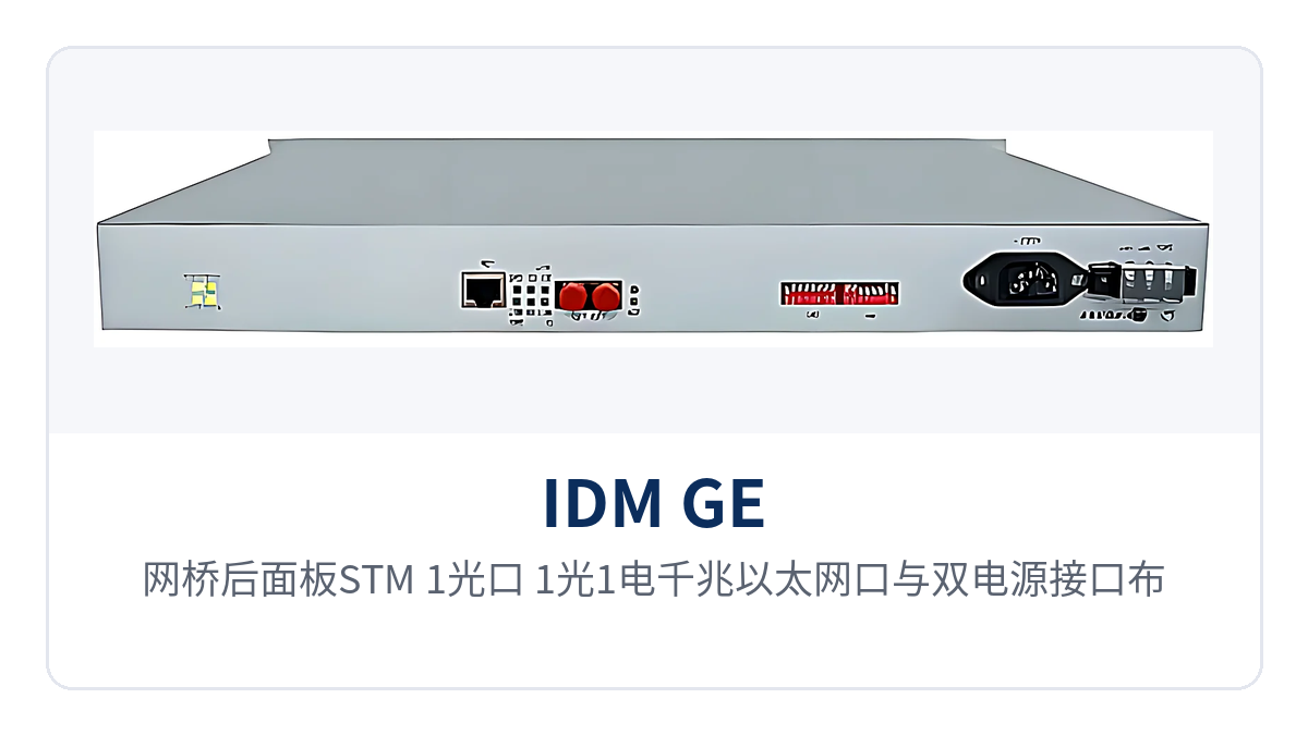
Figure 2: Layout of the STM-1 optical ports, 1 optical + 1 electrical gigabit Ethernet ports, and dual power connectors on the bridge rear panel
Four Capability Labels: 63-Channel E1 Aggregation, 2×STM-1, 1+1 Protection, Dual Power Supply Redundancy
Four phrases are commonly used on site to summarize the capabilities of this device, and the same wording can be carried through procurement lists, system diagrams, and acceptance documents. The four labels correspond to the four dimensions of capacity, transmission direction, protection, and power supply; the table below explains the boundary conditions and implementation of each.
Differentiation Point | Value on Site |
|---|---|
63-channel E1 aggregation | A single device aggregates 63 E1 groups into gigabit Ethernet ports, saving a large number of 2M interfaces and patch cords in the equipment room and reducing rack positions and points of failure at the same time. |
2×STM-1 | The two STM-1 interfaces can correspond to the two directions of a ring network and interconnect directly with SDH transmission equipment, with no intermediate device required. |
1+1 protection | Two STM-1 optical paths work simultaneously; when one fails, services are still maintained, and private network links are carried in protection mode. |
Dual power supply redundancy | The 19-inch 1U chassis accepts dual power feeds, so the device does not lose power when a single feed in the equipment room is abnormal, making it suitable for unattended sites. |
It should be noted that 1+1 protection acts on the STM-1 transmission side, while dual power supply redundancy acts on the device power supply side; the two mechanisms do not replace each other. During design, check them separately according to the reliability requirements of the site, and state both the protection mode and the power supply configuration clearly in the two lists. In a government private network optical fiber communication solution, this bridge converter is often combined with MSTP and SDH optical transmission equipment to form a ring network link; in a military emergency communications vehicle solution, its dual power supply redundancy and 1+1 protection capabilities correspond to the on-site constraints of vehicle-mounted power supply fluctuation and link interruption, and both can be checked together with the reliability requirements of these two types of scenarios during selection.
How to Network and Deploy: Point-to-Point, Chain Network, and Ring Network
The device can be networked in three ways: point-to-point, chain network, and ring network. The central side performs aggregation, and the site side hosts remote E1 bridges for access; the channel division and E1 numbering at both ends must correspond one to one. The difference among the three ways lies in the number of STM-1 optical ports used and the protection configuration, while the device itself and the configuration method remain the same.
Point-to-point: one device at each end, interconnected through an STM-1 optical direction; the gigabit Ethernet ports at both ends achieve point-to-point intercommunication, suitable for a dedicated line between two equipment rooms.
Chain network: multiple sites are connected in series along one transmission link, and the central equipment room device collects the E1 services sent by each site along the line, suitable for backbones distributed in a band shape.
Ring network: the two STM-1 interfaces connect to the two directions of the ring respectively, and the link has another transmission path; together with 1+1 protection, services are still maintained when a single optical path segment is interrupted.
Hybrid networking: remote ends can host single-E1, 4E1, 8E1, and 16E1 bridge converters from different manufacturers, and the central side aggregates them uniformly by number of E1s, so existing equipment on the network does not need to be replaced in bulk.
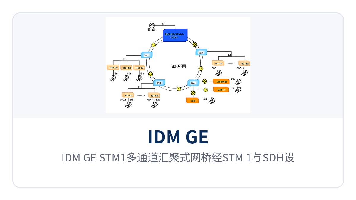
Figure 3: Topology diagram of the IDM GE/STM1 multi-channel aggregation bridge forming a ring network with SDH equipment over STM-1 and aggregating E1 services from each site
When networking, first determine the E1 circuit routing from the central equipment room to each site, then convert each service into a number of channels and write it into the channel configuration tables at both ends. In chain and ring network modes, plan the receive/transmit optical power and channel numbering of the STM-1 optical ports uniformly, and update both ends synchronously after any change at either end, avoiding the situation where one direction works and the other does not.
Typical Application Scenarios
What the following three industries have in common is that a batch of 2M channels is already running in the equipment room, and new Ethernet services need to be accessed without laying new optical cables. The role of the device in such scenarios is the same: aggregation at the central side, long-distance transmission on the SDH side, and gigabit Ethernet ports on the service side, forming a complete product showcase solution.
Electric Power Private Network: One Device in the Dispatch-Side Equipment Room Aggregates 2M Services from Multiple Sites
Substations, power supply stations, and dispatch centers usually already have a set of 2M channels carrying production services, and newly added electric energy data acquisition, records synchronization, and auxiliary control data can be transmitted remotely over these channels directly. A 63-channel E1 aggregation bridge is installed in the equipment room on the dispatch side; the E1 services sent from each site are aggregated into gigabit Ethernet (GE) ports and then uplinked to SDH equipment.
The modification work is concentrated on the rack positions and patch cords on the equipment room side: the interfaces and cables originally routed out separately for each 2M service are consolidated into one 19-inch 1U device, and cabinet space and wiring workload decrease accordingly. Dual power supply redundancy matches the operating conditions of unattended sites, and the O&M side checks device and channel status through SNMP network management.
Rail Transit: Bandwidth Allocated by E1 Channel at Stations Along the Line
Service volume varies greatly among stations along the line and section equipment rooms; some sites need only one E1 channel, while others need to bundle multiple E1 channels into one channel. The device allocates bandwidth by channel on the central side, and different stations are assigned a number of E1 channels according to actual service volume; Ethernet terminals such as cameras and environmental monitoring devices connect to existing transmission channels.
When service at a site is adjusted, only the channel configuration is changed, without touching cables: when a site is expanded, a channel originally composed of one E1 is changed to four E1 channels, and bandwidth increases accordingly. Section equipment rooms have limited space, so the 1U chassis can be installed directly in an existing integrated cabinet, and the central network management system can locate alarms on a specific channel.
Military and Government Private Networks: Eliminating Rows of 2M Patch Cords in Existing SDH Equipment Rooms
Between equipment rooms of military and government private networks, often only SDH circuits are allocated, and new Ethernet services need to be accessed without changing the existing transmission plan. The device directly interconnects with SDH transmission equipment through two STM-1 interfaces and provides one optical and one electrical gigabit Ethernet (GE) port on the service side, so the modification work is concentrated on one 1U device and two patch cords. This approach also applies to the rapid deployment requirements of government private network optical fiber communication solutions and military emergency communications vehicle solutions.
Devices at the remote end in private networks often come from different vendors, and early-installed single-E1 bridges and newly deployed 4E1 and 8E1 devices may be online at the same time. The device supports hybrid networking with single/multi-E1 bridges from different manufacturers as devices at the remote end, and the central side aggregates them uniformly by number of E1 channels, which preserves existing investment and also centralizes network-wide monitoring into one SNMP network management system.
Conclusion
As a 63-channel E1 aggregation bridge designed for central office aggregation, the IDM GE/STM1 multi-channel aggregation bridge aggregates 63 groups of E1 into gigabit Ethernet (GE) ports and directly interconnects with SDH transmission equipment through two STM-1 interfaces, reducing 2M interfaces and patch cords in the equipment room in batches. The device allocates bandwidth by channel and automatically assigns by number of E1 channels; one channel can consist of one E1 channel, or be bundled from 4, 8, or 16 E1 channels. As an SDH equipment manufacturer deeply engaged in the optical transmission equipment field, Raytrans has accumulated rich experience in the product showcase and solution implementation of MSTP and SDH equipment, and the above aggregation bridge is a representative product for central office aggregation scenarios.
For electric power, rail transit, and military and government private networks, the value of this approach lies in accessing new Ethernet services without changing the existing transmission plan: existing E1 resources continue to be used, E1 bridges from different manufacturers at the remote end continue to be used, and 1+1 protection and dual power supply redundancy place reliability on both the transmission and power supply sides. When calculating the access scale, the configuration can be derived by comparing the number of E1 channels at the remote end against the ratio table.