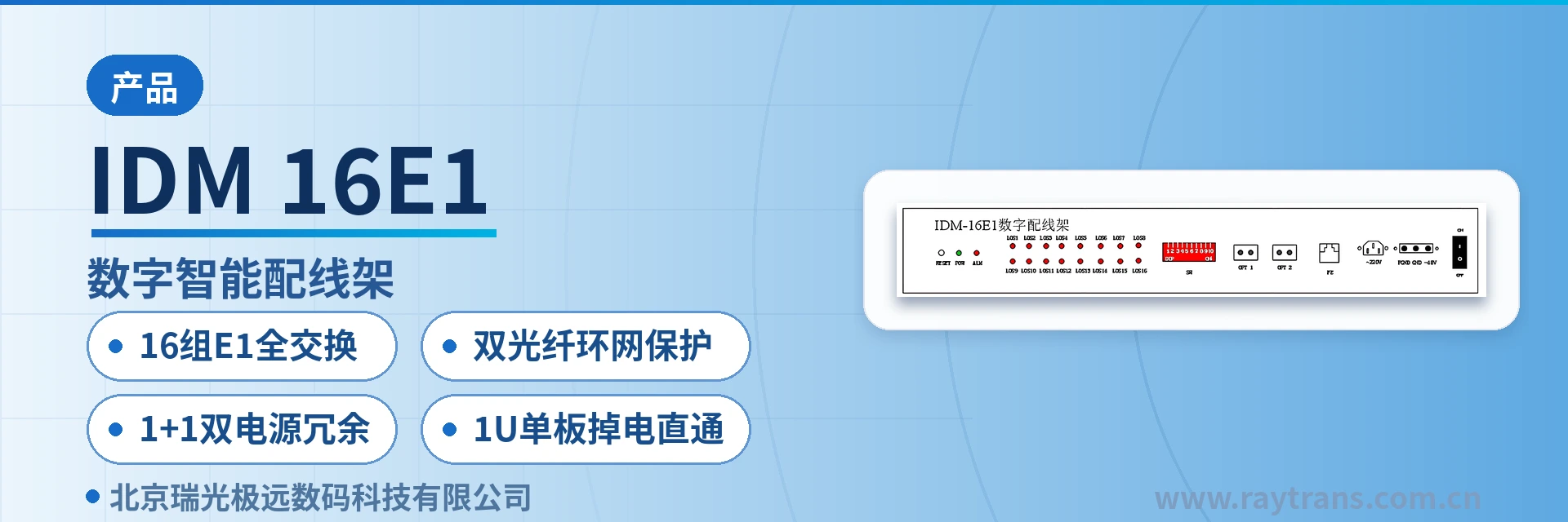
IDM-16E1 Digital Intelligent Distribution Frame
16 groups of E1 full cross-connection, dual-fiber ring network protection, power failure pass-through, services uninterrupted
The IDM-16E1 digital distribution frame is a 16-group E1 full cross-connection device providing intelligent configuration and power failure pass-through. It implements 16 groups of E1 channels with a simple board structure. The IDM-16E1 provides a network management interface, supports power failure pass-through and power failure memory, and features complete alarm monitoring, high integration, low power consumption, stable performance, and ease of use. The IDM-16E1 digital distribution frame provides complete alarm monitoring. Alarm content includes loss of E1 signal and out of frame (OOF). In addition to reporting local alarm states, it can also display the alarm state of the opposite end via the local indicator LEDs using a button.
What kind of equipment is a dual-fiber ring network protection E1 distribution frame?
The IDM-16E1 digital intelligent distribution frame is a dual-fiber ring network protection E1 distribution frame developed by Beijing Ruiguang Jiyuan Digital Technology Co., Ltd. It is used in private network equipment rooms for intelligent configuration, transparent transmission, and centralized monitoring of 16 groups of E1 (2.048 Mbit/s) channels, replacing the traditional digital distribution frame that relies on manual plugging and unplugging of coaxial patch cords. As one of the bridge converter products under Raytrans, the device performs the intelligent scheduling function for E1 channels in the private network wiring segment.
The unit adopts a single-board structure in a standard 1U chassis and can also be installed in a box form factor, reducing both rack space and cabling volume in the equipment room. Power failure pass-through and power failure memory are its fallback designs: when power is lost, E1 channels remain pass-through and services continue to be transmitted; when powered on, the configuration before the power failure is automatically restored.
Key Specifications at a Glance: 16 groups of E1 full switching · dual-fiber ring network protection · 1+1 dual power supply redundancy · 1U single-board power failure pass-through · E1 line coding HDB3 · bit rate 2.048 Mbit/s ±50 ppm · overall power consumption <15 W
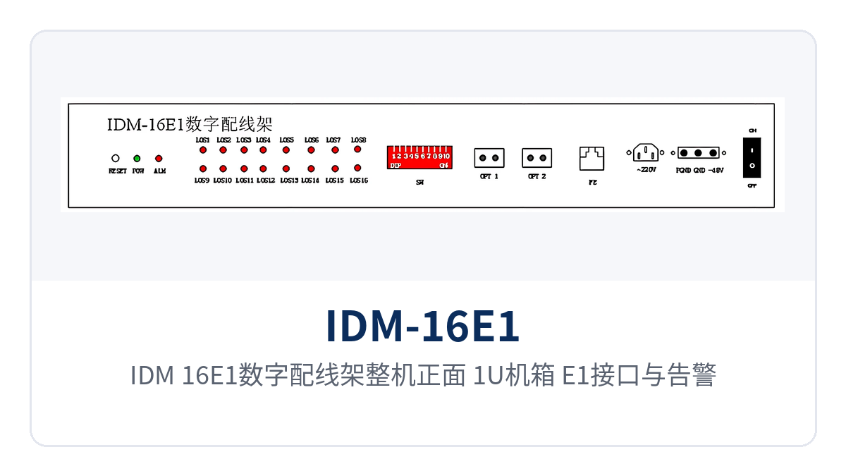
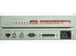
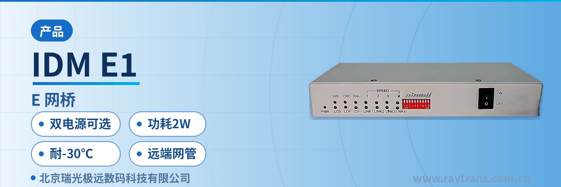
Figure 1: Front view of the IDM-16E1 digital distribution frame, 1U chassis, E1 interfaces, and alarm indicator LEDs
How does 16-group E1 full switching turn manual patch cords into software configuration?
16-group E1 full switching means equipment room rewiring no longer involves moving coaxial patch cords. The IDM-16E1 digital distribution frame uses dedicated large-scale integrated circuits to provide transparent transmission of 16 groups of E1 channels on a single board. Channel connections are established by an internal full switching matrix, making the wiring table and actual connections easier to keep consistent.
The unit's functions revolve around three main lines: E1 channel wiring, monitoring, and remote O&M. A single unit constitutes a network-manageable 16-channel E1 digital distribution device. The table below lists each capability and its corresponding description by function item, making it easy to check configurations against project requirements and to compare item by item with the working methods of existing digital distribution frames on site.
| Function | Description |
|---|---|
| 16-group E1 full switching | A single board provides 16 groups of E1 channels; channel connections are established by an internal full switching matrix, and wiring changes are completed by configuration |
| E1 transparent transmission | Dedicated large-scale integrated circuits are used; 16 groups of E1 channels are transparently transmitted at the original line coding and rate without changing the service frame structure |
| Power failure pass-through | When the device loses power, E1 channels remain connected via bypass, and 2M services continue to be transmitted |
| Power failure memory | The configuration before the power failure is automatically restored when powered on, with no need to manually re-set cross-connections |
| Alarm monitoring | Monitors line E1 signal loss and signal frame out-of-frame; alarms cover LOS, AIS, and LOF |
| Bit error monitoring | Monitors bit error events such as CRC4, FAS, and REI, and works with the network management system to assess channel quality |
| Opposite-end alarm display | In addition to reporting local-end alarms, panel buttons allow local-end indicator LEDs to display opposite-end alarm states |
| E1 tributary remote loopback | Supports E1 tributary remote loopback for segment-by-segment fault location |
| Ethernet remote management | Provides monitoring, statistics, cross-connection, loopback, offline BER test, and latency test through the network management interface |
| Optical fiber cascading and ring network protection | Supports optical fiber cascading of multiple devices; two groups of optical fibers can form ring network protection for remote cross-connection, monitoring, testing, and troubleshooting of N×16 2M channels |
| Data archiving and AI agent interfacing | Maintenance and alarm records can be archived and managed, and connected to the equipment room AI agent management system via the MCP protocol to output AI analysis reports and AI prediction reports |
How is dual-fiber ring network protection networked?
Dual-fiber ring network protection targets private network scenarios with multiple sites connected in series. Multiple IDM-16E1 digital distribution frames can be cascaded over optical fibers, connecting the distribution frames at each site end to end and using two groups of optical fibers to form a ring. If any segment of optical cable on the ring is interrupted, services can reach the opposite-end site along the other direction without reconfiguring site by site. This networking approach has practical deployment value in government private network optical fiber communication solutions and military emergency communications vehicle solutions, and Raytrans can provide corresponding networking recommendations and product showcase materials based on project site distribution.
On the ring, remote cross-connection, monitoring, testing, and troubleshooting of N×16 2M channels can be implemented. When the number of sites is N, the manageable 2M channels across the network are calculated as N×16, and the central equipment room can complete cross-site channel adjustment and status verification on a single network management system, which is the direct value of remote 2M channel cross-connection in long-line private networks.
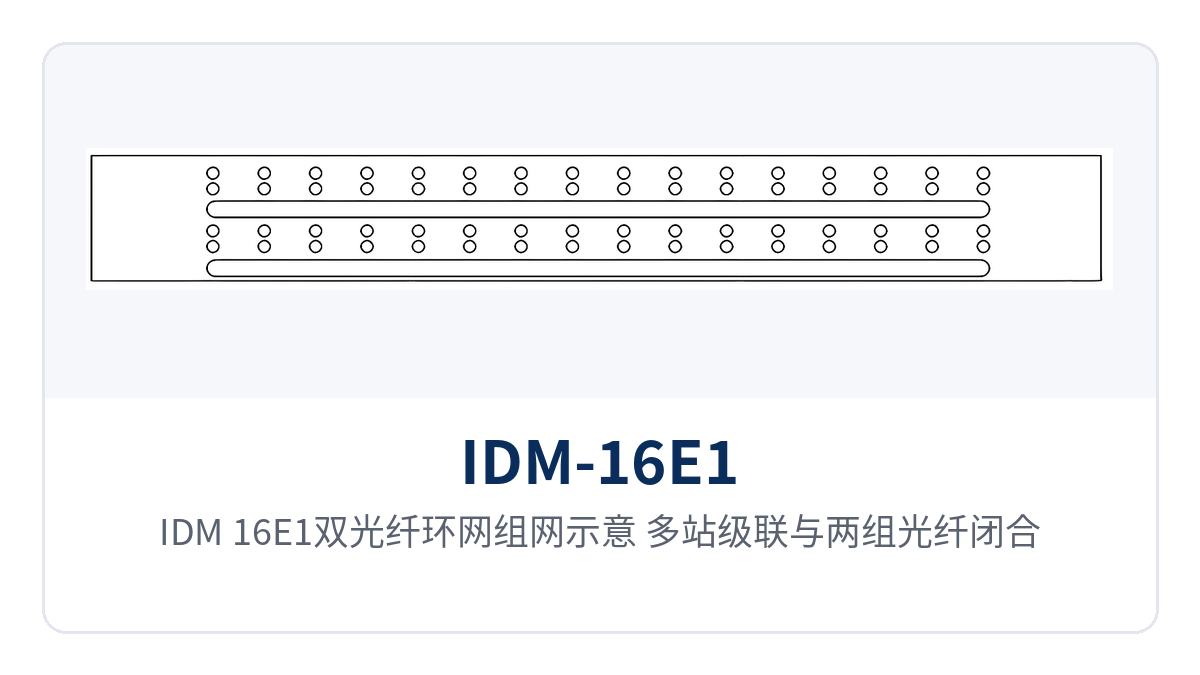
Figure 2: IDM-16E1 dual-fiber ring network networking schematic, multi-site cascading and two groups of optical fibers closed into a ring
Before networking, check the following four items item by item with the contractor to determine the optical cable route, number of directions, capacity calculation, and troubleshooting path at one time. All four items directly affect the maintenance approach after the equipment is put into operation; checking them clearly reduces rework and second site visits, and keeps network management side data consistent with on-site reality:
- Chain network: sites are connected in sequence along the line, and optical fibers are laid between adjacent sites according to the wiring table, suitable for sites distributed along a line.
- Ring network: each device connects one group of optical fibers in each of two optical directions, closed end to end to form a ring, with a single segment interruption carried by the other direction.
- Capacity calculation: a ring formed by N devices is checked for wiring capacity at N×16 2M channels, and rewiring is completed on the network management side.
- Troubleshooting path: with E1 tributary remote loopback and offline BER test, first determine whether the fault lies at the local site, the adjacent site, or the line.
How do 1+1 dual power supply redundancy and power failure pass-through keep services running?
The power supply side offers ~220 V AC and -48 V DC formats, which can also provide redundancy for each other as 1+1 protection. The AC input is designed for 220 V (165-260 V), 50 Hz, and the DC input for -48 V, 1 A. Both the existing AC mains power and DC distribution panel in the equipment room can be connected directly, with no need to add a separate power conversion unit for the device.
When two power feeds are connected at the same time, the loss of one power feed is covered by the other, and 1+1 dual power supply redundancy keeps single power supply failure outside the device. Overall power consumption is below 15 W, reducing the load on equipment room power distribution circuits and backup batteries, which particularly benefits unattended sites.
E1 distribution frame power failure pass-through means E1 channels remain physically connected when the device completely loses power. Pass-through in the IDM-16E1 digital distribution frame is achieved by bypass; when power is lost, 16 groups of E1 channels continue to transparently transmit 2M services, and power failure memory automatically restores the original configuration when powered on. Neither equipment room power outages nor maintenance power replacement will cause long interruptions to dispatch telephone and telecontrol channels.
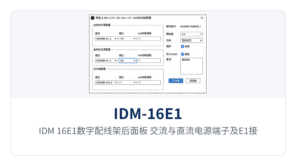
Figure 3: Rear panel of the IDM-16E1 digital distribution frame, AC and DC power supply terminals and E1 interface wiring area
The number, arrangement order, and wiring definitions of power supply terminals and E1 interfaces are subject to the manufacturer's technical documentation and the physical markings on the equipment. After wiring is completed, first check continuity channel by channel against the wiring table, then check alarm and loopback results channel by channel, and connect services only after confirming everything is correct, avoiding putting the equipment into operation with incorrect wiring.
What can alarm monitoring and network management show?
Alarm monitoring covers E1 signal loss and signal frame out-of-frame. On the network management side, alarm items such as LOS, AIS, and LOF can be viewed, and events such as CRC4, FAS, and REI can be viewed on the bit error side. Panel indicator LEDs display specific alarm states, and pressing a button allows local-end indicator LEDs to show opposite-end alarms, so on-duty personnel can determine channel continuity without logging in to the network management system.
Ethernet remote management provides monitoring, statistics, cross-connection, loopback, offline BER test, and latency test, and maintenance and alarm records can be archived and managed. After connecting to the equipment room AI agent management system via the MCP protocol, the system can output AI analysis reports and AI prediction reports, while the accompanying BI dashboard and ChatBI agent organize port status, bit error rate, and availability into directly readable conclusions.
E1 interface and unit technical specifications
E1 interfaces, power supply, and environmental parameters are the direct basis for equipment room design and incoming acceptance. The table below lists them item by item across four dimensions: interface, power supply, environment, and mechanical, with values taken from product technical documentation. Items not listed in the table are subject to the manufacturer's technical documentation and commercial confirmation, and equipment rooms with special on-site conditions are confirmed separately.
| Item | Parameter/Specification | Description/Applicable Conditions |
|---|---|---|
| E1 interface line coding | HDB3 | Standard line coding for 2.048 Mbit/s interfaces, compliant with ITU-T G.703 |
| E1 bit rate | 2.048 Mbit/s ±50 ppm | Single E1 channel rate, consistent across 16 groups of channels |
| E1 interface impedance | 75 Ω (unbalanced interface), 120 Ω (balanced interface) | Selected according to the existing E1 cabling format in the equipment room |
| Jitter and transmission characteristics | Jitter tolerance, transfer characteristics, and output jitter comply with ITU-T G.703, G.823, and G.742 | Test conditions are subject to the manufacturer's technical documentation |
| AC power supply | 220 V (165-260 V), 50 Hz | Can provide redundancy with DC as 1+1 protection |
| DC power supply | -48 V, 1 A | Can provide redundancy with AC as 1+1 protection |
| Operating temperature | 0℃~45℃ | Standard equipment room environment |
| Operating humidity | 90% (non-condensing) | Standard equipment room environment |
| Storage temperature | -20~70℃ | Transportation and storage conditions |
| Overall power consumption | <15 W | Standalone unit power consumption |
| Device specifications | 19-inch 1U / box type | Rack installation or desktop placement |
Differentiated value
The three reliability capabilities correspond to three common on-site risks: equipment room power outages and maintenance power replacement, optical cables cut by construction, and inconsistent power supply conditions across sites. Compare them item by item in the table below; the right column gives the actual results visible in the equipment room after each capability is implemented, which can be confirmed item by item with the owner during solution review:
| Customer concern | Corresponding capability of the IDM-16E1 | Result |
|---|---|---|
| 2M services must not be interrupted during equipment room power outages or maintenance power replacement | 16-group E1 full switching plus 1U single-board power failure pass-through, with configuration restored by power failure memory when powered on | Channels remain pass-through during power loss, no manual re-setup is needed after power-on, and dispatch and telecontrol services are not interrupted for long periods |
| Sites are connected in series along the line, and optical cables are easily cut by construction | Dual-fiber ring network protection; two groups of optical fibers form a ring, and any segment interruption diverts services to the other direction | A single-segment optical cable fault does not interrupt services on the entire line, and channels remain available during emergency repair |
| Sites are distributed and on-site power conditions are inconsistent | AC/DC dual power supply 1+1 redundancy, overall power consumption <15 W | Both AC mains power and -48 V DC distribution panels can be connected directly, and backup batteries can support longer runtime |
Typical application scenarios
Electric power private network dispatch equipment room
The electric power dispatch private network uses E1/2M channels to carry dispatch telephone, telecontrol, and protection information, with a large number of channels and frequent rewiring. The IDM-16E1 digital distribution frame completes intelligent configuration of 16 groups of E1 channels within a 1U chassis, and wiring changes are completed by software cross-connection on the network management side, keeping the wiring table and actual connections in the dispatch equipment room consistent. Power failure pass-through and power failure memory ensure that channels are not interrupted when power is lost in the station and that the configuration is automatically restored after power-on.
Alarm monitoring covers LOS, AIS, LOF, and CRC4, FAS, REI, so on-duty personnel can assess channel quality on the network management side. When multiple substations are connected in series, two groups of optical fibers form a ring network, so a single optical cable interruption does not affect the transmission of dispatch telephone and telecontrol data, and there is no need to reconfigure site by site during maintenance windows.
Rail transit communication
Rail transit communication equipment rooms are distributed along the line, most sites are unattended, and distribution frames remain under minimal supervision for long periods. The IDM-16E1 digital distribution frame supports optical fiber cascading of multiple devices and uses two groups of optical fibers to form ring network protection, enabling remote 2M channel cross-connection, monitoring, testing, and troubleshooting of N×16 2M channels, with E1 channel status across the entire line aggregated into a single network management system.
During section optical cable maintenance or cutover, services are transmitted along the other direction of the ring network, and train dispatch-related channels are not affected by a single point of interruption. Once maintenance and alarm records are archived, they can be connected to the equipment room AI agent management system, allowing the communications discipline to keep track of distribution status at each site without increasing the frequency of on-site inspection.
Military and government private network
The power supply conditions in the equipment rooms of military and government private networks are not uniform: some sites have only AC mains power, while others are powered by a -48V DC distribution panel. The AC and DC inputs of the IDM-16E1 digital distribution frame can serve as mutual redundancy, providing 1+1 protection. The two power sources are connected on site according to existing conditions, and both are connected at important sites. For government private network optical fiber communication solutions and military emergency communications vehicle solutions, the device can be rapidly deployed in existing 19-inch cabinets, meeting the dual requirements of private networks for channel reliability and emergency mobility.
The E1 interface uses HDB3 line coding, and its jitter tolerance, transfer characteristics, and output jitter comply with ITU-T G.703, G.823, and G.742 recommendations. Remote loopback and offline BER tests on E1 tributaries can locate the fault section without interrupting services. The 1U board structure facilitates installation in existing 19-inch cabinets, so racks do not need to be rearranged during renovation.
Figure 4: Rack installation scenario of the IDM-16E1 digital distribution frame in a 19-inch cabinet in a private network equipment room
Conclusion
The dual-fiber ring network protection E1 distribution frame packs 16 groups of full E1 cross-connect, power failure pass-through, dual-fiber ring network protection, and 1+1 dual power supply redundancy into a single 19-inch 1U device, so that 2M channels in private network equipment rooms still have a path during power outages, power supply replacement, and single-segment optical cable interruption. Raytrans has long been engaged in the private network communication field. As a representative model in its bridge converter product line, the IDM-16E1 can visually present the above differentiated capabilities in the product showcase.
For electric power dispatch private networks, rail transit communication, and military and government private networks, the IDM-16E1 digital distribution frame, with overall power consumption below 15W and network-manageable alarm monitoring, integrates distribution, protection, and remote O&M into the capabilities of a single device. During equipment room renovation, it can be directly connected according to the existing E1 format and power supply conditions.