
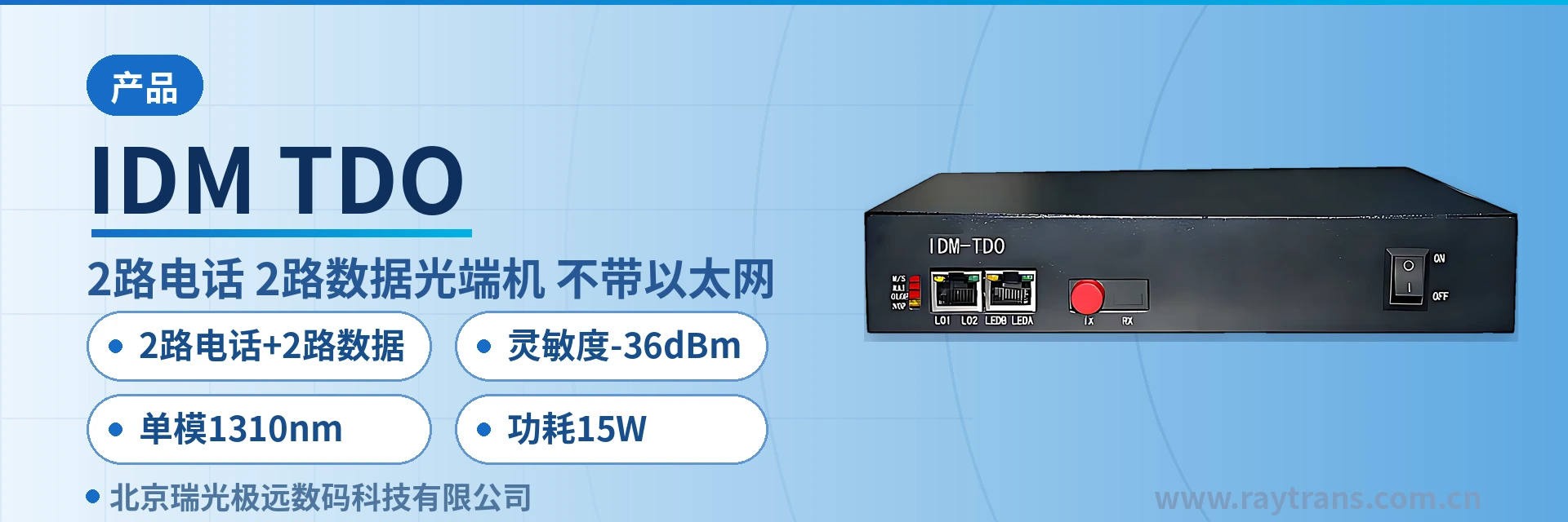
IDM-TDO Desktop Telephone Optical Multiplexer
2 voice + 2 data over the same fiber, no Ethernet port, on-site verification of interface count, saves one multi-service device
The IDM-TDO desktop multi-service optical multiplexer mainly provides 2 telephone interfaces. The IDM-TDO desktop multi-service optical multiplexer extends voice services to various user areas, replacing remote small offices, enabling cross-boundary line extension, and alleviating the switching office; or within urban areas, it overcomes the bandwidth and transmission distance limitations of twisted pair, thereby expanding the service coverage of the switching office.
The IDM-TDO desktop 2-channel telephone and 2-channel data optical multiplexer is a desktop optical multiplexer that multiplexes 2 telephone channels and 2 data channels onto a single fiber for point-to-point transmission. Developed by Beijing Ruiguang Jiyuan Digital Technology Co., Ltd. (Raytrans), it is used for voice and low-speed data access between a switching office and remote stations, and is a typical optical multiplexer product for access layer applications.
The device extends voice services to each subscriber area, can replace remote small offices and implement cross-boundary line extension, relieving the line provisioning pressure on the switching office; within urban areas it avoids the bandwidth and transmission distance constraints of twisted pair, expanding the service range of the switching office. At the remote station only one fiber needs to be laid, and services are restored once telephones and data terminals are in place. As a professional optical multiplexer manufacturer, Raytrans can showcase multi-service access capabilities around such products, providing multi-service optical multiplexer and telephone optical multiplexer selection support for scenarios such as government private network optical fiber communication solutions.
Key Specifications at a Glance: 2-channel telephone + 2-channel data · single-mode 1310 nm · sensitivity -36 dBm · power consumption 15 W · FC optical port (SC and others can be customized) · DC5 or AC 220 V dual power supply · desktop enclosure
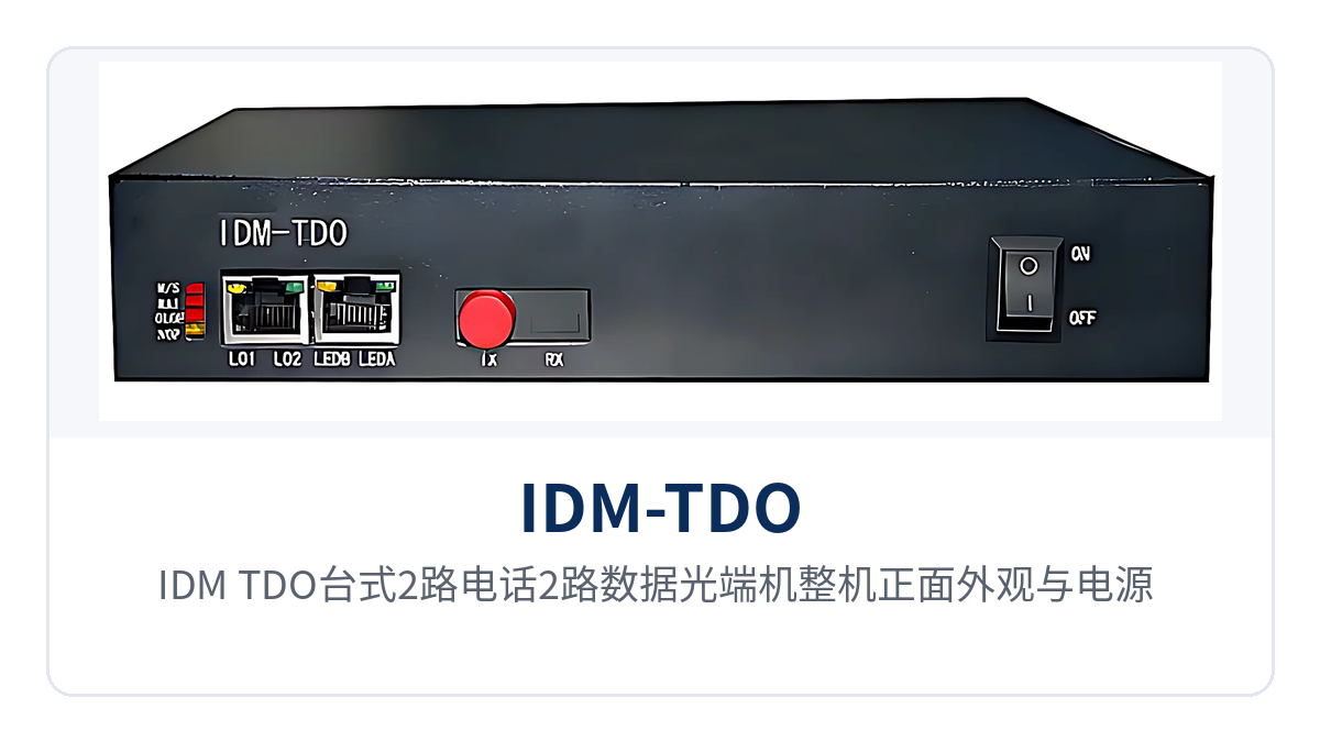
Figure 1: Close-up of the front panel, power and optical link indicator LEDs of the IDM-TDO desktop 2-channel telephone and 2-channel data optical multiplexer
What Is the Desktop 2-Channel Telephone and 2-Channel Data Optical Multiplexer
The desktop 2-channel telephone and 2-channel data optical multiplexer is a point-to-point fiber access device used in pairs at both ends, with one end connected on the switching office side and the other placed in a remote equipment room or subscriber area. The two devices are connected by a single-mode fiber, and voice and data are transmitted bidirectionally over the optical path. As a compact product showcase, the device performs transparent transmission of voice and low-speed data between the wiring closet and remote stations.
The IDM-TDO uses a desktop-type enclosure structure with high integration and a small footprint, and can be placed directly on a workbench in the wiring closet or on a tray in a small cabinet without occupying a 19-inch rack position. The device provides 1 optical channel and supports both dual-fiber and single-fiber configurations, operates at single-mode 1310 nm, and uses FC optical interfaces by default, with SC and others customizable according to the on-site optical cable termination method. Among similar optical multiplexer products, this telephone optical multiplexer stands out for its simple interfaces and small on-site verification effort.
The transmit optical power is -2 to -11 dBm and the receiver sensitivity is better than -36 dBm; the difference between the two is the optical power budget available for this link. On links with relatively high optical cable loss, more splice points, or aged connector end faces, the received optical power still falls above the sensitivity threshold after degradation, and voice and data can continue to be transmitted.
What Services Can One IDM-TDO Carry
The service interfaces of the IDM-TDO are configured in two categories, voice and data: the 2 telephone channels handle access of remote telephones or exchange equipment, and the 2 data channels handle low-speed data channels, with all services sharing a single fiber. The functions and corresponding interfaces are listed in the table below for item-by-item verification against the site list; the specific configuration is subject to the ordering list and the manufacturer's technical documentation.
| Function | Description |
|---|---|
| 2-channel telephone access | Provides 2 ordinary telephone interfaces with caller ID (CID) support; FXO/FXS interfaces are configured according to the interconnection direction and can connect to telephones or exchange equipment |
| 2-channel data access | The device is also equipped with 2 data channels, carried independently of the voice channels, so low-speed data does not contend with call handling for the same channel |
| Voice and data multiplexing over one fiber | 2 telephone channels and 2 data channels are multiplexed onto a single fiber, so remote stations do not need to lay separate cables for the two service types |
| Single optical channel | 1 optical channel, supporting dual-fiber and single-fiber configurations, operating at single-mode 1310 nm, FC interface, with SC and others customizable |
| Alarm indication | The panel provides power, optical link, and service status indications, so on-site personnel can identify the fault section by indicator position when the link is abnormal |
| Desktop enclosure structure | Desktop-type enclosure with high integration and a small footprint, suitable for placement on a wiring closet desktop, in a wall-mounted box, or in a small cabinet |
| Cross-boundary line extension | Replaces remote small offices and deferred switching offices, expanding the service range of the switching office, so remote line provisioning does not require a new equipment room |
| No Ethernet port | The device is designed only for voice and low-speed data access, with simple interface relationships, small on-site verification effort, and low risk of misconnection |
The data channels and voice channels are independent of each other, which is the main difference between this device and ordinary telephone optical multiplexers that carry voice only. When a remote station needs both calls and backhaul of meter or status data, voice and data arrive over the same fiber, so there is no need to lay an additional pair of cables for data or add another multi-service optical multiplexer.
Key Specifications: How to Verify Optical Interfaces, Telephones, and the Power Supply and Environment
The specifications are listed in five groups: optical interfaces, telephone interfaces, data channels, power supply and power consumption, and environmental conditions. The devices at both ends are used in pairs, and the rate, wavelength, and interface type of the optical interfaces must match. During verification, first check whether the optical link budget covers the actual route, then check the number of voice channels and the interface direction, and finally confirm the power supply mode and installation environment.
Optical Interface Parameters
| Item | Parameter/Specification | Description/Applicable Conditions |
|---|---|---|
| Interface type | FC (SC and others can be customized) | Selected according to the on-site optical cable termination method; specify at ordering |
| Fiber mode | Single-mode (multi-mode optional) | Single-mode is the standard configuration; multi-mode is confirmed per project |
| Optical channel | 1 channel, supporting dual-fiber and single-fiber configurations | Used in pairs at both ends, with receive/transmit directions connected correspondingly |
| Optical fiber rate | 155 bps ±50 ppm | As stated in the original product documentation; the rate and optical module configuration are subject to the manufacturer's technical documentation |
| Wavelength | 1310 nm | The wavelength and interface type must be consistent at both ends |
| Transmit optical power | -2 to -11 dBm | Available optical power range on the transmit side |
| Receiver sensitivity | Better than -36 dBm | Lower limit of available optical power on the receive side |
For optical interfaces, first match the interface type: FC is the default; when the optical cable termination is SC or another type, specify it at ordering to avoid adding a fiber adapter on site due to connector mismatch. Single-mode 1310 nm is the standard configuration, and multi-mode is confirmed per project; the devices at both ends can be enabled only when their wavelength and interface type are consistent.
Telephone Interface Parameters
| Item | Parameter/Specification | Description/Applicable Conditions |
|---|---|---|
| Number of telephone channels | 2 | Provides caller ID (CID); can connect to telephones or exchange equipment |
| Interface type | FXO/FXS | Configured according to the on-site interconnection direction, corresponding to the exchange side and the telephone side respectively |
| Audio range | 300 Hz to 3400 Hz | Telephone voice bandwidth, covering the voice frequency band |
| Impedance | Three-element complex impedance 200 Ω + 560 Ω//0.1 μF | Matches the SPC exchange and ordinary telephone side |
| Compression | ITU G.711 A-law | Common encoding for domestic telephone networks, interoperable with mainstream exchange equipment |
| Loop current | 25 mA/channel | Ensures normal power feed to telephones |
Voice channel intercommunication depends on two items, encoding and impedance: ITU G.711 A-law is the common encoding for domestic telephone networks, the three-element complex impedance 200 Ω + 560 Ω//0.1 μF matches the SPC exchange and ordinary telephone side, and the loop current of 25 mA/channel ensures normal power feed to telephones. On site, calls can be made by connecting a telephone directly to the telephone port, without additional power feed equipment.
Data Channel and Power Supply and Environment Parameters
| Item | Parameter/Specification | Description/Applicable Conditions |
|---|---|---|
| Number of data channels | 2 | Carried independently of the voice channels; the interface type is confirmed per the ordering configuration |
| Power supply mode | DC5 or AC 220 V | AC is taken in wiring closets with mains power, and DC at DC sites; selected at ordering |
| Overall power consumption | 15 W | Low power draw and heat dissipation pressure for long-term online operation |
| Operating temperature | 0 ℃ to +50 ℃ | For equipment rooms, wiring closets, and well-ventilated equipment boxes |
| Relative humidity | 95% non-condensing | The applicable condition in high-humidity environments is non-condensing |
| Enclosure form | Desktop (desktop type) | High integration and small footprint; can be placed on a desktop or a tray in a small cabinet |
The interface type of the 2 data channels is confirmed per the ordering configuration, and the corresponding configuration is selected on site according to the interface standard of the opposite end. The data channels and voice channels each occupy an independent channel over the optical path, so an abnormality in one service type does not affect transmission of the other, and the remote end only needs to connect cables separately by service port.
The power supply mode can be selected between DC5 and AC 220 V: where mains power is available in the equipment room and wiring closet, AC is used; where only DC power is available on site, the DC configuration is used, and no additional inverter or rectifier module is needed inside the device. With an overall power consumption of 15 W, the power draw and heat dissipation pressure for long-term online operation are both low.
Differentiated Value: Independent Carrying, -36 dBm Sensitivity, and 15 W Power Consumption
The differentiated value of the IDM-TDO centers on three items: service composition, receiver sensitivity, and power supply and power consumption. Each item corresponds to verifiable specifications that can be copied directly into technical specifications and bid parameter tables. All three capabilities hold simultaneously at remote stations and unattended equipment rooms.
| Differentiation Point | Corresponding Capability and Specifications | Applicable Conditions and Value |
|---|---|---|
| 2 telephone channels + 2 data channels carried independently, with voice and data extended over one fiber to remote stations | 2 telephone channels and 2 data channels each occupy an independent channel and share a single fiber | Remote stations do not need to lay separate cables for voice and data; both service types can be enabled once one fiber is in place |
| Receiver sensitivity better than -36 dBm, with stable calls on weak-light long-distance links | Transmit optical power -2 to -11 dBm, receiver sensitivity better than -36 dBm, single-mode 1310 nm | Links with relatively high optical cable loss and more splice points still have optical power margin, and calls can continue to be transmitted |
| DC5 or AC 220 V dual power supply options, with overall power consumption of only 15 W for unattended operation | DC5 or AC 220 V dual power supply, overall power consumption 15 W | Both DC sites and wiring closets with mains power can draw power directly, so unattended equipment rooms do not need separate modification for power supply and heat dissipation |
| High integration of the desktop enclosure | Desktop-type structure with high integration and a small footprint | Can be placed on a wiring closet desktop, in a wall-mounted box, or in a small cabinet without occupying a rack position |
In government private network optical fiber communication solutions, such devices can handle voice and low-speed data access at remote stations. As an optical multiplexer manufacturer, Raytrans provides technical support from selection to ordering configuration, making it easy for projects to verify cross-boundary line extension requirements and interface configurations item by item against the site list.
How to Calculate Weak-Light Long-Distance Links
Whether an optical link can be enabled is calculated from the margin between the transmit optical power and the receiver sensitivity: the IDM-TDO has a transmit optical power of -2 to -11 dBm and a receiver sensitivity better than -36 dBm. Calculated at the lower transmit limit of -11 dBm, the available link loss is about 25 dB; calculated at -2 dBm, it is about 34 dB. The actual margin must also deduct the loss per kilometer of optical cable and the loss of each splice point and fiber adapter, and in engineering practice about 3 dB is reserved at each end as spare margin.
The calculation sequence is to first measure the actual route length, then accumulate the loss per kilometer and the number of splice points and fiber adapters, and finally compare with the available budget of 25 to 34 dB. If the budget is insufficient, first clean the optical fiber end faces at both ends and reduce adapter connections; if still insufficient, consider replacing the optical module or using segmented repeaters. It is not recommended to use up the distance according to theoretical values. As a professional optical multiplexer manufacturer, Raytrans has accumulated extensive experience in calculating weak-light long-distance links in government private network optical fiber communication solutions, and every optical multiplexer in its product showcase is verified against the link budget using this method.
Typical Application Scenarios
Electric Power Distribution Network Communication: Voice and Data Backhaul over One Fiber at Substations and Switching Stations
Substations, switching stations, and power supply stations of the electric power distribution network are distributed across urban and suburban areas, with distances between stations ranging from a few kilometers to tens of kilometers, and most equipment rooms have no permanent on-duty personnel. The IDM-TDO uses one fiber to deliver 2 dispatch telephone channels and 2 data channels to the remote end, so dispatch calls and in-station meter and status data are backhauled over the same link, without laying separate cables for the two service types.
Power supply access conditions at electric power sites are not uniform: wiring closets in urban areas mostly have AC mains power, while suburban sites may have only DC power. The device supports both DC5 and AC 220 V power supply modes with an overall power consumption of 15 W, so sites can draw power according to existing power supply conditions without adding a separate power distribution panel or fan for this device.
Military and Public Security Private Networks: Independent Voice Channels Between Duty Posts and Command Posts
Duty posts, checkpoints, and temporary command posts of the military and public security are often far from switching offices, and public network telephony is generally not suitable as the sole means of communication. IDM-TDO extends 2 telephone lines to the duty post, with the entire call carried over a dedicated optical fiber channel that is physically isolated from the public network; the 2 data channels are used for status backhaul from service terminals, with voice and data each using their own channel and not contending with each other. Such scenarios are exactly one of the typical applications of the Raytrans government private network optical fiber communication solution.
Equipment room conditions at field duty posts are simple, the device is small, and the wiring relationships are clear; once the optical fiber patch cords and telephone cables are connected according to the labels, the service can be enabled. When a link is abnormal, first check the panel alarm indication, then measure the received optical power with an optical power meter and compare it against the receiver sensitivity specification of better than -36 dBm to determine whether the cause is equipment failure or excessive optical cable loss.
Communications Along Rail Transit Lines: Section Telephones and Trackside Data Extended Together
Station duty rooms, traction substations, and equipment rooms along rail transit lines are distributed on both sides of the line, with spacing between stations ranging from a few hundred meters to more than ten kilometers, and equipment room space is tight. IDM-TDO uses a desktop enclosure installed in a small cabinet or wall-mounted box in the equipment room; a single fiber delivers 2 section telephone channels and 2 trackside data channels to the nearby station, so calls between duty operators and dispatchers do not depend on wireless coverage.
Cabinets along the line are mostly unattended, with high temperatures inside the box in summer and low temperatures in winter. The device is installed in a well-ventilated cabinet under operating temperature conditions of 0℃ to +50℃ and 95% non-condensing humidity, avoiding direct sunlight and condensation accumulation. During inspection, confirm item by item in three steps: the received optical power at the optical port, off-hook listening tests on the voice channels, and data channel backhaul.
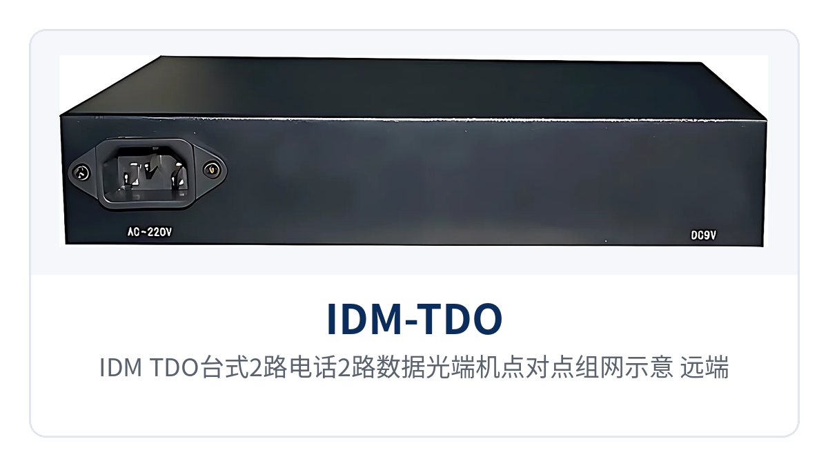
Figure 2: Point-to-point networking schematic of the IDM-TDO desktop 2-channel telephone 2-channel data optical multiplexer; remote telephones and data terminals access the switching office over a single-mode fiber
How to Deploy On-Site Wiring and Service Activation
Wiring corresponds item by item by service type: telephones use telephone cables, data uses data cables, and the optical path uses optical fiber patch cords, with devices at both ends in a paired configuration and service ports matched one to one. Before installation, verify the number and direction of interfaces at both ends, then enable the services item by item in the order below, so that if all services are enabled at once you will not be unable to tell which segment a point of failure lies in.
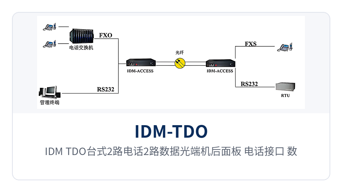
Figure 3: Close-up of the rear panel layout of the IDM-TDO desktop 2-channel telephone 2-channel data optical multiplexer, showing the telephone interfaces, data interfaces, and FC optical ports
| Service | Equipment-side interface | On-site connection | Description |
|---|---|---|---|
| Telephone | Telephone interface (FXO/FXS configured by direction) | Telephone, switching equipment | Audio range 300 Hz to 3400 Hz, A-law per ITU G.711, loop current 25 mA per channel |
| Data | Data interface (configured per order) | Data terminal, acquisition device | Carried independently of the voice channel; interface type confirmed against the opposite-end equipment |
| Optical path | FC (SC and others can be customized) | Optical fiber patch cord, optical cable | Single-mode 1310 nm; wavelength and interface type paired at both ends |
| Power | DC5 or AC 220 V | Mains power or direct current power supply | Select one of the two according to on-site power supply conditions |
- Power-on self-test: connect DC5 or AC 220 V power, confirm the panel power indication is normal, the overall power consumption is about 15 W, and there is no obvious temperature rise in the chassis.
- Optical path verification: after cleaning the optical fiber end faces, connect the patch cords, and measure the received optical power with an optical power meter to confirm it is above the receiver sensitivity threshold of better than -36 dBm.
- Telephone activation: connect telephones or switching equipment, go off-hook and listen on each channel, and confirm that ringing, conversation, and hang-up release work normally.
- Data activation: connect data terminals and confirm that the 2 data channels receive and transmit normally in both directions and do not affect each other when working at the same time as voice traffic.
- Record and archive: register the device numbers at both ends, the received optical power at the optical ports, and the service port correspondence as a comparison basis for subsequent inspection.
How to Select a 2-Channel Telephone 2-Channel Data Optical Multiplexer
Selection proceeds through five items: service list, optical interface, link budget, power supply mode, and installation position. IDM-TDO is a 2-channel telephone optical multiplexer, with interfaces configured for voice and low-speed data; all five items correspond to conditions that can be verified on site, so the configuration can be finalized by confirming them one by one during the design stage, without having to change interface direction and power supply type after ordering. As an optical multiplexer manufacturer, Raytrans clearly marks each selection condition for this model in its product showcase, making it easy for designers to compare them one by one.
- Service list: confirm that the remote end only needs voice and low-speed data; if networking is also required on site, choose another model with Ethernet ports, as this model does not have Ethernet ports.
- Optical interface: confirm the optical cable termination method (FC or SC, etc.) and fiber mode; single-mode is the standard configuration, and multi-mode is confirmed per project.
- Link budget: calculate according to the actual route length and the number of splice points and fiber adapters; the available budget can be estimated at 25 to 34 dB, and if insufficient, first optimize the end faces and adapters.
- Power supply mode: if mains power is available in the wiring closet, use AC 220 V; if only a direct current power supply is available on site, use DC5; the two modes are selected at the time of ordering.
- Installation position: the desktop enclosure is suitable for desktops, wall-mounted boxes, and small cabinet trays; confirm the placement position and heat dissipation clearance according to on-site space.
Conclusion
The IDM-TDO desktop 2-channel telephone 2-channel data optical multiplexer multiplexes 2 telephone channels and 2 data channels onto a single-mode fiber, with receiver sensitivity better than -36 dBm, dual DC5 or AC 220 V power supply, and overall power consumption of 15 W, making it suitable for remote access in electric power distribution networks, military and police private networks, and along rail transit lines.
A remote station needs only a single fiber and one desktop device to extend voice and data simultaneously to the user area, replacing remote small offices to complete cross-boundary line extension. During selection, verify the five items of service list, optical interface, link budget, power supply, and installation position, then write the interface direction at both ends and the optical port type into the ordering list, and both activation and later maintenance will be easier.


