

IDM OMP2400-30E Ultra-Broadband Integrated Service Optical Multiplexing Equipment
2.5G optical port 1+1
Provides 2 × 2.5G optical ports, 30-channel telephone service interfaces (FXO, FXS, or magneto optional), 4 groups of physically isolated wire-speed 100M Ethernet (400M in total), two groups of physically isolated wire-speed 1000M Ethernet (2000M in total), E1 (1–4 E1 channels in total), HDMI high-definition video transmission, and other subscriber interfaces.
The 6-channel isolated Ethernet telephone optical multiplexer is an ultra-broadband integrated service optical multiplexing equipment developed by Beijing Ruiguang Jiyuan Digital Technology Co., Ltd. under model IDM OMP2400-30E. As an optical multiplexer product designed for multi-scenario applications, the IDM OMP2400-30E transmits 30 telephone channels, 4 groups of E1 leased lines, 6 physically isolated Ethernet interfaces and HDMI high-definition video simultaneously over a pair of 2.5Gbps optical fibers, making it suitable for multi-service-over-one-fiber backhaul in electric power and energy, rail transit, and military and government private networks. The unit adopts the PCM30/31 format, multiplexing voice, E1, data and video onto the same pair of optical fibers over their respective channels, so the equipment room does not need to deploy a separate device for each service, fully demonstrating the integration advantages of a multi-service optical multiplexer.
The IDM OMP2400-30E provides two 2.5Gbps SFP optical ports and supports 1+1 protection for optical ports. With one unit deployed at each end and connected over a pair of optical fibers, telephone, E1 and Ethernet services intercommunicate as-is. The standard 19-inch 1U chassis architecture facilitates rack installation, and together with comprehensive function control switches and alarm indications, the operating status of the site can be checked at a glance; 30 telephone channels, 4 groups of E1 transparent transmission and 6 isolated Ethernet interfaces are all completed within the same 1U device, replacing the previous deployment approach of stacking multiple single-function devices. As a professional converged platform of a telephone optical multiplexer and a video optical multiplexer, the device flexibly adapts to various application scenarios such as a government private network optical fiber communication solution, a military emergency communications vehicle solution and a smart mining communication solution, demonstrating the technical strength and product showcase capabilities of Raytrans among optical multiplexer manufacturers.
Key specifications at a glance: 2.5G optical port 1+1 (2×2.5Gbps SFP) · Telephone 30 channels (FXO/FXS/magneto optional) · E1 1-4 channels transparent transmission · Ethernet 6 physically isolated (2×1000M+4×100M, 2400M in total) · HDMI high-definition video · DC-48V/AC220V dual power supply · Overall power consumption ≤100W · 19-inch 1U chassis
What kind of device is a 6-channel isolated Ethernet telephone optical multiplexer
The 6-channel isolated Ethernet telephone optical multiplexer is a multi-service optical multiplexer that multiplexes telephone voice, E1 leased lines, Ethernet data and high-definition video onto the same pair of optical fibers for transmission, and the IDM OMP2400-30E is one of its product showcases featuring 2.5G bandwidth, dual optical port mutual backup and 6 physically isolated Ethernet interfaces. On a single 2.5G optical link, the device provides 2 groups of wire-speed 1000M and 4 groups of wire-speed 100M Ethernet ports; the 6 groups of ports are independent of one another, services do not interfere with one another, and 30 telephone channels and 4 groups of E1 leased lines are carried at the same time. Once all services share a pair of optical fibers, cross-site cabling involves only optical cable work, and civil construction and wiring costs decrease accordingly. As a representative model of the professional optical multiplexer manufacturer Raytrans, this telephone optical multiplexer has mature applications in government private network optical fiber communication solutions, military emergency communications vehicle solutions and smart mining communication solutions.
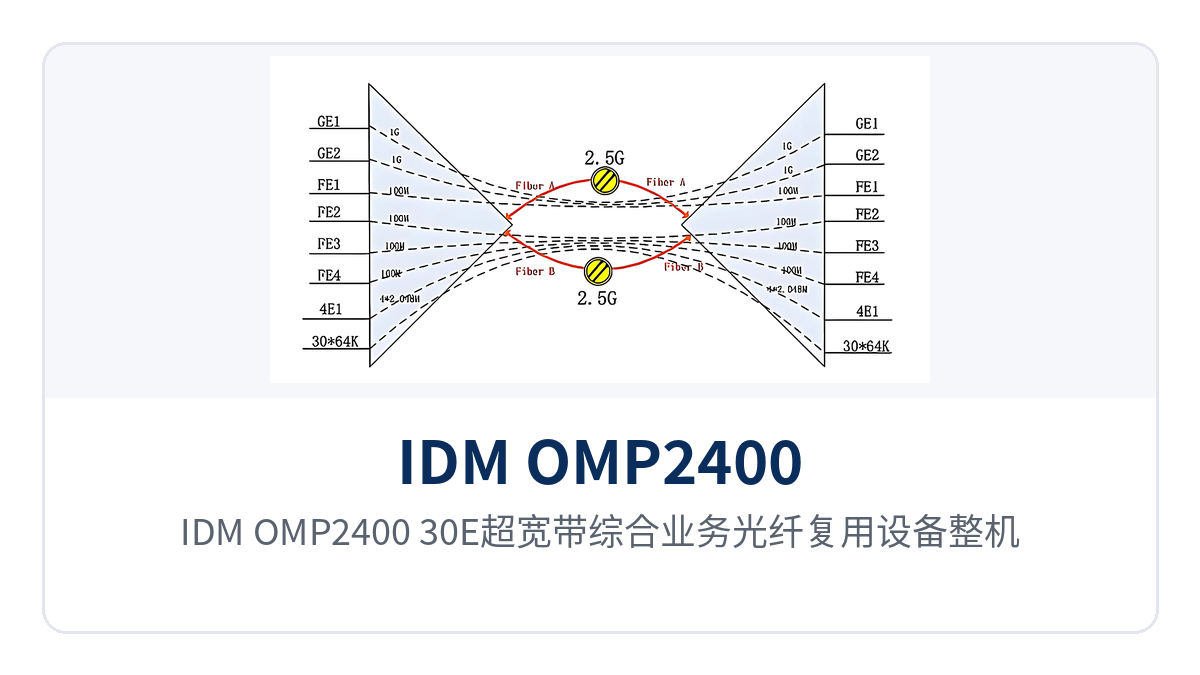
Figure 1: Overall appearance of the IDM OMP2400-30E ultra-broadband integrated service optical multiplexing equipment
One device carries 30 telephone channels, 4 groups of E1 transparent transmission and HDMI video simultaneously
The IDM OMP2400-30E concentrates the subscriber interfaces originally scattered across multiple devices into a single 1U chassis, where 30 telephone channels, 4 groups of E1 transparent transmission, HDMI high-definition video and 6 physically isolated Ethernet interfaces can operate online simultaneously. The types, capacities and applicable conditions of the service interfaces are shown in the table below; the specific board configuration is subject to the ordering model:
Function | Description |
|---|---|
30-channel telephone access | FXO, FXS or magneto interfaces optional, audio range 300Hz~3400Hz, A-law companding per ITU G.711, loop current 25mA per channel, directly connected to SPC exchanges, analog trunks or magneto telephones |
4 groups of E1 transparent transmission | Provides 1-4 E1 channels, bit rate 2048Kbps, line coding HDB3, compliant with ITU-T G.703, frame structure PCM30/31, transparent transmission mode does not change the time slot content, and existing E1 devices at the opposite end require no configuration changes |
Voice and E1 multiplexing and transmission | 30 telephone channels and 4 groups of E1 transparent transmission are multiplexed into the 2.5G optical link over their respective channels and reach the opposite end simultaneously over a pair of optical fibers, with the two service types not occupying each other's bandwidth |
6 physically isolated Ethernet interfaces | 2 groups of wire-speed 1000M (2000M in total) plus 4 groups of wire-speed 100M (400M in total), totaling 2400M of physically isolated Ethernet, with independent bandwidth per port and security zoning |
HDMI high-definition video | Supports HDMI high-definition video transmission, reaching the opposite end over the same pair of 2.5G optical fibers as telephone and E1 services |
2.5G optical port 1+1 protection | Two 2.5Gbps SFP optical ports are configured as primary and backup; if either optical port suffers a fiber break, services switch over automatically, with dual-fiber mutual backup |
SNMP network management and alarms | Provides a standard SNMP network management interface; together with function control switches and alarm indications, the operating status of the site can be monitored remotely |
Telephone interfaces are encoded with A-law companding per ITU G.711 with a loop current of 25mA per channel, and no additional conversion equipment is required when connecting to SPC exchanges, analog trunks and magneto telephones; E1 interfaces comply with ITU-T G.703, with line coding HDB3 and selectable 75Ω/120Ω impedance, and in transparent transmission mode the time slot content is not changed, so the data configuration of dispatch automation equipment at the opposite end can be retained as-is. HDMI high-definition video shares the same pair of 2.5G optical fibers with telephone and E1 services, so surveillance video and dispatch voice can be backhauled to the central equipment room together, with no need to lay separate cables for video. This multi-service optical multiplexer integrates the functions of a video optical multiplexer and a telephone optical multiplexer on the same platform, so a single device completes access for multiple services.
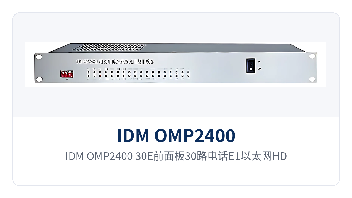
Figure 2: Front panel layout of the IDM OMP2400-30E with 30 telephone, E1, Ethernet and HDMI interfaces
How does 2.5G optical port 1+1 protection keep services uninterrupted during a fiber break
2.5G optical port 1+1 protection configures the two 2.5Gbps SFP optical ports on the device as two optical fiber channels, one primary and one backup; services are normally transmitted over the primary optical fiber while the backup optical fiber remains in hot standby. When the primary optical port suffers a fiber break, optical module degradation or an abnormality at the opposite end device, the IDM OMP2400-30E detects the abnormal received optical power and automatically switches services over to the backup optical port. The switchover is transparent to services, telephone, E1 and Ethernet connections require no renegotiation, and O&M personnel do not need to go on site to change patch cords or fibers. The 2.5G optical port 1+1 dual-fiber mutual backup keeps private network services uninterrupted precisely through this optical path-level redundancy, rather than relying on rerouting at upper-layer protocols.
Sites with dual-fiber mutual backup can form point-to-point networking with the opposite end device, or work with other devices to form multiple groups of physically isolated Ethernet chain networks, ring networks and point-to-multipoint star networks. When any section of optical fiber on a long-distance backbone is interrupted, services are still transmitted normally along the spare fiber core, and substations, rail transit lines and classified equipment rooms do not need to configure dual-route protection switching protocols for this purpose. As an optical multiplexer manufacturer, Raytrans includes this protection mechanism as a standard configuration in both government private network optical fiber communication solutions and military emergency communications vehicle solutions.
How do the 6 physically isolated Ethernet interfaces divide ports to ensure service security
The 6 physically isolated Ethernet interfaces (2×1000M+4×100M) ensure security by having each group of ports use an independent channel inside the device, neither sharing bandwidth nor sharing forwarding resources. The IDM OMP2400-30E provides 2 groups of wire-speed 1000M and 4 groups of wire-speed 100M Ethernet ports, each group with wire-speed forwarding, totaling 2400M of physically isolated Ethernet bandwidth; one group of ports running at full load will not preempt the bandwidth of another group.
During deployment, services are assigned to different ports according to network security levels: video surveillance takes one group of 100M ports, the office network takes another group of 100M ports, and dispatch data and production data each use one group of 1000M ports, with the networks physically isolated from one another and invisible to one another. Compared with connecting multiple services to the same ordinary switch, this approach better meets the network zoning management requirements of the electric power, rail transit and classified industries, and makes it easier to service one group of ports separately without affecting other services. In smart mining communication solutions, the isolated Ethernet ports of this multi-service optical multiplexer can carry personnel positioning, environmental monitoring and dispatch telephone respectively, with the systems not interfering with one another.
Core technical specifications
As a multi-service optical multiplexer introduced by Raytrans, the IDM OMP2400-30E has core specifications covering six parts: optical interfaces, E1 interfaces, Ethernet interfaces, telephone interfaces, video, and power supply and environment. The key indicators are shown in the table below; the values are subject to the optical multiplexer manufacturer's product documentation and factory testing, and project selection should be calculated according to the actual line and service volume. The complete specification system presented in this product showcase helps users quickly evaluate its comprehensive carrying capacity as a telephone optical multiplexer, a video optical multiplexer and a multi-service optical multiplexer.
Item | Parameter/Specification | Description/Applicable Conditions |
|---|---|---|
Optical interface type | SFP | Pluggable optical module, facilitating replacement by distance and spare parts stocking |
Optical fiber rate | 2.5Gbps | Provides 2 2.5Gbps SFP optical ports, supporting 1+1 protection for optical ports |
Fiber mode | Single-mode (multi-mode optional) | Selected according to line distance and existing fiber core conditions |
Wavelength | 1310nm/1550nm | Two wavelengths selectable |
Transmit optical power | -1~-3dBm | Typical single-mode value; subject to actual measurement with an optical power meter |
Receiver sensitivity | Better than -24dBm | The link loss budget can be calculated on this basis |
Number of E1 channels | 1-4 channels | Provides 4 groups of E1 interfaces, supporting transparent transmission mode |
E1 bit rate | 2048Kbps | Line coding HDB3 |
E1 standard protocol | Supports ITU-T G.703 | Standard E1 interface specification |
E1 impedance | 75 Ω/120 Ω | Selected according to the interface of the interconnected equipment |
E1 frame structure | PCM30/31 | Primary group frame structure |
E1 mode | Transparent transmission | Services are transmitted as they are, without changing the time slot content |
Number of telephone interfaces | 30 channels | FXO, FXS or magneto types selectable |
Telephone audio range | 300Hz~3400Hz | Telephone voice channel bandwidth |
Telephone audio impedance | Three-element complex impedance 200 Ω+560 Ω//0.1 μF | Telephone subscriber line interface standard |
Compression | ITU G.711 A-law | 64Kbps PCM encoding |
Loop current | 25mA/channel | Feeding capability of each voice channel |
Ethernet interface type | RJ45 | Standard Ethernet electrical port |
Ethernet transmission rate | 10M/100M/1000M | Complies with IEEE802.3, adaptive half-duplex/full-duplex |
Ethernet port configuration | 2×1000M+4×100M physically isolated | 6 channels of independent bandwidth, 2400M in total |
Video interface | HDMI | Supports HDMI high-definition video transmission |
Network management interface | Standard SNMP | Supports remote monitoring of site operating status |
Chassis structure | Standard 19-inch 1U | Facilitates rack installation in a cabinet |
Power supply mode | DC-48V / AC220V / dual power supply | Dual power supply adapts to different equipment room power conditions |
Overall power consumption | ≤100W | Overall value including service cards and optical modules |
Operating temperature | 0℃~40℃ | Equipment room or temperature-controlled cabinet environment |
Humidity | ≤90% (non-condensing) | Upper limit of relative humidity |
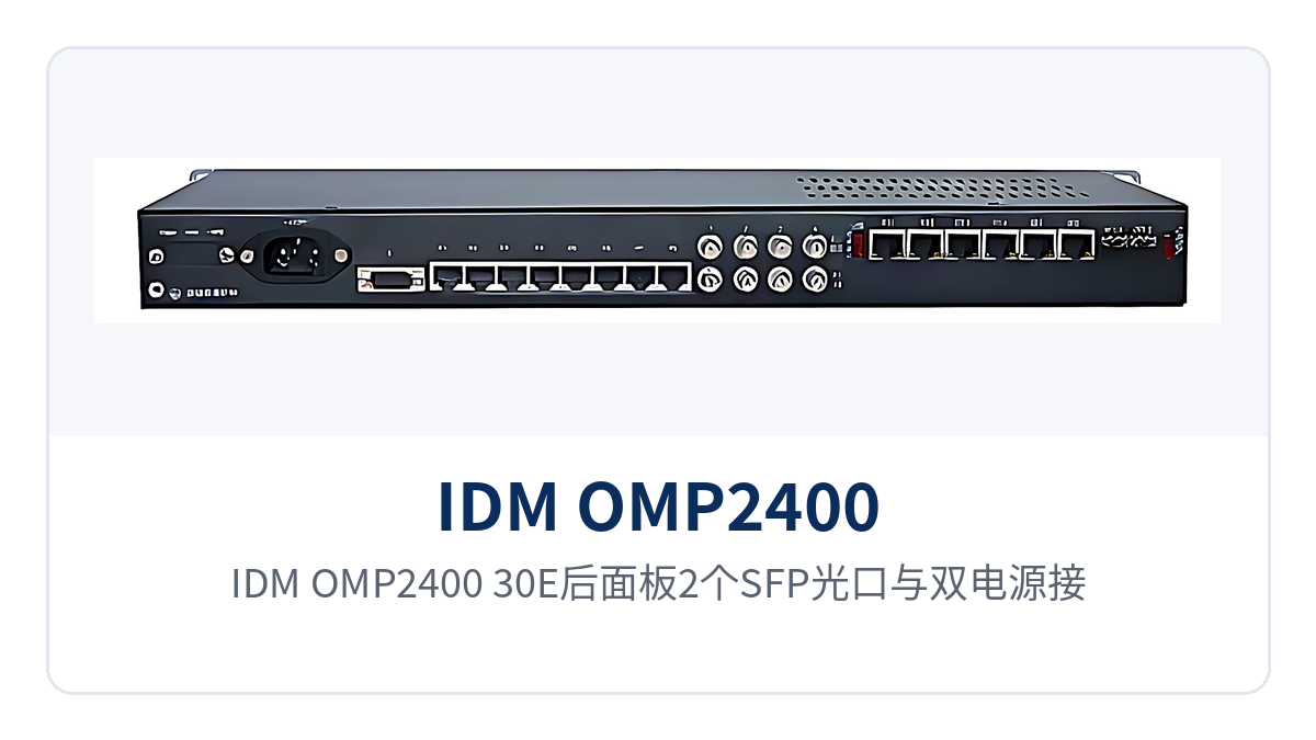
Figure 3: Rear panel layout of the two SFP optical ports and dual power connectors on the IDM OMP2400-30E
Typical Application Scenarios
As a multi-service optical multiplexer, the IDM OMP2400-30E is mainly deployed in three types of private networks: electric power and energy, rail transit, and military and government. What they have in common is the need to send telephones, E1, isolated data and video back to the center over a pair of optical fibers, without accepting long downtime. Raytrans addresses the needs of different industries by presenting this optical multiplexer with flexible networking capabilities, supporting scenarios such as government private network optical fiber communication solutions, military emergency communications vehicle solutions and smart mining communication solutions.
Electric Power and Energy Private Networks
Substations, power plants and distribution automation sites need to transmit dispatch telephones, automation E1 leased lines and in-station data networks simultaneously. One IDM OMP2400-30E is installed at each site, using a pair of 2.5G optical fibers to multiplex inter-station dispatch audio, E1 leased-line channels and isolated Ethernet for transmission, and the central side can receive all services over a pair of optical fibers. The telephone interfaces directly connect to dispatch voice channel equipment in accordance with ITU G.711 A-law and a loop current of 25mA per channel, and 4 groups of E1 transparent transmission free the automation equipment at the opposite end from configuration changes; with 1+1 protection for optical ports enabled, services are automatically switched over to the spare fiber core when any section of the inter-station optical cable is interrupted.
Rail Transit Communications
Metro and conventional railway stations along the line and tunnel sections, as well as expressway toll stations and monitoring sub-centers, need to aggregate telephones, E1 trunks, video surveillance and network data along the line back to the central equipment room. One IDM OMP2400-30E at each site along the line simultaneously connects telephone voice channels, E1 leased lines, HDMI video and network data, which are sent to the center over 2.5G optical fibers. The device supports DC-48V/AC220V dual power supply and an overall power consumption of ≤100W, making it suitable for long-term operation in unattended equipment rooms along the line; 6 physically isolated Ethernet interfaces let surveillance, office and dispatch networks each use independent ports and do not interfere with one another.
Military and Government Private Networks
Field training sites, emergency command posts and government classified equipment rooms emphasize multi-purpose use in one device and reliable operation. A single IDM OMP2400-30E carries 30 telephone channels, 4 groups of E1, 6 isolated Ethernet interfaces and HDMI video at the same time, reducing the number of devices and cable deployment, and only one 1U device needs to be moved during relocation and deployment. 1+1 protection for optical ports ensures that command and dispatch telephones are not interrupted when a single optical fiber fails, and dual power supply supports both DC-48V and AC220V equipment room conditions, making it easy to operate on vehicle-mounted or emergency power and meeting the requirements of military emergency communications vehicle solutions for rapid deployment and high reliability.
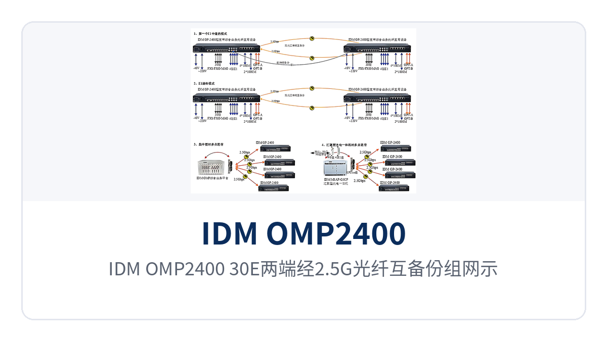
Figure 4: Schematic of mutual backup networking between two IDM OMP2400-30E ends over 2.5G optical fibers
Differentiated Value: What Multi-Service over a Single Fiber and Physical Isolation Bring
The differentiated value of the IDM OMP2400-30E centers on three aspects: optical path redundancy, service convergence and network isolation, each corresponding to on-site benefits as shown in the table below:
Differentiated Selling Point | Value to Users |
|---|---|
2.5G optical port 1+1 dual-fiber mutual backup, private network services uninterrupted | When the primary optical fiber breaks or the optical module degrades, services are automatically switched over to the spare fiber core, and dispatch telephones, E1 leased lines and Ethernet connections require no renegotiation, reducing on-site emergency repair and downtime |
30 telephone channels + 4 groups of E1 transparent transmission, multiple services converged in one device | Voice, E1 leased lines, isolated data and HDMI video are all handled within a 1U chassis, replacing the stacking of multiple single-function devices and reducing rack position occupation and cable patching |
6 physically isolated Ethernet interfaces (2×1000M+4×100M) for security | Each group of ports has independent bandwidth and does not share forwarding resources, so surveillance, office, dispatch and production data can be carried in separate zones, meeting the isolation requirements of electric power, rail transit and classified networks |
How to Select an Optical Multiplexing Equipment
How to select optical multiplexing equipment can be closed out by checking four items one by one: number of service channels, optical fiber conditions, redundancy requirements and power supply environment. First, count the number of service channels: confirm the number of telephone channels (the IDM OMP2400-30E provides 30, with FXO/FXS/magneto options), the number of E1 channels (1-4), the number of Ethernet ports and whether physical isolation is required, and whether HDMI video is transmitted; if the type or number of interfaces does not match, change the model or add boards. Then check the optical fiber conditions: single-mode or multi-mode, 1310nm or 1550nm wavelength, and the link loss budget, and determine the distance grade of the SFP optical module based on a transmit optical power of -1~-3dBm and a receiver sensitivity better than -24dBm.
Next, confirm the redundancy requirements: enable 2.5G optical port 1+1 protection for lines where the inter-station optical cable is prone to damage, with the two optical ports acting as hot standby for each other; for scenarios where only a single optical cable is available, at least reserve spare optical modules and spare parts. Finally, check the power supply and environment: DC-48V, AC220V or dual power supply must match the site power supply, the overall power consumption is ≤100W, the operating temperature is 0℃~40℃ and the humidity is ≤90% (non-condensing); installation in a standard equipment room or a temperature-controlled cabinet is recommended; for sites with special power supply conditions, state this at the time of ordering and have the optical multiplexer manufacturer confirm the configuration. Raytrans can provide selection recommendations and product showcase support from telephone optical multiplexers to multi-service optical multiplexers for different scenarios such as government private network optical fiber communication solutions, military emergency communications vehicle solutions and smart mining communication solutions.
Conclusion
The 6-group isolated Ethernet telephone optical multiplexer IDM OMP2400-30E, as a multi-service optical multiplexer product under Raytrans, brings together 30 telephone channels, 4 groups of E1 transparent transmission, 6 physically isolated Ethernet interfaces (2×1000M+4×100M) and HDMI high-definition (HD) video onto a pair of 2.5G optical fibers; 2.5G optical port 1+1 dual-fiber mutual backup automatically switches over services when a single optical fiber is interrupted, and DC-48V/AC220V dual power supply with an overall power consumption of ≤100W makes it suitable for multi-service over a single fiber networking in electric power and energy, rail transit, and military and government private networks. In scenarios such as government private network optical fiber communication solutions, military emergency communications vehicle solutions and smart mining communication solutions, this video optical multiplexer can serve as a multi-service over a single fiber access node; during selection, first count the number of telephone, E1, Ethernet and video channels, then calculate the link loss and check the power supply and environmental conditions; for a complete product showcase, networking solution and quotation, please contact Beijing Ruiguang Jiyuan Digital Technology Co., Ltd. (www.rdtcom.com, 010-51668966).

