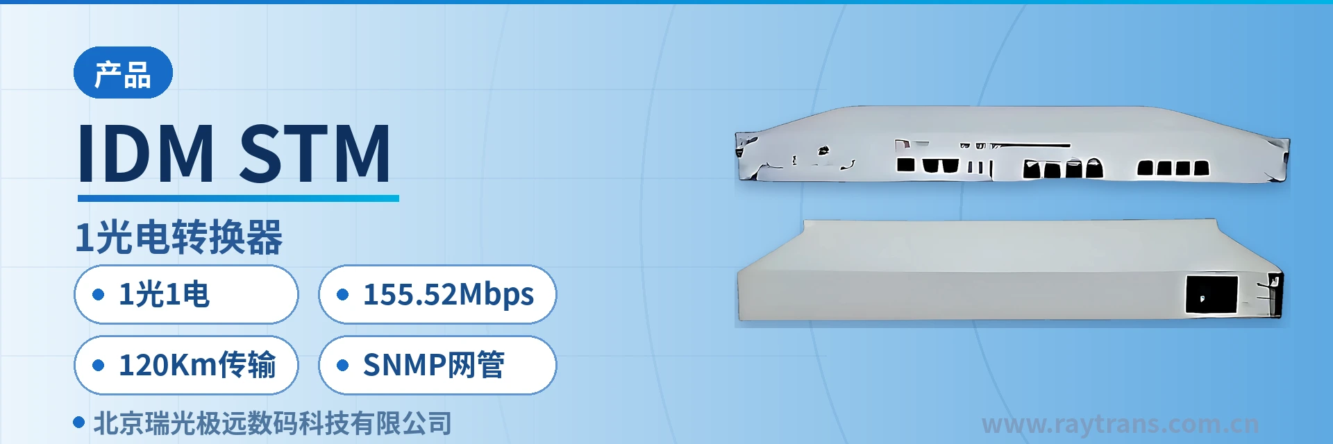
IDM STM-1 Optical-to-Electrical Converter
One optical and one electrical port in a standalone unit completes 155M optical-to-electrical conversion, eliminating the conversion chassis and secondary wiring
The IDM STM-1 Optical-to-Electrical Converter is a new-generation product developed by our company based on SDH technology with independent intellectual property rights. It provides interface conversion from an STM-1 (ATM) electrical interface to an STM-1 optical interface. The STM-1 (ATM) optical-to-electrical converter completes the transmission of STM signals over SDH, or 155M SDH optical-to-electrical conversion, and is suitable for interconnecting various data terminal equipment with 155.520 Mbps interfaces, such as SDH and ATM equipment. Its design follows the ITU-T and Ministry of Information Industry of China specifications on SDH.
An STM-1 optical-to-electrical converter is an interface conversion device that converts STM-1 electrical interface signals into STM-1 optical interface signals. It was developed by Beijing Ruiguang Jiyuan Digital Technology Co., Ltd. (Raytrans) based on SDH technology, with the model IDM STM-1 optical-to-electrical converter, and is used to interconnect data terminal equipment with 155.520 Mbps interfaces, such as SDH and ATM equipment. This bridge converter is designed in accordance with ITU-T and Chinese Ministry of Information Industry specifications on SDH, and can serve as an interface-layer supplement within an optical transmission equipment system, serving scenarios such as government private network optical fiber communication solutions.
The IDM STM-1 optical-to-electrical converter provides a standard 1-optical-1-electrical STM-1 interface. A single unit completes 155.52 Mbps electrical-to-optical conversion, so there is no need to add another conversion chassis in the equipment room. The electrical interface complies with G.703 and uses a BNC 75 Ω coaxial connector; the optical interface complies with G.957, with FC/SC/ST interface forms available, and both sides correspond at the same STM-1 rate. As a product from a professional optical multiplexer manufacturer, Raytrans has continued its consistent interface compatibility design as an SDH equipment manufacturer on this model, allowing it to coordinate networking with existing SDH equipment and MSTP equipment.
Service signals enter through the electrical port and are uplinked through the optical port to the SDH/ATM private network. The device performs only interface-layer conversion, and the service format and frame structure remain unchanged. There are no additional requirements for the wiring, clock, or protection configuration of existing equipment, and the equipment room renovation effort is concentrated on one 1U chassis and two patch cords. The product showcase of this bridge converter focuses on plug-and-play interface conversion capability, facilitating rapid deployment in government private network optical fiber communication solutions.
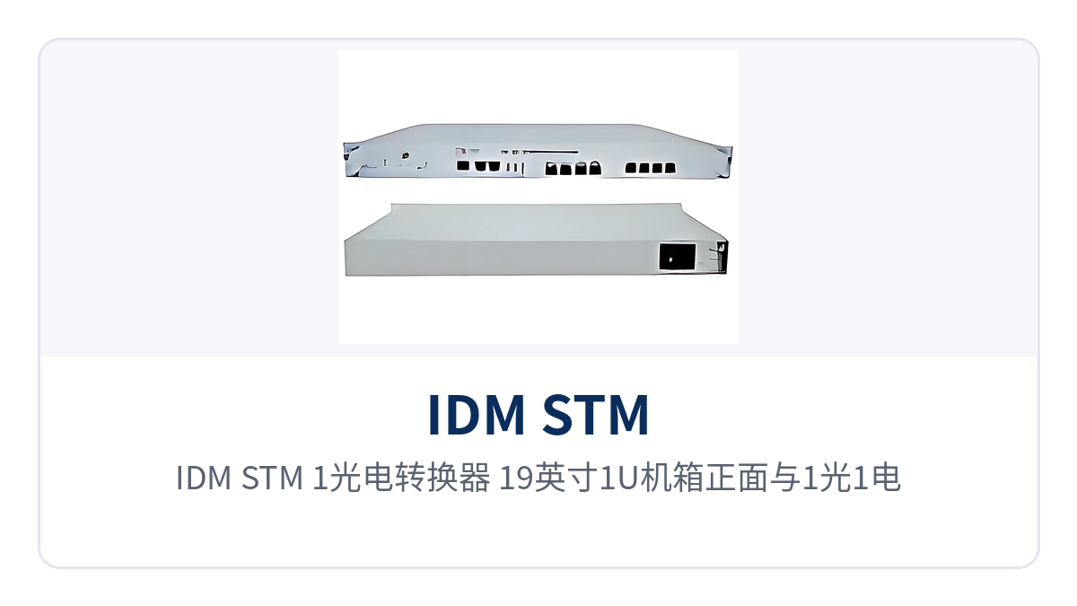
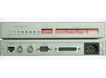
Figure 1: IDM STM-1 optical-to-electrical converter 19-inch 1U chassis front view and 1-optical-1-electrical interface layout
Key specifications at a glance: 1 optical + 1 electrical · 155.52 Mbps · G.703 electrical interface and G.957 optical interface · receiver sensitivity better than -36 dBm · 0-50 Km/120 Km optional · SNMP network management
What on-site problem does the STM-1 optical-to-electrical converter solve?
A large number of SDH and ATM terminals in substations, rail transit section equipment rooms, and private network aggregation points provide only 155.520 Mbps electrical interfaces, while the uplink is an optical cable. The difference in medium and distance requires a device to bridge the gap. The IDM STM-1 optical-to-electrical converter handles exactly this connection: it converts the 155M CMI-coded signal output from the BNC coaxial port into a G.957-standard optical signal and sends it into the optical transmission network. In engineering, such devices are often categorized as bridge converters, used to complete the medium interfacing between electrical and optical ports.
The conversion takes place at the physical interface layer. The device does not rewrite the SDH frame structure or service content; the VC time slots and alarm bytes entering from the electrical port are passed through transparently on the optical port side. The opposite-end SDH equipment still sees a standard STM-1 link, and network management, clock, and protection configurations are all set in the original manner.
A common engineering situation is that a new equipment room already has optical cables laid, while the old equipment provides only electrical ports, or the electrical-port equipment and the optical transmission equipment were purchased in two separate batches. Using one 1U device to complete electrical-to-optical conversion saves both the footprint of an intermediate chassis and an additional cabling run and transition point. In procurement and drawing communication, terms such as SDH optical-to-electrical converter and 155M optical-to-electrical converter are often used to describe the same type of device; final verification is still based on three parameters: interface standard, rate, and transmission distance. During selection, you can also check the product showcase documentation of SDH equipment manufacturers item by item.
Key specifications and interface specifications
The parameters are divided into two parts, the electrical interface and the optical interface, and are listed item by item in the table below for easy verification together with the opposite-end equipment, optical modules, and patch cords. Items marked with applicable conditions in the table are selected according to on-site tiers; unmarked items follow standard values. The wavelength, transmit optical power, and transmission distance rows are interrelated and should be confirmed as a group during selection.
| Item | Parameter/Specification | Description/Applicable Conditions |
|---|---|---|
| Equipment form factor | 19-inch 1U standard chassis | Rack-mounted installation, standard 1-optical-1-electrical STM-1 interface |
| Electrical interface standard | G.703 | ITU-T G.703 155520 kbps electrical interface specification |
| Electrical interface rate | 155.52 Mbps | Consistent with the STM-1 frame rate |
| Electrical interface line coding | CMI code | Electrical port line coding method |
| Electrical interface impedance | 75 Ω | Used with coaxial cable and BNC connector |
| Electrical interface type | BNC | 75 Ω coaxial connector |
| Optical interface standard | G.957 | ITU-T optical interface specification |
| Optical interface rate | 155.52 Mbps | Consistent with the electrical interface rate |
| Optical interface wavelength | 1.31/1.55 μm | Selected according to optical module tier |
| Optical interface transmit power | -9 dBm/-5 dBm | Corresponds to the wavelength tier |
| Optical interface receiver sensitivity | Better than -36 dBm | Reference for receive margin in the link loss budget |
| Transmission distance | 0-50 Km/120 Km optional | 120 Km is the long-distance tier, selected according to the link budget |
| Optical interface type | FC/SC/ST, etc. | Selected according to the equipment room patch cord interface |
| Power supply | DC -48 V/AC 220 V optional | Communications equipment room DC busbar or sites without a DC distribution panel |
| Network management | SNMP network management and monitoring and alarm | Status monitoring and alarm reporting |
| Operating temperature and humidity | not yet recorded in the knowledge base | Subject to the manufacturer's technical documentation and the accompanying instructions |
The 75 Ω impedance and CMI code of the electrical interface are the fixed pairing for an STM-1 electrical port, used with 75 Ω coaxial cable and BNC connectors, and are not interconnected with 120 Ω twisted pair; otherwise, return loss and bit error rate will both degrade. The shielding layer of the coaxial cable is grounded at one end according to the equipment room grounding specification to avoid introducing ground loop interference into the 155M electrical signal.
The optical interface side is selected according to link length: the 0-50 Km tier is suitable for short- and medium-distance links within a station or between stations, while the 120 Km transmission tier, combined with 1.55 μm wavelength and higher transmit optical power, is used for long-distance private network backbones and cross-region nodes. Receiver sensitivity better than -36 dBm indicates that there is still receive margin when the link loss budget is tight; the specific margin is calculated section by section according to optical cable attenuation, the number of connectors, and splice points.
Power supply and structure are selected according to equipment room conditions: DC -48 V is suitable for power supply from the DC busbar of a communications equipment room, AC 220 V is suitable for sites without a DC distribution panel, and the 19-inch 1U standard chassis can be installed directly into an existing standard rack and deployed in the same cabinet as SDH equipment. As an interface conversion product commonly supplied by optical multiplexer manufacturers, this model can be used in combination with MSTP and SDH equipment in the selection of optical transmission equipment accessories.
What functions and SNMP network management bring
The functions cover five aspects: interface conversion, loopback test, status indication, network management alarms, and power supply structure. Each item corresponds to a specific on-site operation or a remote judgment, and they are listed item by item in the table below for reference during acceptance and troubleshooting. The loopback and network management items are used together and cover most remote troubleshooting steps.
| Function | Description |
|---|---|
| 1-optical-1-electrical STM-1 interface | One STM-1 electrical interface and one STM-1 optical interface; a single unit completes 155.52 Mbps electrical-to-optical conversion |
| Local loopback test | Short-connect the optical port transmit and receive into a loop on the device side to determine whether the local optical module and optical path are normal |
| Remote loopback test | Set a loop at the remote node through network management to determine whether the entire optical link and the opposite-end access are normal |
| Operating status indication | The front panel provides power, optical port, electrical port, and alarm status indications for direct on-site interpretation |
| SNMP network management and monitoring and alarm | Supports SNMP network management, reports link and device alarms, facilitating centralized monitoring and unattended operation |
| Power supply options | Two power supply modes, DC -48 V and AC 220 V, selected according to equipment room conditions |
| 19-inch 1U structure | Standard rack installation, can be deployed in the same cabinet as SDH equipment |
SNMP network management collects link status and alarms to the NMS platform, so O&M personnel in the central equipment room can see statuses such as no optical receive at the remote site's optical port or loss of signal at the electrical port, without sending personnel to the site each time for confirmation. For unattended substations and rail transit section equipment rooms, this remote visibility is the foundation of routine maintenance.
How do local loopback and remote loopback locate faults?
Loopback tests are used to determine whether a fault lies in the local device, the optical cable link, or the opposite-end access; the two loopback types cover different scopes. On site, test section by section in the order of local first and remote second to isolate the faulty section and avoid back-and-forth troubleshooting of the entire link. Both loopback types are performed on the device front panel and on the network management side, without the need to go to the equipment room to disconnect and reconnect patch cords.
- First perform a local loopback at the near end by looping the optical port transmit and receive. At this point, the electrical port service should be able to loop back. Normal return indicates that the local device and electrical interface are working properly, and the problem points to the optical path or the opposite end.
- Then perform a remote loopback at the remote node through SNMP network management by looping the remote optical port transmit and receive. If the near end can see the signal return, the optical cable link and the remote optical module are available.
- If both loopbacks are normal but the service still does not work, the fault scope narrows to the service configuration and cabling on the opposite-end electrical interface side; check item by item according to the interface status and alarms of the opposite-end device.
Loopback is a maintenance operation. During the test, the 155M service in this direction is temporarily unavailable, so schedule it during a low-traffic window. After the remote loopback ends, confirm on the network management system that the loopback has been removed before restoring the service, to avoid the link remaining in a self-loop state for a long time.
Typical application scenarios
Electric power private network: 155M channel from substation to dispatch center
Protection, automation, and metering devices in a substation are mostly aggregated through SDH equipment, and a section of optical cable lies between the in-station electrical-port equipment and the dispatch center. The IDM STM-1 optical-to-electrical converter is installed in the in-station communications cabinet, converting the electrical port signal into an optical signal and sending it over optical cable to the dispatch center, without changing the original in-station wiring.
Electric power sites are distributed and mostly unattended, so remote visibility of device status directly affects emergency repair efficiency. SNMP network management and monitoring and alarm report optical port and electrical port status to the dispatch-side network management system; together with remote loopback, on-duty personnel can determine at the center whether the fault lies in the station or in the optical cable, and then decide whether to send personnel.
Rail transit: electrical-to-optical connection between the communications backbone and section nodes
The communications backbone of a rail line is mainly an SDH ring network, and connections between section equipment rooms and stations rely on optical cables; some terminals in the section still provide only 155M electrical interfaces. The IDM STM-1 optical-to-electrical converter completes electrical-to-optical conversion in the section equipment room and connects section services to the backbone ring network.
Section equipment rooms have limited space and maintenance windows concentrated at night; the 19-inch 1U chassis and front panel status indications facilitate rapid installation and inspection. Local loopback and remote loopback cover the troubleshooting needs of section links, and with SNMP network management, most judgments can be completed at the control center.
Military and government private network: connecting existing electrical-port equipment to optical transmission
Private network equipment rooms often contain SDH and ATM equipment that has been in use for many years, with 155.520 Mbps electrical interfaces, while newly built transmission links all use optical cables. The IDM STM-1 optical-to-electrical converter completes interface conversion according to both G.703 and G.957 standards, and its standards compliance allows direct access to the SDH/ATM private network; it can connect existing electrical-port equipment without changing the private network's original frame structure and service configuration. In the overall design of government private network optical fiber communication solutions, such interface conversion equipment is often deployed together with MSTP and SDH equipment, and Raytrans can provide the corresponding product showcase and technical documentation for selection reference.
Private network links are often long-distance and cross-region; optical interface sensitivity better than -36 dBm and the 120 Km transmission tier provide margin for long-distance links. Fault location on long-distance links is costly, and remote loopback and SNMP alarms move troubleshooting actions forward to the central equipment room, reducing the number of site visits.
Deployment and wiring key points
On-site deployment is carried out in the order of interface, power supply, grounding, and network management; a different order easily leads to repeated troubleshooting after power-on. Before wiring, first verify the opposite-end interface form and optical module tier, and power on only after confirmation, to avoid disconnecting and reworking after power-on and to avoid the optical port receiving mismatched optical power for a long time. As an optical multiplexer manufacturer, Raytrans emphasizes this construction order in the product showcase of both bridge converters and SDH equipment.
- Connect the electrical interface to the 155M electrical port at the opposite end using a 75 Ω coaxial cable with BNC connectors. Determine the cable length according to the cabling route in the equipment room, tighten the connectors, and label them properly.
- Select FC/SC/ST adapters for the optical interface according to the patch cord interface form, with the receive and transmit directions crossed accordingly. After insertion, confirm that the latches are fully engaged and that there are no foreign objects in the optical port.
- Connect the power supply to DC-48V or AC220V according to the equipment room conditions. Verify the power supply polarity before wiring; the positive and negative poles of DC-48V must not be reversed.
- After power-on, observe the power and interface status indications on the front panel. Once normal, configure the SNMP network management address and alarm reporting targets.
- Before service provisioning, perform a local loopback and a remote loopback to confirm that both the link and the device are normal, then remove the loopbacks and put the link into operation.
Four Conditions to Confirm for Selection and Purchase
For the same model, the differences in combinations across sites concentrate on four items: distance, wavelength, optical interface form, and power supply. Finalize these four items before purchase, and the equipment can be installed directly upon arrival. Any item that does not match the site will cause one more rework and waiting period. Write the four conditions into the purchase list and the incoming acceptance sheet, and check them against the same criteria at delivery. When supplying optical transmission equipment, SDH equipment manufacturers usually also use these four items as the baseline for selection verification.
- Transmission distance: Select between the 0-50Km and 120Km options according to the actual inter-station optical cable length and loss budget. For the long-distance option, confirm the optical module wavelength at the same time.
- Optical interface form: Select FC, SC, or ST according to the existing patch cords in the equipment room. Mixed use requires additional fiber adapters; the fewer the adapter points, the more stable the link.
- Power supply mode: Select DC-48V for equipment rooms with a DC busbar, and AC220V for sites without a DC distribution panel.
- Network management access: Confirm that the NMS platform supports SNMP, and reserve the management address and alarm reporting channel for the device.
Conclusion
The IDM STM-1 optical-to-electrical converter performs 155.52Mbps electrical-to-optical conversion in a compact one-optical-one-electrical form. The dual G.703 and G.957 standards ensure that the link can be directly connected to an SDH/ATM private network. Sensitivity better than -36dBm and the 120Km transmission option cover long-distance private network links, while local and remote loopbacks together with SNMP network management move fault location forward to the central equipment room.
For sites in electric power, rail transit, military and government private networks that still use 155M electrical port equipment, the IDM STM-1 optical-to-electrical converter is a cost-controllable optical fiber access path: it does not change existing service configurations and completes the electrical-to-optical connection on a single 1U device, with access and maintenance performed through standard interfaces. In government private network optical fiber communication solutions, this device can coordinate networking with MSTP and SDH equipment. As an optical multiplexer manufacturer, Raytrans provides complete product showcase and technical support around products such as bridge converters.