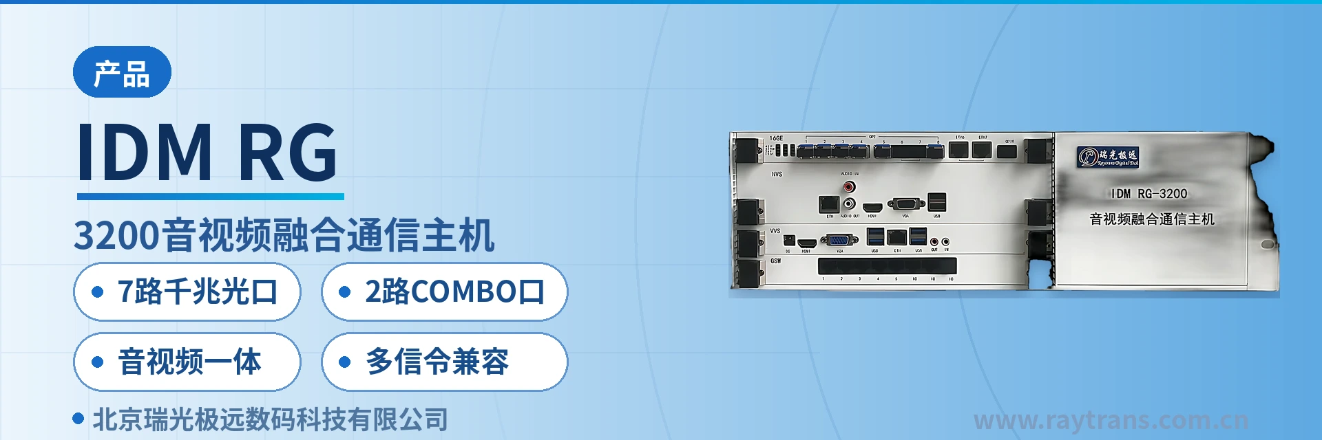
IDM RG-3200 Audio and Video Converged Communication Host
9 gigabit optical ports for direct multi-node connection, voice and video switching in one chassis, panel LEDs for locating broken fibers
The IDM RG3200 audio converged dispatching exchange is a PBX/IPPBX converged communication device developed and designed by Raytrans, carefully built for telecom carriers, government, industries and large and medium-sized enterprise users, and powerful in function. The product is designed with advanced digital integrated circuits, a highly integrated optimized structure and PBX/IPPBX communication technology. It can be deployed on the enterprise side or in a carrier equipment room, providing users with an integrated solution that converges audio and video into one. The system adopts a modular design and board-based assembly, and supports PRI, NO.1, NO.7, SIP/H.323
The IDM RG-3200 Audio and Video Converged Communication Host is an audio and video dispatching device built on the PBX/IPPBX converged communication equipment architecture. Developed by Raytrans, it combines voice switching, video processing and gigabit Ethernet (GE) aggregation into a single 3U plug-in board device in a private network equipment room, and it is the device that undertakes the core audio and video dispatching and converged dispatching tasks in a converged communication command and dispatch system.
The unit is assembled from modular boards. Main control, trunk, trunking, audio, video and switching functions each occupy their own plug-in board, so capacity grows or shrinks with the business and there is no need to replace the whole unit for expansion. The device supports PRI, NO.1, NO.7 and SIP/H.323 signaling, connects upward to carrier VoIP softswitch platforms, and connects downward to public switched telephone network (PSTN) voice channels, analog telephones, trunking radio sets and network cameras, meeting the product showcase and multi-network convergence access requirements of command and dispatch scenarios.
Key Specifications at a Glance: 7 gigabit optical ports · 2 COMBO ports · integrated audio and video · multi-signaling compatibility · 16-port gigabit switching · 100 concurrent calls
What Kind of Device Is an Audio and Video Converged Communication Host?
An audio and video converged communication host is a dispatching device that integrates telephone switching, video access and Ethernet switching in one chassis. Its core role is to gather scattered voice terminals, video resources and private network links onto one platform for unified dispatching. For private network users it simultaneously acts as a telephone exchange, an audio and video dispatching center and an optical port aggregation node, and it is also the core bearer device of a converged communication command and dispatch system on the equipment room side.
The IDM RG-3200 takes cards on demand inside one 3U chassis: add a trunk board when voice channels are insufficient, add a video processing card when video is insufficient, add a switching card when optical ports are insufficient — capacity expansion means adding boards rather than replacing the unit. The boards and the backplane are connected over gigabit Ethernet, and voice, video and data traffic inside the chassis is switched within the unit, providing a unified audio and video dispatching foundation for upper-layer converged dispatching services.
The unit is divided into nine board types by service, and the configuration is ticked on site according to the number of voice channels, the trunking standard and the number of video channels. Each function item and its role are listed one by one in the table below; during selection, compare them item by item against the service list. Trunk, trunking, audio and video cards are added or removed according to service volume, so nothing is missed and no extra chassis slots are occupied.
| Function Item | Function Description |
|---|---|
| Dispatch service main control board (MAIN) | Runs the LINUX switching system and the converged command and dispatch, converged communication service, publishing service and consultation service software, and undertakes signaling processing and dispatching logic |
| Loop-start trunk board (8FXO) | A single board provides 8 loop-start trunk interfaces for connecting subscriber lines from the central office or an upper-level exchange, and supports FSK and DTMF caller ID detection |
| Loop-start subscriber board (8FXS) | A single board provides 8 loop-start subscriber interfaces for analog telephones, fax machines and other terminals, and supports FSK and DTMF caller ID detection |
| Trunking access board (4AU) | Supports 4 trunking interfaces for connecting 350M, 300M, 800M and HF/VHF/UHF trunking systems, and interworks voice with public network mobile phones, IP phones and mobile apps |
| Audio access board (4EM) | Supports 4 audio interfaces, each connecting one mixer, microphone or conference terminal, bringing venue sound into the IP communication system |
| 16GE gigabit Ethernet aggregation switching card | 16 gigabit switching ports on the card, with 7 SFP gigabit optical ports and 2 optical/electrical COMBO ports on the front panel, aggregating the 8 gigabit ports of each plug-in board toward the backplane |
| GSW gigabit Ethernet switching card | 8 gigabit switching ports on the card, with 5 10M/100M/1000M electrical ports on the front panel, providing 1 gigabit uplink to the backplane aggregation card |
| NVS video processing card | Connects ONVIF and RTSP network cameras, supports mixed access of H.265 and H.264, 6-megapixel preview, storage and playback, and same-source HDMI and VGA output |
| VVS audio and video processing and switching card | Provides AUDIO IN/OUT, HDMI, VGA, USB2.0 and 100M Ethernet ports, and undertakes audio and video processing and switching |
Three differentiated values are concentrated in this chassis: optical port density determines whether multiple nodes can be connected directly, in-chassis convergence determines how many devices sit in the equipment room, and panel indication determines how long fault location takes when the site is unattended. They are listed one by one in the table below for item-by-item comparison with the project requirements document.
| Differentiation Point | Value to Private Network Customers |
|---|---|
| 9 gigabit SFP optical ports + 2 COMBO ports | Optical port density suits multi-node aggregation on private networks: the 9 gigabit optical port positions on the front panel consist of 7 1000Base-X SFP ports and 2 COMBO ports, so nodes in multiple directions can enter the host directly and the equipment room no longer needs an additional external aggregation switch; the unit is suited to serving as an aggregation node in a government private network optical fiber communication solution |
| Audio/video/Ethernet switching converged in one unit | Less equipment stacking in private network equipment rooms: voice switching, video preview and gigabit switching are completed in the same chassis, one layer of external equipment disappears from the room, and cabling and power supply points are reduced accordingly; product showcase and command and dispatch services can be carried in the same chassis |
| POW power indicator + per-port LINK LED for optical ports | Fast fault location in unattended equipment rooms: check POW for power status, and each of the 9 optical ports has its own LINK LED; when the LED is off it points to the corresponding broken fiber, so guiding on-site personnel by phone to watch the LEDs is enough to locate the fiber core |
How to Read the Front Panel and Rear Panel Interfaces
The front panel is the direct basis for on-site troubleshooting. Optical ports are arranged in rows, each with a LINK indicator beside it, plus a POW power LED and two aggregation status indicator LEDs, IF and OF. On-duty personnel do not need to open the network management system; standing in front of the cabinet they can judge whether the link and the power supply are normal.
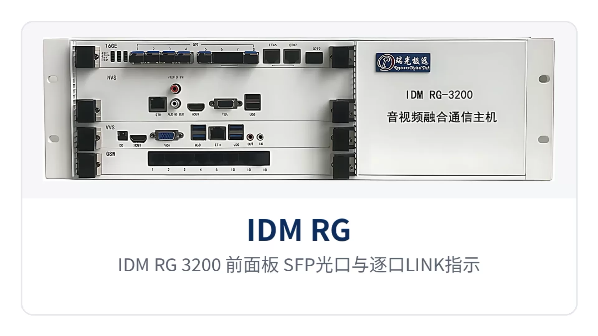
Figure 1: Close-up of the SFP optical ports and per-port LINK indicators on the IDM RG-3200 front panel
Panel markings are grouped by interface: on the switching card side are OPT optical ports, ETH electrical ports and LED indicators, while on the video and audio and video processing card side are AUDIO IN/OUT, HDMI, VGA, USB and ETH ports. Every plug-in board carries silkscreen markings; check them one by one against the panel description before wiring and you will do less rework.
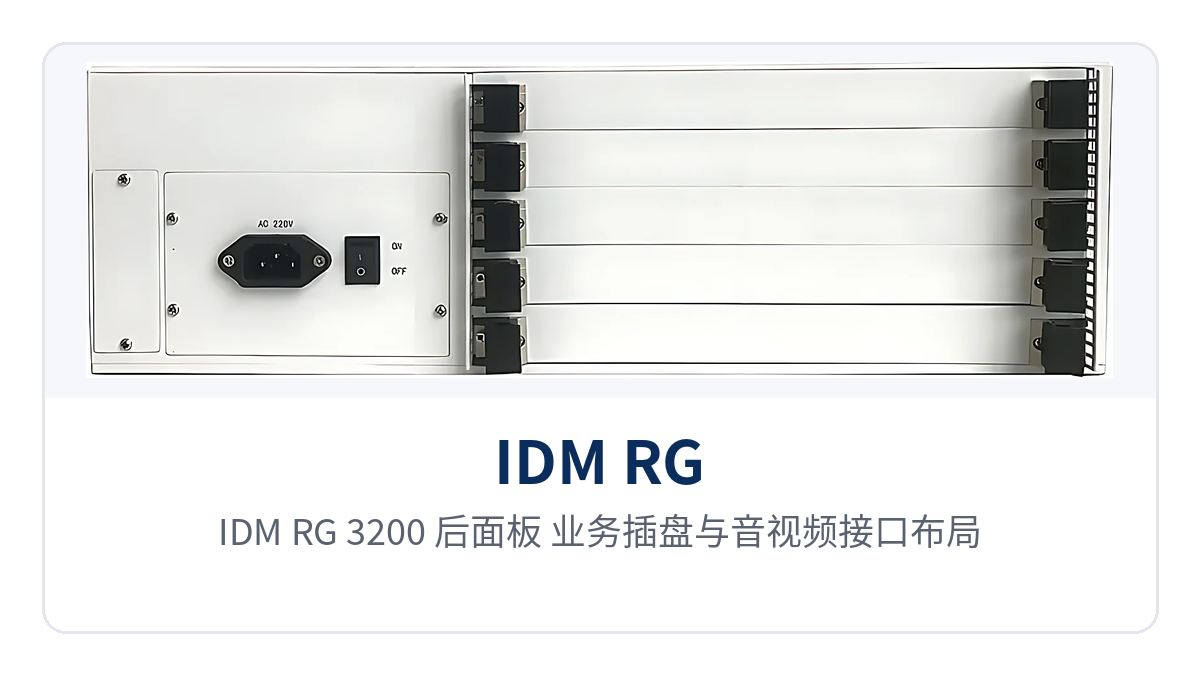
Figure 2: Layout of the service boards and audio and video interfaces on the IDM RG-3200 rear panel
Power and link status can be read directly from the panel: POW on means the power supply is energized normally and off means a power supply fault; the LINK LEDs of OPT1 to OPT9 on mean the fiber connection of the corresponding port is normal and off means an optical fiber break. IF and OF reflect the total connection of the backplane gigabit ports and the total switching connection of the external optical ports respectively.
Key Specifications
The table below lists structure, interface, signaling and capacity parameters for the unit as a whole, with data taken from the original product documentation and the panel description. Supply is subject to the contract configuration; items without a stated tolerance are subject to the technical documentation supplied with the unit. During on-site verification, check the number of optical and electrical ports first, then the signaling and concurrency capacity.
| Item | Parameter/Indicator | Description/Applicable Conditions |
|---|---|---|
| Structure | Rack-mounted 3U plug-in board chassis | Board-based assembly, plug-in boards selected according to service |
| Gigabit optical ports | OPT1-5, OPT8, OPT9, 7 × 1000Base-X SFP in total | Optical modules selected according to on-site link distance |
| Optical/electrical COMBO ports | OPT6 with ETH6, OPT7 with ETH7, 2 in total | Optical and electrical ports multiplexed, selected according to on-site cabling conditions |
| Electrical ports | 5 × 10M/100M/1000M on the GSW card front panel | Connect local network management, dispatch consoles or office network terminals |
| In-chassis switching | 16 gigabit switching ports on the 16GE card, 8 on the GSW card | Each plug-in board uplinks to the backplane at gigabit rate, and switching is completed inside the unit |
| Audio interfaces | AUDIO IN, AUDIO OUT; 4 audio channels on the 4EM board | Connect mixers, microphones and conference terminals |
| Video interfaces | HDMI (3840×2160/30Hz), VGA (1920×1080/60Hz), USB2.0 | HDMI and VGA output from the same source |
| Signaling | PRI, NO.1, NO.7, SIP/H.323 | Can connect to PSTN and carrier VoIP softswitch platforms |
| Protocols | SIP2.0/TFTP/FTP/SNMP/TELNET/HTTP/IEEE802.1Q/IEEE802.1X/RTSP | Network management and video stream access are networked according to these protocols |
| Concurrency and registration | 100 concurrent calls, 500 user registrations | Number of concurrent channels and registrations selected according to user requirements |
| Voice encoding and decoding | G.711, G.726, G.729a/b, G.723, iLBC | Negotiated between trunk boards and terminals |
| Video encoding | Mixed access of H.265 and H.264 | Connects ONVIF and RTSP network cameras, supports 6 megapixels |
| Host configuration | Quad-core processor, 4G DDR3, 1T storage, 220V single power supply, gigabit NIC | Rack-mounted installation; the specific configuration is subject to the contract |
| Operating environment | Not yet recorded in the knowledge base | Subject to the technical documentation supplied with the unit |
As a command and dispatch system manufacturer, Raytrans draws on the chassis capabilities described above to provide selection and networking support for converged communication command and dispatch systems in government private network optical fiber communication solutions and military emergency communications vehicle solutions, placing audio and video dispatching, command and dispatch and converged dispatching in one and the same device.
Which Signaling Is Supported and How to Connect PSTN and Carrier Platforms
Signaling compatibility determines whether an audio and video dispatching host can enter an existing telephone network. The IDM RG-3200 supports PRI, NO.1, NO.7 and SIP/H.323 at the same time, so legacy and new networks can coexist on the same device and there is no need to cut over the whole telephone network at once during a migration.
On the access side, boards are chosen according to line conditions; analog lines, digital trunks and IP trunks each have their own applications, so first confirm whether the central office provides a subscriber line or a digital trunk, then decide the board and the signaling. There are three common paths on site, and choosing the wrong standard directly affects whether calls can be dialed in:
- Analog trunk: use the 8FXO board to connect central office subscriber lines and make and receive calls in loop-start trunk mode, suitable for equipment rooms with few voice channels and older lines;
- Digital trunk: use PRI or NO.7 to connect to the carrier's exchange; when call volume is high and the calling party number has to work together with signaling, plan for a digital trunk;
- IP trunk: use a SIP trunk to connect to third-party softswitch platforms and video conferencing systems, saving long-distance voice channels in cross-regional networking.
In terms of reliability, the host offers dual-unit backup capability and supports multi-unit cascading for capacity expansion. Conference functions on the dispatch console side cover session setup, adding members, granting or revoking speaking rights, locking the session, broadcast and recording; when video conferencing is restricted, fixed-line telephones and mobile phones can still be brought into the audio conference, meeting the voice interworking requirements of converged communication scenarios.
How to Network 9 Gigabit Optical Ports and Aggregate Multiple Private Network Nodes
Multi-node aggregation on a private network relies on the 9 gigabit optical port positions on the front panel: OPT1 to OPT5, OPT8 and OPT9 are 1000Base-X SFP optical ports, while OPT6 with ETH6 and OPT7 with ETH7 form two COMBO ports, with the optical or electrical port chosen according to on-site conditions. In this way one host presents 9 gigabit optical directions to the outside, providing ample link aggregation capability for a government private network optical fiber communication solution.
In-chassis switching is handled by the 16GE aggregation card: 16 gigabit switching ports on the card, aggregating the 8 gigabit ports coming up from each plug-in board toward the backplane and providing 1 gigabit to the 3U plug-in board backplane; the GSW switching card in turn provides 5 10M/100M/1000M electrical ports to the outside so local terminals can connect nearby.
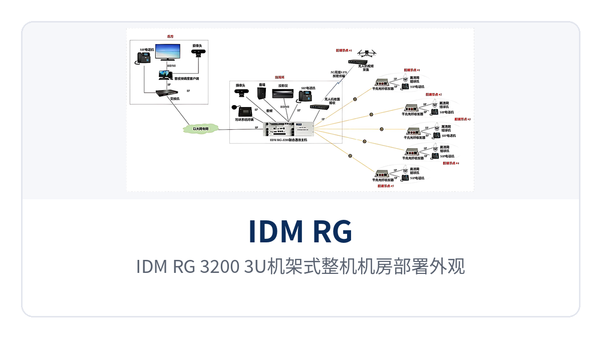
Figure 3: Exterior of the IDM RG-3200 3U rack-mounted unit as deployed in an equipment room
During networking, the 9 optical ports can be pointed at nodes in different directions — the command center to district and county nodes, substations and rail transit stations each take one — and switching is completed directly inside the unit, so the equipment room no longer needs a separate aggregation switch. The number of optical ports corresponds one-to-one with the number of directions; before adding directions later, check the remaining capacity first and then decide the plan.
Typical Application Scenarios
Government Emergency Command Private Network: One Host Replaces a Cabinet of Equipment
Emergency command private network equipment rooms are short of space and full of equipment, with telephone switching, video conferencing, video wall monitoring and link aggregation each usually occupying a separate device. The IDM RG-3200 packs voice switching, video processing and 9-port gigabit optical aggregation into the same 3U chassis, removing one layer of equipment stacking from the room and reducing cabling and power supply positions accordingly; it is a highly integrated choice in government private network optical fiber communication solutions.
The command center runs fiber to district and county nodes, with each optical port corresponding to one direction, so the on-duty operator knows from the LINK LEDs which path is interrupted. On the venue side, the 4EM audio access board brings the mixer and microphone in, and the dispatch console sets up and starts a conference directly, with several departments talking in the same conference; the voice and video collaboration of the converged communication command and dispatch system is fully demonstrated in this scenario.
Electric Power and Energy Private Network: Panel-Based Fault Location at Unattended Substations
Substations and centralized control stations are far apart and numerous, and the communications equipment room is unattended all year round. The IDM RG-3200 gives each of the 9 optical ports its own LINK LED and uses the POW LED to indicate power status, so when on-duty personnel guide on-site staff by phone to watch the LEDs they can tell whether the fiber is broken or the power is out without opening the cabinet first.
Electric power dispatch telephones must be available for long periods; the host supports dual-unit backup and multi-unit cascading, so expansion only requires adding boards or paralleling units rather than replacing the whole machine. The trunking access board can bring 350M and 800M trunking systems in, so intercom voice from an emergency repair site can return to the dispatch console — converged dispatching capability is especially critical in electric power emergency scenarios.
Rail Transit Communication Private Network: Direct Multi-Node Optical Ports Eliminate External Switches
Rail private networks have many stations along the line and tight optical fiber resources, and adding an external switch at every station creates an extra point of failure and more maintenance workload. The IDM RG-3200 front panel has 7 1000Base-X SFP ports plus 2 COMBO ports, so the fiber from each station along the line can enter the host directly, and 16 gigabit switching ports inside the unit complete the aggregation.
Broadcast, video and telephone services on the station side can be connected within the same host: the NVS video processing card connects the platform camera, the 4AU trunking access board brings 350M or 800M trunking systems in, and a one-touch call from the dispatch console reaches the station. The equipment room records lose one category of external device and routine inspection items decrease accordingly, with audio and video dispatching and command and dispatch services running together on the same platform.
The equipment room of an emergency command private network is short on space and crowded with equipment, where telephone switching, video conferencing, video wall monitoring, and link aggregation often each occupy a separate device. IDM RG-3200 packs voice switching, video processing, and 9-channel Gigabit optical port aggregation into a single 3U chassis, removing one layer of equipment stacking in the equipment room and reducing cabling and power supply positions accordingly. It is a highly integrated choice in government private network optical fiber communication solutions.
The command center runs optical fiber to the nodes of each district and county, with each optical port corresponding to one direction, so the duty operator can tell which link is interrupted just by checking the LINK LED. At the venue side, a 4EM audio access board connects the mixer and microphones, and the dispatch console sets up a conference directly, with multiple departments talking in the same conference. The voice and video collaboration of the converged communication command and dispatch system is fully demonstrated in this scenario.
Electric Power and Energy Private Network: Locating Faults by Panel Indicators at Unattended Substations
Substations and centralized control stations are far apart and numerous, and the communications equipment room is unattended all year round. IDM RG-3200 provides a LINK LED for each of the 9 optical ports and a POW LED to indicate power status, so on-duty personnel can guide on-site staff by phone to check the LEDs and determine whether it is an optical fiber break or a power failure, without opening the cabinet first.
Power dispatch telephone service requires long-term availability. The main unit supports dual-unit backup and multi-unit cascading, and capacity expansion only requires adding boards or paralleling more units, without replacing the complete unit. The trunking access board can connect 350M and 800M trunking systems, so intercom voice from emergency repair sites can return to the dispatch console. Converged dispatching capability is particularly critical in electric power emergency scenarios.
Rail Transit Communication Private Network: Direct Multi-Node Optical Port Connections Eliminate External Switches
The rail transit private network has many stations along the line and limited optical fiber resources, and adding an external switch at each station would increase points of failure and maintenance workload. IDM RG-3200 provides 7x 1000Base-X SFP ports plus 2x COMBO ports on the front panel, so the optical fibers from stations along the line can connect directly to the main unit, and the 16 Gigabit switching ports onboard perform aggregation.
Broadcast, video, and telephone services at the station side can be interconnected within the same main unit: the NVS video processing card connects platform cameras, the 4AU trunking access board connects 350M or 800M trunking systems, and the dispatch console can reach the station with a one-touch call. With one less type of external device in the equipment room records, routine inspection items are reduced accordingly, and audio and video dispatching and command and dispatch services run collaboratively on the same platform.