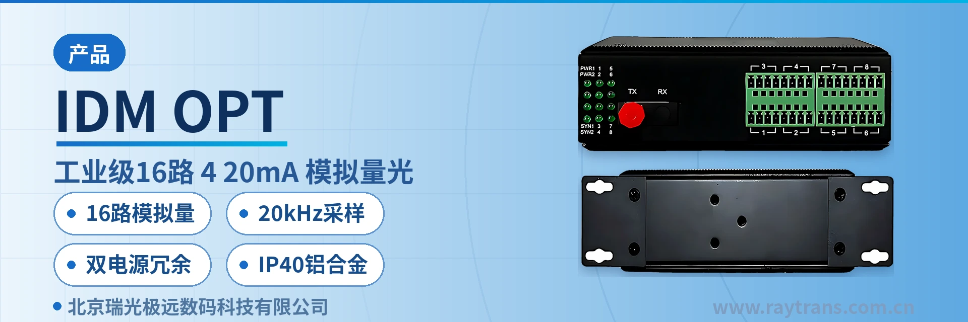
IDM OPT-16AM Industrial-Grade 16-Channel Analog Optical Multiplexer
FPGA parallel 16-channel no queuing, single-fiber synchronous relay, latency <0.1ms per channel
The IDM OPT-16AM device adopts a large-scale FPGA design and proprietary technology to simultaneously support 1 to 16 channels of analog signals (current/voltage) relayed over optical fiber. The device uses dual power supply, a high-performance FPGA programmable device with no MCU processing, high-speed conversion, a sampling frequency of up to 20KHZ, and a 12-bit AD conversion chip. It solves the challenges of electromagnetic interference, ground loop interference, and lightning damage, greatly improving the reliability, safety, and confidentiality of control signals, while also resolving the limited transmission distance of cables.
The IDM OPT-16AM industrial-grade 16-channel 4-20mA analog optical multiplexer is a device that converts on-site current and voltage quantities into optical signals and relays them in pairs over a single optical fiber. It is developed by the optical multiplexer manufacturer Beijing Ruiguang Jiyuan Digital Technology Co., Ltd. (Raytrans) and is used for industrial automation analog remote acquisition in industrial automation, electric power and energy, and rail transit applications. As a mature 4-20mA analog optical multiplexer, the device is also a useful reference in the bridge converter product showcase.
The device adopts a large-scale FPGA parallel architecture with no MCU sequential processing stage. The 16 analog input and output channels can be combined arbitrarily and arranged in any channel order, and a single fiber can perform high-speed synchronous relaying of 16 analog channels, with the two ends used in pairs. Like other models in the optical transceiver product line, this analog optical multiplexer reflects Raytrans's technical accumulation in the field of industrial site signal transmission.
Key specifications at a glance: 16 analog channels · 20kHz sampling · 12-bit AD · latency <0.1ms per channel · dual redundant power supply DC12-48V · power consumption <5W · IP40 aluminum alloy · 0.75kg per unit
What kind of on-site problem does an analog optical multiplexer solve?
The 4-20mA current loop is a common analog transmission method at industrial sites: a sensor converts physical quantities such as pressure, temperature, and liquid level into a 4~20mA current, and the receiver restores the value according to the current magnitude, with 4mA corresponding to the lower range limit and 20mA to the upper range limit; anything below 4mA can be treated as a line break. Current transmitted over long cables does not attenuate with conductor resistance, and its anti-interference capability is better than that of voltage signals, which is why industrial instruments generally use current output.
Long-distance cable transmission encounters three types of problems: inconsistent ground potential at the two ends forms a ground loop current, lightning-induced overvoltage intrudes along the cable, and electromagnetic interference from variable-frequency drives and switchgear is superimposed on the signal, manifesting as jumping acquisition values or even channel damage. Optical transmission converts the electrical signal locally at both ends, with only light on the intermediate link, so the two ends are completely isolated electrically.
The IDM OPT-16AM carries bidirectional relaying of 16 analog channels over a single optical fiber. The AD/DA of the 16 channels are read and written in parallel by the FPGA, with no queuing between channels, latency of less than 0.1ms per channel, and simultaneous acquisition and restoration of multiple signals. To the PLC and DCS, the remote sensors appear as if connected to the local cabinet, and the analog optical multiplexer replaces long-distance cables with an optical fiber link.
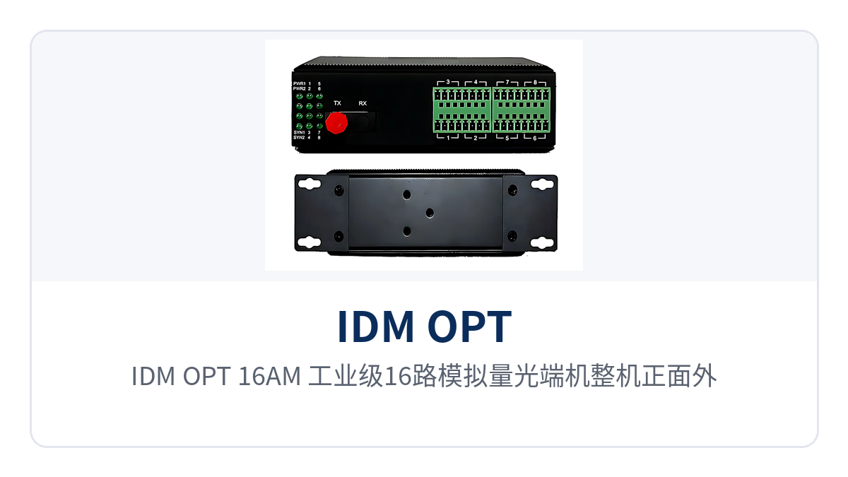
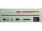
Figure 1: Front appearance of the IDM OPT-16AM industrial-grade 16-channel analog optical multiplexer with power and optical link indicator LEDs
Key specifications and functions at a glance
As an industrial-grade analog optical multiplexer, the unit integrates the optical transceiver unit, 16 analog access terminals, and a redundant dual power supply within a 133×120×50mm aluminum alloy enclosure. The panel indicator LEDs cover power, optical link, and channel status, so operating conditions can be judged on site without opening the enclosure.
Function configuration table
| Function | Description |
|---|---|
| 16 analog channels | Transmits 16 analog interfaces simultaneously over the optical fiber; current channels and voltage channels can be combined arbitrarily on the same device |
| FPGA parallel read/write | The 16 AD/DA channels use FPGA parallel read/write without MCU sequential polling, so channels do not queue behind one another |
| 20kHz sampling | Sampling rate of 20kHz per analog channel with 12-bit AD conversion, capturing fast-changing values such as pressure and displacement |
| Signal failure protection | Provides alarm indication when the optical path is interrupted or the input exceeds limits; the output side holds at a safe state to prevent false operation of downstream actuators |
| Status indication | The panel displays the operating status of electrical interfaces and the optical fiber link, allowing channel-by-channel judgment without dismantling the unit |
| Dual power supply redundancy | Two DC12-48V inputs connected simultaneously; if one feed is lost, the other continues to supply power; the power supply supports overload protection and reverse connection protection |
Technical specifications table
| Item | Parameter/Specification | Description/Applicable Conditions |
|---|---|---|
| Model | IDM OPT-16AM | Industrial-grade 16-channel 4-20mA analog optical multiplexer |
| Service port | 1 optical fiber port; 16 analog interfaces | Used in pairs; local end for signal input, opposite end for signal output |
| Current | 0 |
Input resistance 125Ω, load capacity 600Ω, latency less than 0.1ms |
| Voltage | 0 |
Input resistance 100kΩ, load capacity 600Ω, latency less than 1ms |
| Sampling rate | 20kHz (20K samples/s) | Independent sampling per channel, read in parallel by the FPGA |
| Optical interface | Single fiber or dual fiber optional; FC/SC/ST/LC(SFP) | Multi-mode 850nm/1310nm, single-mode 1310nm/1550nm |
| Transmission distance | Multi-mode 2km; single-mode 20km, repeaterless extension up to 120km | Confirmed according to on-site distance and optical module configuration |
| Receiver sensitivity | -28dBm~-40dBm | Link margin calculated including splice and connector loss |
| Lightning protection | IEC61000-4-5 (8/20μs) differential mode 6kV, common mode 6kV, impedance 2Ω | Protection specification for analog interfaces |
| Electromagnetic compatibility | Industrial level 4 | For strong-interference sites such as variable-frequency drives and switchgear |
| Power supply | Redundant dual power input DC12-48V, power consumption <5W | Overload protection, reverse connection protection, redundancy protection; 4-pin 5.08mm pitch plug-in terminal |
| Enclosure and installation | IP40 ingress protection, aluminum alloy; DIN-rail installation, wall-mounted installation | Dimensions 133×120×50mm, weight 0.75Kg per unit |
| Environment | Operating temperature -40℃ |
Wide-temperature design, MTBF greater than 100000 hours |
Differentiated capability and value on site
| Differentiated capability | Value on Site |
|---|---|
| Single-fiber aggregation of 16 analog channels | 20kHz sampling, 12-bit AD, high-speed synchronous relaying, 16 channels without queuing, multiple process quantities restored at the same moment |
| Redundant dual power input DC12-48V | Power consumption <5W, triple protection of overload protection, reverse connection protection, and redundancy protection; loss of one feed does not affect service |
| IP40 aluminum alloy enclosure | DIN-rail and wall-mounted installation options, 0.75kg per unit, fitting the limited space of field cabinets and pole-side boxes |
| Industrial level 4 electromagnetic compatibility | Analog interfaces protected against 6kV differential and common mode per IEC61000-4-5, enabling continuous operation at strong-interference sites |
How are 16 analog channels connected and commissioned?
On-site wiring and commissioning proceed in five steps, each corresponding to a verifiable checkpoint: first confirm the range, channel type, and pairing of the two ends, then connect power and the optical fiber, and then power on and compare accuracy channel by channel. Following this order avoids rework on site after discovering a signal type or optical module mismatch.
- Check the range and channel type: confirm channel by channel whether it is a 4
20mA current or a 05V/0~10V voltage, arrange the 16 channels into the terminals in any combination, and record the process point corresponding to each channel. - Pair the two ends: connect the transmitter to the sensor or instrument side and the receiver to the analog input module of the PLC or DCS, keeping the optical wavelength, optical interface type, and transmission distance configuration consistent at both ends.
- Connect power: lead the two DC12-48V feeds from different circuit breakers and connect them via the 4-pin 5.08mm pitch plug-in terminal; power on only after the terminal markings clearly correspond to the circuits.
- Connect the optical fiber: use multi-mode for distances within 2km and single-mode for 20km and above; select FC/SC/ST/LC according to the on-site patch cords, and include splice and connector loss in the link margin.
- Power on and compare: check the power, optical link, and channel indicator LEDs, apply 4mA, 12mA, and 20mA channel by channel with a standard signal source for comparison, and calculate room-temperature accuracy at 0.4%.
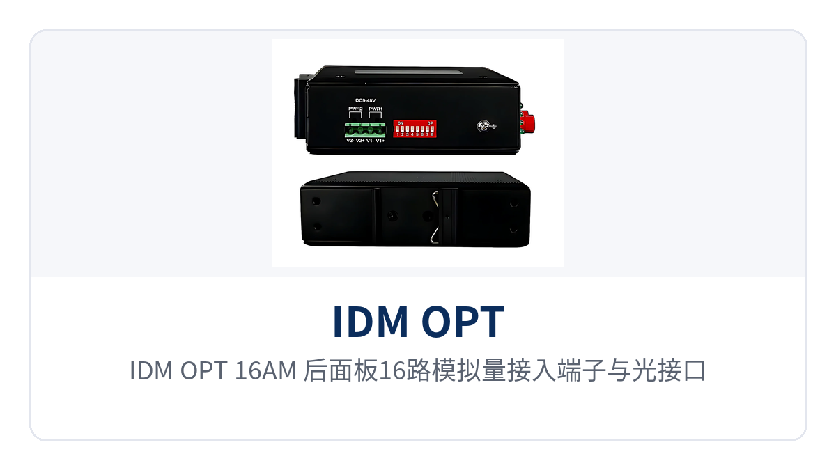
Figure 2: Rear panel layout of the IDM OPT-16AM with 16 analog access terminals and optical interfaces
Choose the installation position according to cabinet conditions: DIN-rail installation hooks the clip directly onto a standard rail, while wall-mounted installation fixes the unit to the backplate of the box using the mounting holes on both sides. At 0.75kg per unit, it takes no extra space in pole-side boxes or field cabinets. After power-on, check the power and optical link indicator LEDs first, then the channel indications; checking channel by channel saves more time than powering on the whole unit.
Typical application scenarios
What these three types of sites have in common is scattered measurement points, strong interference, and long-term unattended operation, while analog signals still need to be sent to a control room several kilometers away. Optical transmission replaces long cables in these cases, and the wiring at both ends is exactly the same as in a local cabinet, so the upgrade does not require changing the range settings of existing instruments and PLCs. For nodes that need to connect a fieldbus to an optical fiber link, a bridge converter can be used at both ends for interface matching, while the analog optical multiplexer and 4-20mA analog optical multiplexer covered in this article focus on long-distance transmission of current loop signals.
Industrial automation system integration
Variable-frequency drives, welding machines, and servo drives in the workshop are strong interference sources, and 4~20mA signals such as pressure, weighing, displacement, and flow can jump after running tens of meters along cable trays. Place one IDM OPT-16AM on the sensor side and one on the PLC side, and the 16 signals are converted to optical signals locally with only a single fiber in between, so acquisition values no longer fluctuate with drive start/stop—a typical practice for industrial automation analog remote acquisition.
For the integrator, the upgrade does not require replacing existing instruments and PLC modules: the terminals remain 4~20mA current loops with unchanged range and wiring, only the long cables are replaced with optical fiber, and delivery can proceed after channel-by-channel comparison with a standard signal source during commissioning, with in-cabinet cabling also simplified. If the project also involves Ethernet segment interconnection, an additional bridge converter can be configured to serve its own role alongside the optical multiplexer.
Electric power and energy remote monitoring
Current, voltage, oil temperature, and oil level signals at substations, hydropower stations, and photovoltaic booster stations must be sent from the switchyard to the main control room, and potential differences between the grounding grids at both ends and lightning induction are long-standing risks. Analog optical fiber relaying isolates the acquisition loop from primary equipment electrically, so lightning overvoltage no longer enters the capture card along the signal line.
Most such sites are unattended with tight cabinet space. The DIN-rail installation and 133×120×50mm enclosure of the IDM OPT-16AM fit into the free space of existing panels, and the -40℃~+85℃ wide temperature range and IP40 aluminum alloy enclosure suit indoor and outdoor box environments. When selecting, choose an optical multiplexer manufacturer with a proven on-site track record to reduce later maintenance disputes.
Rail transit and pipe gallery unattended operation
Fans, water pumps, fire dampers, and temperature, humidity, and water level sensors in tunnels and underground pipe galleries are scattered across several kilometers of section, and the control center needs continuous awareness of operating status. The 16 analog channels are backhauled over a single optical fiber, so signal cables no longer need to be laid separately for each measurement point within the section, significantly reducing civil works and cable tray workload.
Pipe galleries and tunnels are long-term unattended environments. The device is designed for industrial level 4 electromagnetic compatibility, with analog interfaces protected against 6kV differential and common mode per IEC61000-4-5; in humid and dusty environments, the IP40 enclosure and fanless heat dissipation provide protection, reducing the frequency of on-site inspection.
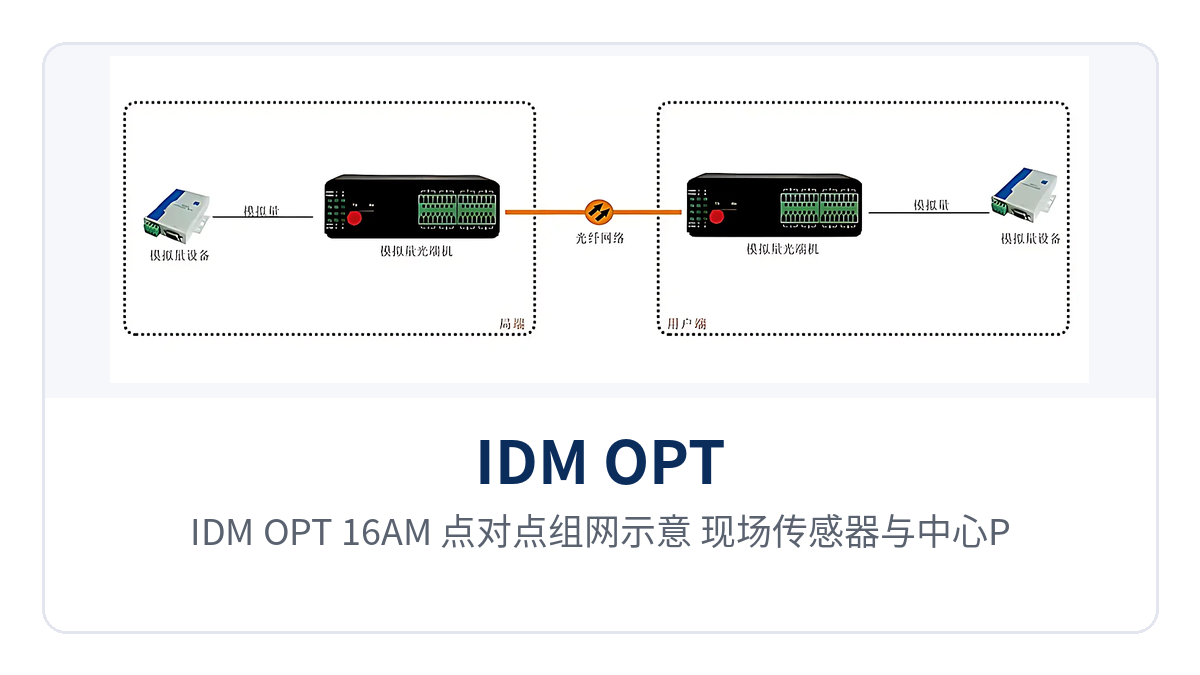
Figure 3: IDM OPT-16AM point-to-point networking schematic—single-fiber relaying of 16 analog channels between field sensors and a central PLC
How to select an analog optical multiplexer without rework?
Selection is settled by five items — channel count, signal type, transmission distance, power supply and installation method — so work out the configuration before ordering. If any of the five is left until the site, you may end up with too few channels, insufficient optical module distance or difficult power supply access, and rework usually costs more time than calculating ahead.
- Channel count: select the 16-channel model based on existing measurement points plus a margin of 2 to 4 channels, so later capacity expansion does not require another device.
- Signal type: current and voltage inputs can be combined freely on the same device; record the two types separately in statistics so that terminal arrangement does not cross over.
- Transmission distance: multi-mode is usable within 2 km, single-mode standard configuration for 20 km, and longer distances are confirmed with an optical module configuration supporting 120 km repeaterless transmission.
- Power supply: where only DC24V is available on site, choose the DC12-48V wide-range voltage input; only when the two power feeds come from different circuit breakers does redundancy truly take effect.
- Installation: choose DIN-rail installation inside cabinets, and wall-mounted installation for pole-side boxes and wall-mounted boxes; the 133×120×50mm enclosure requires clearance for heat dissipation.
Compared with continuing to use cables, the optical fiber solution puts its upfront investment into optical cable and splicing, and its long-term benefit into anti-interference and maintenance. In locations with strong interference, the cable solution often requires adding isolators, shielding layers and grounding rectification, and its points of failure are scattered along the entire line; an optical fiber link confines problems to the equipment at both ends and the optical cable itself, noticeably narrowing the troubleshooting scope, and capacity expansion does not require re-excavating trenches. Manufacturers focused on optical multiplexer development, such as Raytrans, can usually provide complete parameters for channel combinations and distance configurations in their product showcase, making item-by-item verification easy.
Conclusion
The analog optical multiplexer moves 420mA and 010V signals from long cables onto optical fiber, solving the four long-standing problems of interference, ground loops, lightning strikes and distance. IDM OPT-16AM uses a single fiber to relay 16 analog channels, with 20kHz sampling and 12-bit AD ensuring values are not distorted, and FPGA parallel read/write allowing all 16 channels to be restored synchronously.
For industrial automation, electric power and energy, and rail transit projects, a 0.75kg device supporting DIN-rail installation and redundant dual power supply can complete the upgrade without changing the existing wiring of instruments and PLCs, keeping on-site interference outside the optical fiber and confining maintenance work to the cabinets at both ends. Whether for a single 4-20mA analog optical multiplexer or a multi-channel combined solution, Raytrans provides the corresponding product showcase and selection support, making it easy for engineers to confirm each item according to on-site conditions.