
IDM OMP64 Integrated Service Optical Fiber Transmission Multiplexing Platform
A single optical fiber carries 64 telephone channels plus dual gigabit networks; 9 slots for on-demand card configuration
The IDM OMP64 optical multiplexer adopts a 19-inch 2U standard chassis; its total optical fiber transmission bandwidth is 2.5G, providing 2 independent 1000M Ethernet interfaces and 64 telephone subscriber channels; it provides 9 subscriber interface slots.
The IDM OMP64 Integrated Service Optical Fiber Transmission Multiplexing Platform is a 64-channel telephone 2.5G multiplexing optical multiplexer developed by Beijing Ruiguang Jiyuan Digital Technology Co., Ltd. (Raytrans), designed to carry 64 telephone voice channels and 2 independent gigabit Ethernet services simultaneously over a single optical fiber. The device uses a 19-inch 2U standard chassis, provides 9 groups of subscriber interface slots, and offers a total optical fiber transmission bandwidth of 2.5G.
As a 2.5G optical fiber multiplexing device, the IDM OMP64 consolidates voice, Ethernet, and leased-line data into the same optical fiber, replacing the separately deployed voice optical multiplexer and gigabit network optical multiplexer of the past with a single device. This multi-service optical multiplexer demonstrates the advantage of integration: the optical interfaces use pluggable SFP modules, single-mode with multi-mode optional, at a wavelength of 1310nm, making it easy to replace modules and spares according to line distance. As a professional optical multiplexer manufacturer, Raytrans can provide government private network optical fiber communication solutions and military emergency communications vehicle solutions.
Key Specifications at a Glance: 2.5G total optical fiber bandwidth · 64 telephone voice channels · dual gigabit Ethernet ports · -36dBm sensitivity · DC-48V/AC220V dual power supply · 19-inch 2U chassis with 9 groups of subscriber interface slots
What services can the 64-channel telephone 2.5G multiplexing optical multiplexer carry
As a typical multi-service optical multiplexer, the IDM OMP64 has two functional layers: the optical fiber side performs multiplexing and demultiplexing, while the service side provides voice, Ethernet, and expandable plug-in board interfaces. The table below lists the corresponding interface standards and functions by function item, so that on-site services can be matched item by item without consulting the entire document.
| Function | Description |
|---|---|
| 2.5G total optical fiber bandwidth | Optical interface is SFP, optical fiber rate 2.5G, wavelength 1310nm, single-mode with multi-mode optional; a single optical fiber carries 64 telephone voice channels and 2 independent gigabit Ethernet services simultaneously |
| 64 telephone voice channels | PCM30/31 format, audio range 300Hz~3400Hz, ITU G.711 A-law compression, loop current 25mA per channel; FXO and FXS support polarity reversal and caller ID |
| Dual gigabit Ethernet ports | 2 independent 1000M Ethernet interfaces, RJ-45, 10/100/1000Base-T adaptive, compliant with IEEE802.3, full/half duplex adaptive |
| 9 groups of subscriber interface slots | Can accommodate PCM service boards, serial port server cards, and Ethernet switching cards; services are expanded by slot combination |
| Alarms and network management | The panel provides a function control switch and alarm indication; network management supports online real-time configuration, query, and fault statistics management |
| Power and ringing current backup | Power cards and ringing current cards support dual backup and hot-swappable replacement; replacing a single card does not affect the operation of other services |
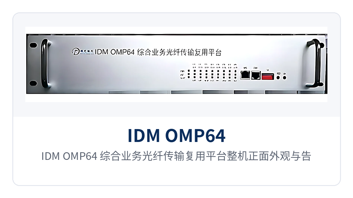
Figure 1: Front view and alarm indicator LEDs of the IDM OMP64 Integrated Service Optical Fiber Transmission Multiplexing Platform
Key Specifications
The technical specifications of the IDM OMP64 cover five parts: optical interfaces, Ethernet interfaces, FXO/FXS interfaces, power consumption, and environmental conditions. Values are subject to product documentation and factory testing. The parameter table lists specifications and applicable conditions item by item, and can be used directly to calculate the link budget and site power supply scheme.
| Item | Parameter/Specification | Description/Applicable Conditions |
|---|---|---|
| Chassis form | 19-inch 2U standard chassis | Rack installation, easy to secure in an equipment room cabinet |
| Subscriber interface slots | 9 groups | Boards combined according to service type and channel count |
| Optical fiber interface type | SFP | Pluggable modules, replaceable and spares according to line distance |
| Fiber mode | Single-mode (multi-mode optional) | Selected according to fiber core conditions and line distance |
| Optical fiber rate | 2.5G | Shared by 64 telephone channels and 2 gigabit Ethernet services |
| Wavelength | 1310nm | Typical wavelength for single-mode transmission |
| Transmit optical power | -2~-11dBm | Typical single-mode value; subject to actual measurement with an optical power meter |
| Receiver sensitivity | Better than -36dBm | Used to calculate the link loss budget |
| Voice capacity | 64 telephone voice channels | PCM30/31 format, ITU G.711 A-law |
| Ethernet interfaces | 2 independent 1000M, RJ-45 | 10/100/1000Base-T, IEEE802.3 compliant, full/half duplex adaptive |
| Audio range | 300Hz~3400Hz | Telephone voice channel bandwidth |
| Impedance | Three-element complex impedance 200Ω+560Ω//0.1μF | Telephone subscriber line interface standard |
| Compression | ITU G.711 A-law | 64Kbps PCM encoding |
| Loop current | 25mA per channel | Feeding capability of each voice channel |
| Power supply mode | DC-48V or AC220V | Selected according to site power supply format |
| Overall power consumption | ≤250W | Unit value with fully populated service boards |
| Operating temperature | 0℃~+40℃ | Equipment room and temperature-controlled cabinet environments |
| Humidity | 95% non-condensing | Upper limit of relative humidity |
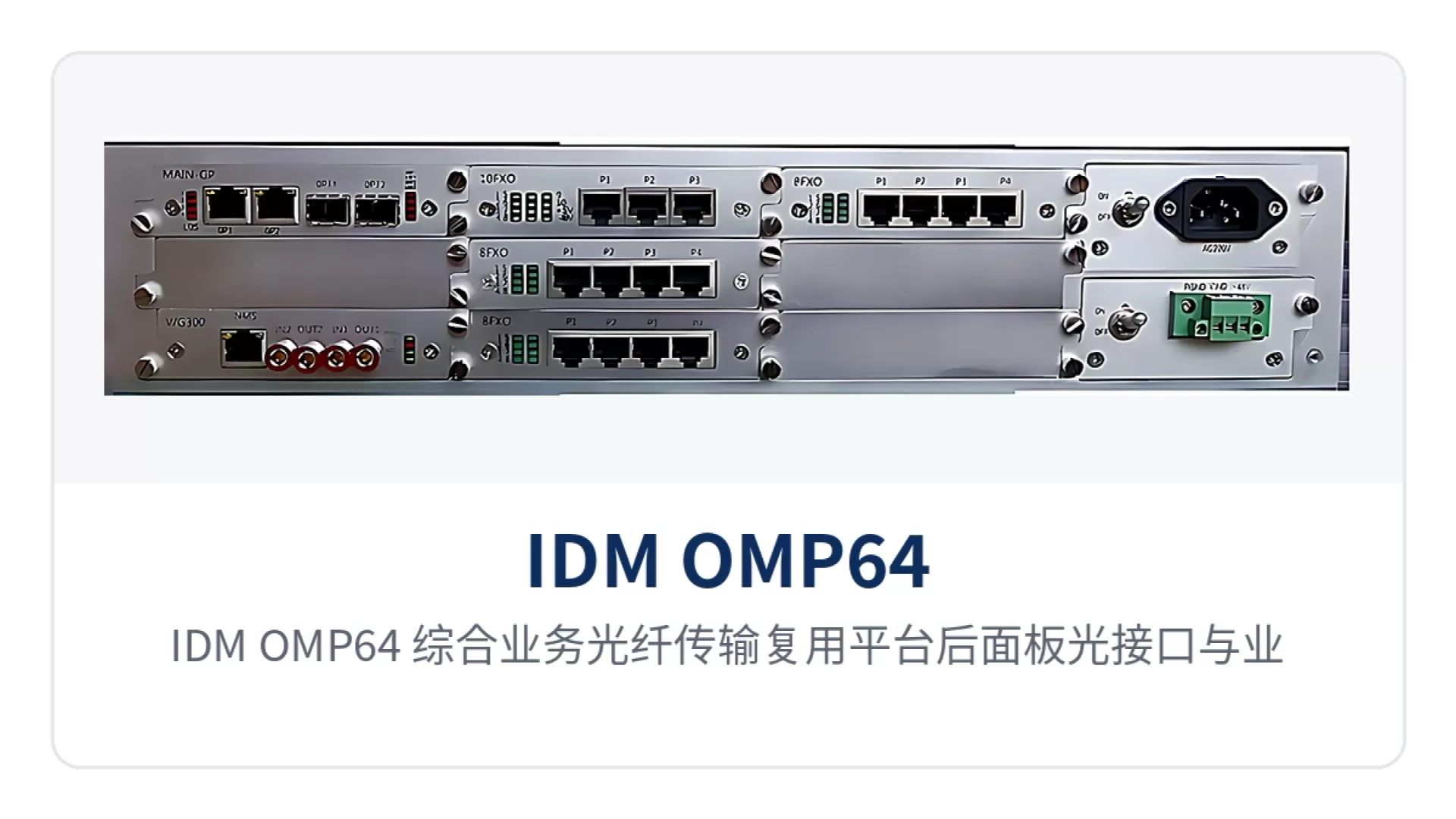
Figure 2: Rear panel optical interface and service interface layout of the IDM OMP64 Integrated Service Optical Fiber Transmission Multiplexing Platform
How does a single fiber at 2.5G simultaneously carry 64 telephone channels and 2 gigabit network services
The 2.5G optical path is divided internally into two types of channels: voice and data. The 64 telephone channels are packed into the E1 frame structure in PCM30/31 format; the E1 channel complies with the ITU-T G.703 standard, each voice channel occupies a 64Kbps time slot, and compression follows ITU G.711 A-law. The 2 gigabit Ethernet services each occupy an independent channel and negotiate rate according to IEEE802.3.
The two service types are multiplexed onto the same 2.5G optical path at the transmitter and output through the original interfaces after demultiplexing at the receiver. The key to this channelized design is that neither side changes the other's encoding or frame structure: the telephone side maintains standard channel-associated signaling and feeding, while the Ethernet side maintains standard Ethernet frames, and the devices on both sides interface according to their respective standards. For existing switching equipment, the IDM OMP64 acts as a transparent optical fiber extension; during cutover, only the voice channel mapping needs to be verified. As a gigabit network optical multiplexer and multi-service optical multiplexer for private network scenarios, the platform's ability to carry both voice and data over the same optical path is a common deployment form in government private network optical fiber communication solutions and military emergency communications vehicle solutions.
How to configure boards for the 9 groups of subscriber interface slots
The 9 slots determine the boundary of service expansion. The configuration approach is to first determine the main control card form, then add service cards according to voice channel and data requirements. Inserting different main control cards into the same chassis platform can derive different models; this IDM OMP64 is supplied with a 2.5G optical path, 2 independent gigabit Ethernet services, and 64 telephone voice channels.
The range of optional service boards is broad: voice, data, and aggregation board types can all be installed in the same chassis. On site, the board type, channel count, and number of occupied board positions are typically checked item by item in the following three categories, with voice first, then data and aggregation, to avoid missing boards or insufficient board positions that delay commissioning.
- Voice: FXS, FXO, EM 2/4-wire, hotline, ordinary magneto, 2100Hz magneto; board type selected according to exchange side or user side;
- Data: V.24/RS422/RS485, V.35, bridge, HIFI, GSM/CDMA, used for telecontrol, protection, or wireless backhaul services;
- Aggregation: 3UMPconv optical port expansion card, 30-channel serial port server board in the P4 slot, 8-group 100M Ethernet switching card in the P6 slot (occupies 2 board positions), 4-group Ethernet switching card in P2 and P6 (occupies 1 board position).
When configuring boards, first confirm with the optical multiplexer manufacturer the number of board positions occupied by each service board and the slot mapping, to avoid the situation where slots are sufficient but board positions are not. Once board positions and service volume are determined, calculate the optical fiber side bandwidth and the peer configuration, and equip both ends at once. Raytrans provides a complete board type list and slot cross-reference in its product showcase, which can be checked directly during selection.
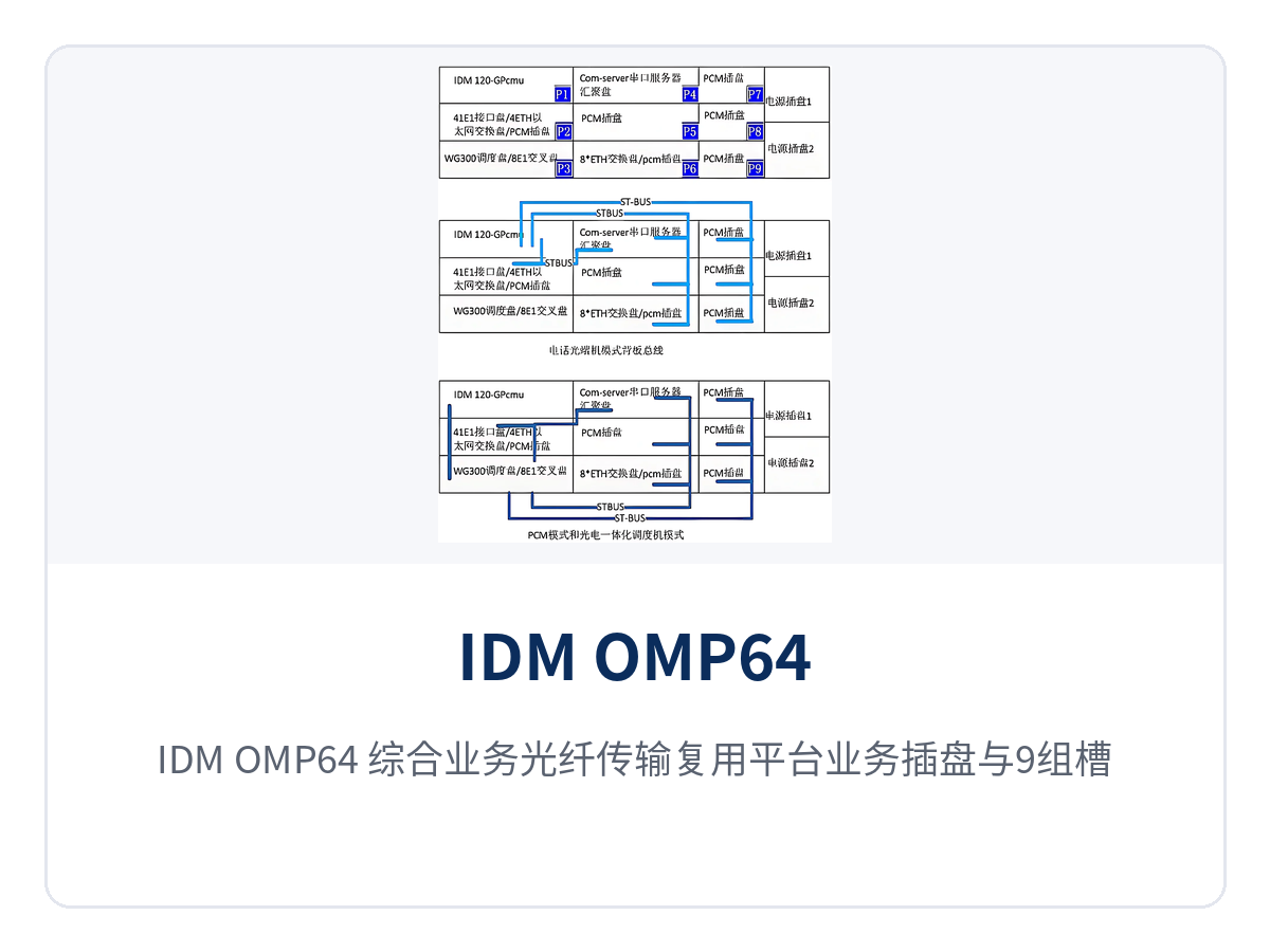
Figure 3: Close-up of service boards and 9 slots of the IDM OMP64 Integrated Service Optical Fiber Transmission Multiplexing Platform
Stable transmission over weak optical links: how to use the -36dBm sensitivity
Receiver sensitivity better than -36dBm is the source of margin for the IDM OMP64 over long-distance and weak optical links. Based on transmit optical power of -2~-11dBm and receiver sensitivity of -36dBm, the optical power budget from one end to the other is approximately 25dB, which can cover losses caused by optical cable splices, patch cords, optical splitting components, and fiber aging.
When calculating, first take the lower limit of the local transmit optical power, -11dBm, then subtract the peer receiver sensitivity of -36dBm to obtain the available loss budget; then accumulate the per-kilometer optical cable loss, the number of splice points, and the number of patch cords item by item, and reserve maintenance margin according to engineering practice. The actual transmission distance depends on the selected SFP module grade and line conditions; measuring the received optical power with an optical power meter before commissioning is more reliable. This margin design enables the telephone optical multiplexer to maintain stable output of voice and data services over long-distance weak optical links.
How to choose between DC-48V and AC220V power supply
The power supply mode is selected between DC-48V and AC220V according to the site power supply format: communications equipment rooms and power supply stations mostly use -48V DC communications power, while station buildings and office buildings mostly use 220V AC mains power. Overall power consumption is ≤250W; during selection, check the air switch and wire gauge against the on-site power supply capacity, and include device grounding in the construction plan.
Power-on steps are performed in sequence, with each step completed and verified before proceeding to the next, so that faults can be located to a single stage and repeated disassembly is reduced. Most common on-site issues of no optical path and no voice are found in the first three steps, without waiting for full commissioning.
- Verify that the voltage marked on the device matches the equipment room power supply format, and confirm the terminal wiring is correct;
- Check that the protective grounding and power supply terminals are securely crimped, to avoid loosening under load;
- After power-on, observe the power and alarm indicator LEDs, and confirm normal received optical power at the optical port;
- Verify the telephone voice channels and the two Ethernet services one by one, then perform a long-duration call test.
Typical Application Scenarios
The IDM OMP64 is mainly deployed point-to-point: one device at each end, interconnected by a single optical fiber, with the telephone and Ethernet services at the site side restored at the central equipment room and connected to existing switching equipment. The following three industries are common deployments for this dual gigabit telephone optical multiplexer; for capacity expansion, only additional service boards are needed, without laying new optical cables.
Electric power private network: dispatch telephone and in-station data backhaul over a single optical fiber
Substations, power supply stations, and dispatch centers usually need to transmit dispatch telephone, telecontrol data, and in-station office network simultaneously. The IDM OMP64 is installed at each site, combining 64 telephone voice channels and 2 gigabit Ethernet services onto a single 2.5G optical path, replacing the past practice of separately deploying telephone optical multiplexers and network optical multiplexers, while reducing both the number of devices and the cabling workload in the equipment room.
The telephone side is connected in PCM30/31, G.711 A-law, with a loop current of 25mA per channel, and can be directly connected to dispatching switching equipment; the data side uses 2 gigabit Ethernet services to independently carry in-station surveillance and office services. DC-48V power supply matches existing communications power, and the dual backup and hot-swappable design of power cards and ringing current cards facilitates replacement of faulty cards without interrupting services.
Rail transit communication: telephone and gigabit data transmission over the same cable between stations and sections
Between stations, depots, and line sections, train dispatching telephone, PA voice, and monitoring data need to be transmitted, while sites are distributed and optical fiber resources are scarce. The IDM OMP64 packs 64 telephone channels and 2 gigabit Ethernet services into a single optical fiber, reducing the fiber core requirement of section optical cables, benefiting both new lines and existing line upgrades.
The 9 slots allow different stations to configure boards differently according to service volume: stations with heavy traffic get more voice cards, while sites with more monitoring points add serial port server cards or Ethernet switching cards. The device operates at 0℃~+40℃ and 95% non-condensing humidity, and can run stably when deployed in a temperature-controlled communications equipment room.
Military and government private networks: remote stations with selectable dual power supply and visible alarms
Remote stations of the military, government and political-legal systems are often unattended, with limited power supply and maintenance conditions—exactly the considerations that the military emergency communications vehicle solution and the government private network optical fiber communication solution must address. IDM OMP64 supports optional DC-48V and AC220V power supply, adapting to both equipment room direct current power and site mains power; the front panel function control switch and alarm indication let duty personnel judge the operating status without opening the enclosure.
The network management system enables online real-time configuration, query and fault statistics management of the device, so the central equipment room can remotely monitor the services and alarms of remote stations and reduce inspection trips. The 19-inch 2U chassis fits easily into a standard cabinet, and its 9 groups of slots allow voice channel and data configuration to be adjusted according to mission needs.
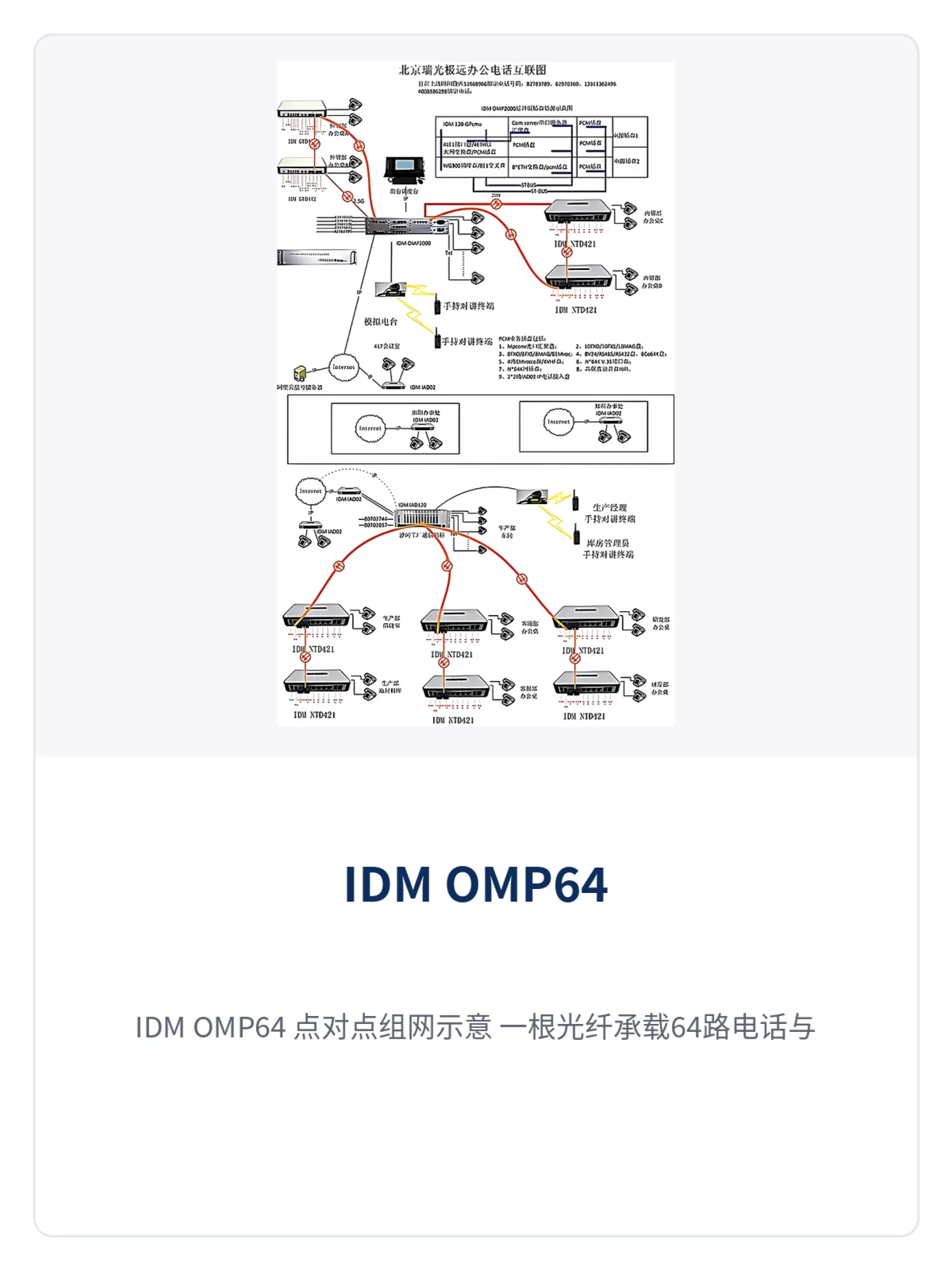
Figure 4: IDM OMP64 point-to-point networking schematic—a single optical fiber carries 64 telephone channels and dual gigabit Ethernet
Conclusion
As a 64-channel telephone 2.5G multiplexing optical multiplexer, IDM OMP64 packs 64 telephone voice channels, 2 independent gigabit Ethernet ports and scalable service boards into a 19-inch 2U chassis, with SFP modules for the optical ports, receiver sensitivity better than -36dBm, and DC-48V or AC220V power supply options. For scenarios such as electric power private networks, rail transit communication and military and government private networks with distributed sites and limited optical fiber, a single device completes voice and data backhaul.
Selection follows a three-step closed loop: first count the on-site voice channels and Ethernet ports to determine the main control card and service board configuration; then calculate the optical cable loss budget to confirm the SFP module grade and line margin; finally check the site power supply format and cabinet space. Once these three steps are settled, the final configuration and quotation can be confirmed with the manufacturer.
—— Master draft (TYPE + frontmatter + body) ——


