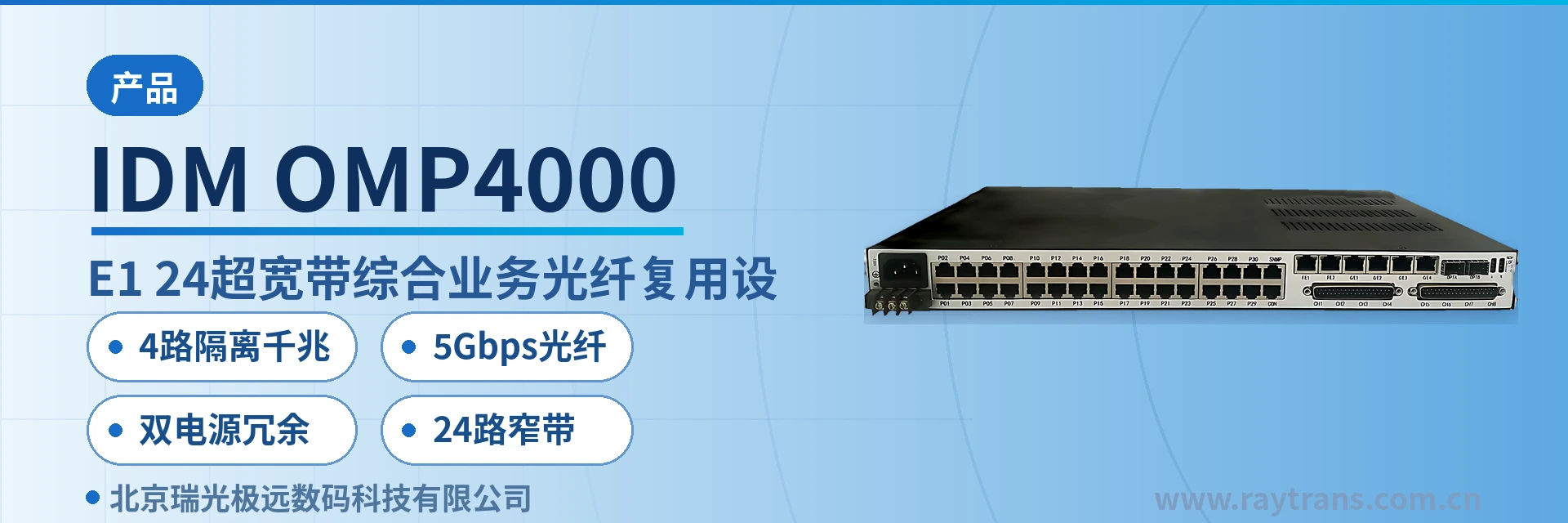
IDM OMP4000-8E1-24 Ultra-Broadband Integrated Service Optical Multiplexing Equipment
4-channel isolated gigabit
The IDM OMP4000-8E1-24 physically isolated gigabit network optical multiplexer utilizes 5G optical fiber transmission bandwidth (G.703 standard) and adopts the PCM30/31 format. It provides dual-fiber mutual backup, 24-channel 64K narrowband subscriber access + 4E1 + 4 physically isolated line-rate gigabit Ethernet interfaces, and dual 2.5G optical fiber parallel transmission. Meanwhile, the IDM OMP4000-8E1-24 physically isolated gigabit network optical multiplexer is simple to install and can meet the requirements of various application environments.
The IDM OMP4000-8E1-24 24-channel narrowband service optical multiplexer is an ultra-broadband integrated service optical multiplexing equipment developed by Beijing Ruiguang Jiyuan Digital Technology Co., Ltd. (Raytrans). As a PDH optical transmission device with excellent performance, it is used at private network access points to converge narrowband voice, E1 leased lines and physically isolated gigabit Ethernet into optical fiber transmission in one pass, meeting the product showcase requirements of unified multi-service access.
The device adopts the PCM30/31 format, and its E1 channels comply with the ITU-T G.703 standard. The line side is equipped with 2 SFP optical ports and dual 2.5G optical fibers for parallel transmission, with an overall optical fiber bandwidth of 5Gbps. As a professional optical multiplexing equipment and integrated service access device, it provides 24-channel 64K narrowband access, 4 E1 channels and 4 physically isolated gigabit network ports on the user side. A single PCM equipment at one site completes the aggregation and backhaul of three types of services, making it widely applicable to scenarios such as government private network optical fiber communication solutions and military emergency communications vehicle solutions, demonstrating the technical strength of Raytrans as an optical multiplexer manufacturer.
Key specifications at a glance: dual 2.5G SFP optical ports · 5Gbps optical fiber bandwidth · 24-channel 64K narrowband access · 4-channel E1 transparent transmission · 4-channel physically isolated gigabit network · dual power supply DC-48V/AC220V · overall power consumption ≤100W
What kind of device is the 24-channel narrowband service optical multiplexer
The 24-channel narrowband service optical multiplexer refers to a PCM equipment that simultaneously provides 24-channel 64K narrowband service access and an optical fiber uplink channel within a single device. The narrowband side is framed according to the PCM30/31 frame structure and then transmitted transparently, and the peer end demultiplexes it back to the original telephone, audio or data interfaces.
The IDM OMP4000-8E1-24 uses a 19-inch 1U chassis, in which subscriber interface cards are configured by service type. Available card types include FXO/FXS, 2/4-wire E&M, RS232/RS422/RS485, codirectional 64K, magneto, high-fidelity and X.50. Interface cards are combined according to site services; when site services increase, additional or replacement cards suffice, without replacing the complete unit.
The optical ports are pluggable SFP structures, with single-mode as the standard configuration and multi-mode modules optional for short-distance cabling. The wavelength is 1310nm/1550nm, the transmit optical power is -1~-3dBm, and the receiver sensitivity is better than -24dBm. The panel provides a function control switch and alarm indication, so O&M personnel can determine link and service status on site. As a mature product of a professional optical multiplexer manufacturer, Raytrans has accumulated rich product showcase and engineering application experience in this series, and the device can be widely adapted to scenarios such as government private network optical fiber communication solutions and military emergency communications vehicle solutions.
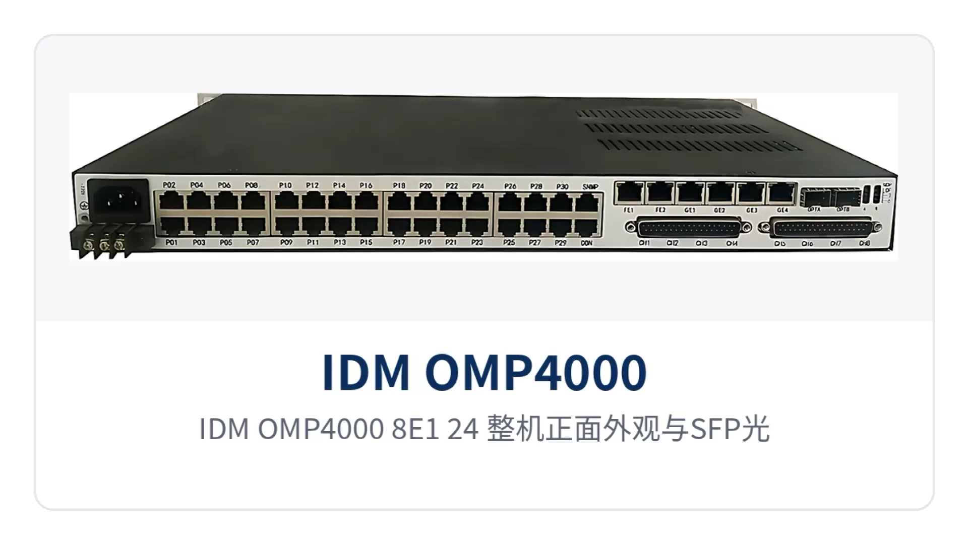
Figure 1: Front view of the IDM OMP4000-8E1-24 unit with close-ups of the SFP optical ports and service alarm indicator LEDs
What services can one device carry: an overview of functions and carrying capacity
The IDM OMP4000-8E1-24 completes narrowband service access, E1 transparent transmission and isolated gigabit Ethernet aggregation within a single 1U device, with functions covering four categories: transmission, access, protection and network management. The function items in the table correspond one-to-one with on-site services; during selection, simply check each row according to site services to determine the configuration.
| Function | Description |
|---|---|
| Dual 2.5G optical fiber transmission | The line side is equipped with 2 SFP optical ports and dual 2.5G optical fibers for parallel transmission, with an overall optical fiber bandwidth of 5Gbps |
| 1+1 protection for optical ports | The two optical ports can form dual-fiber mutual backup; when one optical path is abnormal, services are switched to the other optical path |
| 24-channel 64K narrowband access | Provides 24-channel 64K narrowband subscriber interfaces, adopts the PCM30/31 format, and uses A-law encoding per ITU G.711 |
| 4-channel E1 transparent transmission | 4 E1 channels are transmitted in transparent transmission mode, with a bit rate of 2048Kbps and HDB3 line code, compliant with ITU-T G.703 |
| 4-channel physically isolated gigabit network | Provides 4 physically isolated line-rate gigabit Ethernet ports, RJ45 interfaces, 10M/100M/1000M adaptive |
| Multiple types of subscriber interface cards | Configurable with FXO/FXS, 2/4-wire E&M, RS232/RS422/RS485, codirectional 64K, magneto, high-fidelity and X.50 cards |
| SNMP network management | Provides a standard SNMP network management interface and can be incorporated into an existing network management system (NMS) for unified monitoring and configuration |
| Alarm indication | The panel is provided with a function control switch and alarm indication for on-site locating of link and service abnormalities |
| Dual power supply | Supports DC-48V and AC220V dual power supply access, suitable for mains-powered equipment rooms and DC power sites |
Key Specifications
The parameters are listed in five parts: optical interface, E1 interface, Ethernet interface, audio interface and power supply environment, with values taken from the original product documentation. During engineering calculation, take values item by item from the table; the optical power budget and site power supply capacity are both based on the specifications in the table. Before selection, align these five categories of parameters with site conditions item by item, then determine the optical module grade and power supply configuration, which can reduce second-round order changes.
| Item | Parameter/Specification | Description/Applicable Conditions |
|---|---|---|
| Optical interface type | SFP | Pluggable module, selected according to line distance and optical fiber type |
| Fiber mode | Single-mode (multi-mode optional) | Single-mode for medium- and long-distance links, multi-mode for short-distance cabling |
| Optical fiber rate | 5Gbps | Overall bandwidth of dual 2.5G optical fibers in parallel transmission |
| Wavelength | 1310nm/1550nm | Determined by the selected optical module |
| Transmit optical power | -1~-3dBm | Typical transmit specification of the optical module |
| Receiver sensitivity | Better than -24dBm | Typical specification on the receive side; link margin is calculated accordingly |
| E1 bit rate | 2048Kbps | Rate of a single E1 channel |
| E1 line code | HDB3 | Compliant with ITU-T G.703 |
| E1 impedance | 75 Ω/120 Ω | Selected according to the peer device interface |
| E1 frame structure | PCM30/31 | Transparent transmission mode, without changing the original frame structure |
| Ethernet interface | RJ45, 10M/100M/1000M | Supports IEEE802.3, full/half duplex/adaptive |
| Voice frequency band | 300Hz~3400Hz | Voice frequency band requirement for FXO/FXS |
| Voice impedance | Three-element complex impedance 200Ω+560Ω//0.1μF | FXO/FXS interface parameter |
| Voice compression | A-law per ITU G.711 | 64Kbps PCM encoding method |
| Loop current | 25mA per channel | Feeding capability of each voice channel |
| Power supply mode | DC-48V / AC220V / dual power supply | Connected according to site power supply format; two feeds can supply power simultaneously |
| Overall power consumption | ≤100W | Overall power consumption specification |
| Operating temperature | 0℃~40℃ | Equipment room and temperature-controlled cabinet environments |
| Relative humidity | ≤90% (non-condensing) | Indoor installation conditions |
How are the 4 physically isolated gigabit network ports connected
Physical isolation means that the 4 gigabit Ethernet ports each occupy an independent channel and independent forwarding within the device, and the data plane and bandwidth are not shared between ports. A traffic burst on one port will not consume the forwarding capability of other ports, and there is no mutual influence between services caused by shared buffers.
The Ethernet interfaces are RJ45, with a transmission rate of 10M/100M/1000M adaptive, compliant with the IEEE802.3 standard, and the operating mode supports full/half duplex/adaptive. Each channel is forwarded at interface line rate and transmitted in parallel with narrowband services and E1 channels over the same optical fiber, without contending with one another.
On site, services are allocated by security domain, one security domain per channel, and no inter-port access control is needed after wiring. The common division of the four isolated ports is adjusted according to site service volume, generally referring to the following combinations; when ports are tight, prioritize the two service types of video and dispatch:
- The video surveillance network exclusively occupies one channel, with camera streams separated from other services;
- The office network and the production management network each occupy one channel, and the two networks are invisible to each other;
- Dispatch data or telecontrol services occupy one channel, separated from video and office services;
- Spare ports are reserved in the cabinet for direct access of new services later.
Isolation is completed at the hardware channel level without relying on VLAN partitioning of switches, and servicing one group of ports does not affect the operation of other services. Troubleshooting of port abnormalities is limited to that service itself and does not involve the overall device configuration. This is particularly suited to the requirement of electric power, rail transit and military/police private networks to carry multiple independent networks simultaneously, and is precisely one of the reasons why Raytrans integrated service access devices are widely recognized in government private network optical fiber communication solutions.
How do dual 2.5G optical fibers and dual power supplies ensure service continuity
The two SFP optical ports on the line side can form 1+1 protection for optical ports; the dual-fiber mutual backup connection allows services to be switched to the standby optical path when the primary optical path is abnormal. Switching at the optical path layer is transparent to the service side; narrowband voice channels and gigabit Ethernet need no reconfiguration, and no manual switchover is required at the site side.
On the power supply side, DC-48V and AC220V dual power supply redundancy access is supported; the equipment room DC communications power supply and the site AC mains power can be connected simultaneously, and if one feed loses power, the other continues to supply power. The overall power consumption is ≤100W, and the existing power supply capacity at the site can usually bear it directly, without separate capacity expansion for the device.
E1 channels adopt transparent transmission mode, with a bit rate of 2048Kbps, HDB3 line code, and selectable 75 Ω/120 Ω impedance; they can interconnect with existing PCM equipment and also deliver E1 services to the peer end as-is. Narrowband services, E1 and the isolated gigabit network belong to different channels, and cutover of one service type does not affect the other two. This combined form of PCM equipment and optical multiplexing equipment gives Raytrans optical transmission equipment a reliable deployment foundation in demanding occasions such as military emergency communications vehicle solutions that require strict continuity.
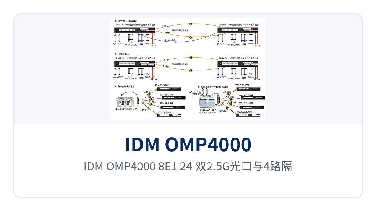
Figure 2: Point-to-point networking topology of the IDM OMP4000-8E1-24 with dual 2.5G optical ports, 4 isolated gigabit network ports and 24-channel narrowband services
Typical application scenarios
The IDM OMP4000-8E1-24 is mainly deployed in point-to-point mode: one device is placed at the service-side site and one at the central equipment room, with the two ends directly connected by optical fiber. The following three industries are common landing points for this 5Gbps optical multiplexing equipment, and also cover the typical application profiles in the PDH product showcase.
Electric power distribution network and substation communications: isolated gigabit network and dispatch narrowband services backhauled over the same cable
Substations, distribution stations and renewable energy booster stations simultaneously run three types of services: dispatch telephone, telecontrol data and video surveillance. Sites are mostly unattended, and both equipment room space and the number of fiber cores are limited. The IDM OMP4000-8E1-24 aggregates 24-channel 64K narrowband services, 4 E1 channels and 4 physically isolated gigabit network ports into the same 1U device, so there is no need to equip a separate optical multiplexer for each service type in the station; one integrated service access device completes multi-service aggregation.
Dispatch telephones and hotlines connect to FXO/FXS cards, telecontrol and protection information run over E1 channels, and video surveillance, office and production management networks each occupy one isolated gigabit port. Dual power supplies connect to the station DC communications power supply and AC mains power, and the 0℃~40℃ operating temperature suits temperature-controlled communications equipment rooms; after rack mounting, services can be commissioned by connecting wiring according to the installation drawing.
Rail transit line communications: dual 2.5G parallel transmission and dual power supplies support uninterrupted section services
Sites along railways, metros and expressways are spaced several kilometers apart, and inter-station services include train dispatch telephone, PA voice, monitoring data and office networks, with distributed access points and limited equipment room conditions. The IDM OMP4000-8E1-24 is cascaded level by level according to site distribution; each station accesses services locally and backhauls them to the central equipment room over trunk optical fibers, serving as optical multiplexing equipment for the aggregation and backhaul of multi-service channels along the line.
Dual 2.5G optical fibers in parallel transmission keep 24 narrowband channels and 4 isolated gigabit network ports online simultaneously; video surveillance exclusively occupies one isolated port, dispatch telephone and data use their respective interfaces, and they do not interfere with one another during link servicing. The combination of dual power supplies and dual-fiber mutual backup allows line services to continue running during servicing of a single optical path or a single power feed.
Military and government private networks: multi-service access points for rapid on-site commissioning
Field command posts, temporary training sites, and emergency communications sites usually have no existing transmission resources, so telephone, data, and network channels must be established within a short time. The IDM OMP4000-8E1-24 is a 19-inch 1U chassis that is easy to transport and rack-mount. Once the devices at both ends are provisioned as a pair, narrowband, E1, and physically isolated gigabit network services can run simultaneously over a pair of optical fibers. This meets the rapid deployment requirements of military emergency communications vehicle solutions and can also serve as a remote access node in government private network optical fiber communication solutions.
The 4 physically isolated gigabit networks let the command network, video backhaul network, and office network each use an independent channel, separating classified and non-classified services at the hardware level. The SNMP network management interface allows the central equipment room to remotely check the status of remote-end devices, reducing travel for field duty and inspection. Alarm indications and function control switches let on-site personnel make basic judgments even without instruments.
Conclusion
As a 24-channel narrowband service optical multiplexer that packs broadband and narrowband services into a single 1U chassis, the IDM OMP4000-8E1-24 provides 5Gbps optical fiber bandwidth through dual 2.5G optical fiber transmission in parallel, carrying 24-channel 64K narrowband access, 4 E1 channels, and 4 physically isolated gigabit networks, with dual power supply and overall power consumption ≤100W. Raytrans has long been engaged in the field of optical transmission equipment and PCM equipment, and this model is one of the representative models in its optical multiplexer manufacturer product line for multi-service access.
For scenarios such as electric power distribution networks, rail transit lines, and military and government private networks, where sites are distributed and optical fiber and equipment room space are limited, a single device can complete same-cable backhaul of narrowband services and isolated gigabit networks. During selection, first count the number of narrowband channels, E1 channels, and Ethernet security domains at the site, then check the optical module grade and the site power supply format to determine the configuration at both ends.