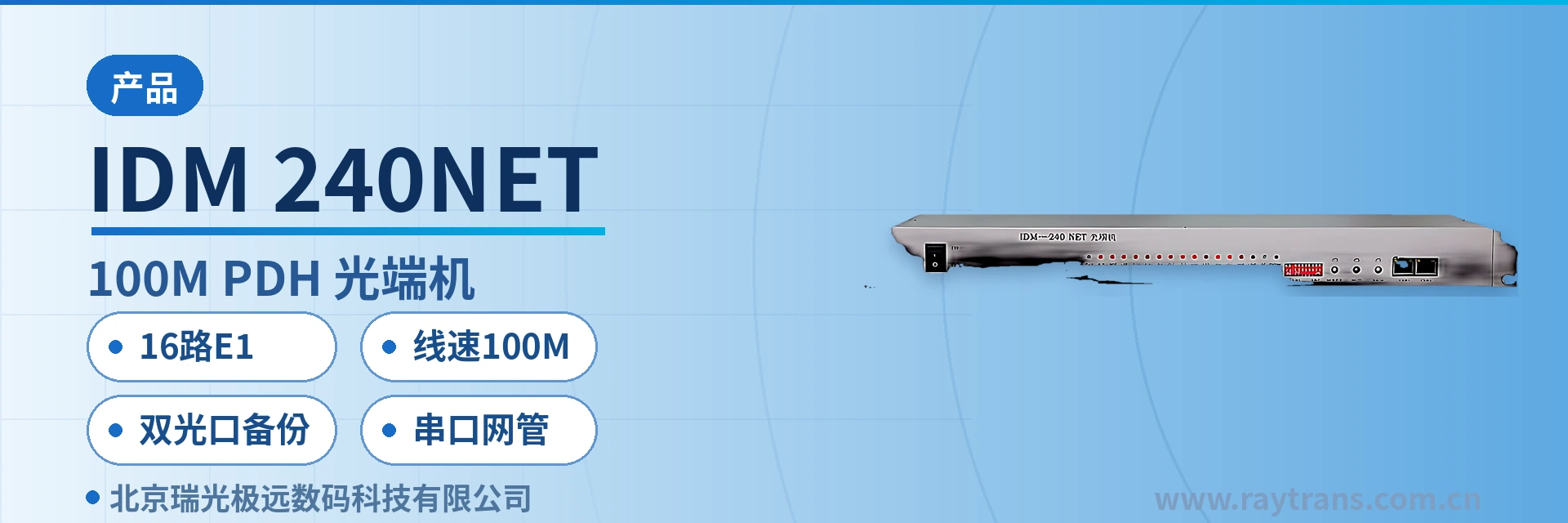
IDM-240NET 8E1+100M PDH Optical Multiplexer
Single board multiplexes E1 and wire-speed Ethernet, saving one switch; dual optical port protection; serial port network management
The IDM-240NET optical multiplexer is a point-to-point optical transmission device developed with large-scale integrated circuits. On a single board, it implements hybrid multiplexing of up to 8 E1 services, optical transmission of 4 shared 100M wire-speed Ethernet data channels, and 1 RS232 interface, and supports dual optical port mutual backup and serial port network management.
The IDM-240NET 8E1+100M PDH optical multiplexer is an 8-channel E1 plus Fast Ethernet hybrid multiplexing optical multiplexer (an E1 and Ethernet hybrid multiplexing device), developed by Beijing Ruiguang Jiyuan Digital Technology Co., Ltd. (Raytrans) using large-scale integrated circuits. It is used to simultaneously transmit 8 E1 services and 2 groups of wire-speed 100M Ethernet services with VLAN partitioning over a point-to-point optical fiber link. It is a typical E1 and Ethernet hybrid multiplexing device and a representative model in the PDH product line for multi-service access.
The device performs service multiplexing on a single board: at one end it multiplexes the site's existing E1 channels and Ethernet services into the optical fiber, and at the other end it restores them unchanged to standard interface outputs, so a single optical fiber link carries all backhaul. This 8E1 plus Fast Ethernet hybrid multiplexing optical multiplexer is deployed as a pair at both ends, and rack positions, power supplies, and optical module spare parts are all counted as one device. The site side no longer needs a separate transmission device for each service type, and when used as a multi-service optical multiplexer it significantly simplifies site product showcase and spare parts management.
Key Specifications at a Glance: 8 E1 channels (ITU-T G.703) · 2 groups of wire-speed 100M Ethernet with VLAN partitioning · dual optical port backup · 1 RS232 serial port network management channel · single-board point-to-point deployment · expandable to 16 E1 channels within the same series
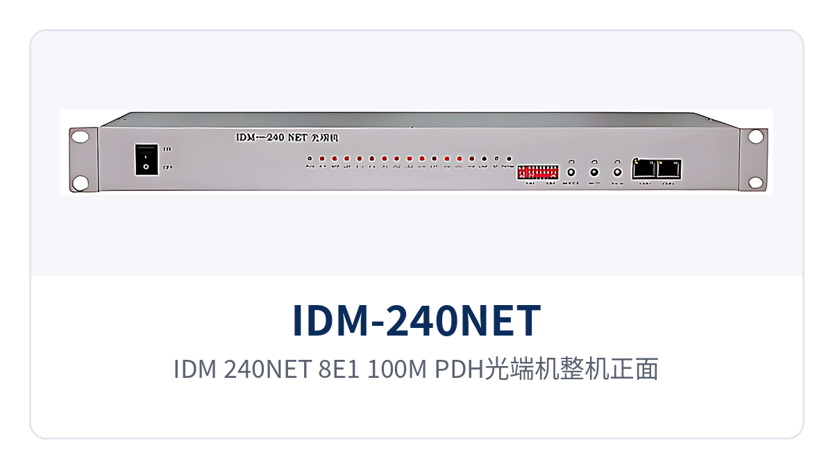
Figure 1: Front appearance of the IDM-240NET 8E1+100M PDH optical multiplexer, single-board enclosure and panel operation and alarm indicator LEDs
What kind of device is the 8-channel E1 plus Fast Ethernet hybrid multiplexing optical multiplexer?
Hybrid multiplexing means that narrowband E1 circuits and broadband Ethernet services each occupy independent channels within the same device and are then multiplexed onto the same optical path for transmission, so the two service types do not take bandwidth from each other. On the E1 side, only multiplexing and demultiplexing are performed, without parsing or rewriting the original frame structure, so the existing PCM equipment, digital trunk equipment, and dispatch automation devices at the opposite end continue to work with their original parameters. This channel isolation design at the product showcase level is a typical feature of PDH optical multiplexers in private network access scenarios.
The Ethernet side transmits and receives according to the IEEE802.3 standard, and the 2 groups of interfaces support VLAN partitioning, so services of different security levels can be separated at the ports, and the site side no longer needs an external switch for isolation. Bringing E1 leased lines and VLAN-capable Ethernet into a single board is exactly the practical value of the 8-channel E1 plus Fast Ethernet hybrid multiplexing optical multiplexer on old lines with limited fiber cores, and it also reflects the integration approach of multi-service optical multiplexers at the access layer.
How are the 8 E1 services transparently transmitted?
E1 channels transmit and receive at a bit rate of 2.048Mbps according to the ITU-T G.703 standard. After the 8 E1 channels enter the device, only multiplexing is performed, and the time slot content is delivered unchanged to the opposite end. During service provisioning, simply connect the existing E1 cables to the corresponding interfaces; the opposite-end device does not need configuration changes or new time slot mapping, and the cutover window can be kept within single-channel verification. The advantage of this type of E1 and Ethernet hybrid multiplexing device during provisioning lies precisely in transparent transmission that causes zero disturbance to existing services.
The direct benefit of transparent transmission is a small amount of modification work. The trunk channels of dispatch automation, relay protection, signaling systems, and SPC switching all operate with their original parameters, and there is no protocol conversion between the two ends. During on-site troubleshooting, it is only necessary to compare the receive/transmit directions and alarm states, without re-checking each service one by one.
How are the 2 groups of 100M Ethernet ports partitioned into VLANs?
The 2 groups of 100M Ethernet interfaces forward at wire speed. When connected to an existing switch, the rate and duplex mode are negotiated according to the IEEE802.3 standard, with no configuration change needed on the device side. The ports support VLAN partitioning, so services such as surveillance, office, and production control are assigned to different VLANs by security domain, and the network boundary is partitioned inside the device.
The result of this approach is a reduced number of devices. In the past, a site needed a media converter for each network plus an isolation switch; now one optical multiplexer and one optical fiber suffice, rack positions and wiring are simplified accordingly, and port maintenance affects only the services carried by that VLAN.
How do dual optical port mutual backup and serial port network management work together?
Two optical ports are configured on the line side, one active and one standby. When the active optical fiber is interrupted or the received optical power is insufficient, services continue through the standby optical port, and the service interfaces and terminal configurations at both ends remain unchanged. For dual optical port backup to be meaningful, the two optical cables should follow different routes; if they run in the same trench or cable, a single external break will interrupt both links at once, and this must be decided during design and construction.
One RS232 interface provides a serial port network management channel, so on-duty personnel can check device and link status without visiting the site, incorporating optical port switching and alarm records into routine inspection. Link redundancy protects services first, and serial port network management then identifies whether the problem lies in the optical fiber, the optical module, or the service interface, shortening the fault handling path.
What services can one device carry?
The functions of the IDM-240NET revolve around four main lines: E1 transparent transmission, isolated Ethernet, optical link protection, and remote O&M. The role and applicable conditions of each capability are listed in the table below. During selection, check the interface quantity and configuration mode line by line against the site service list, so as to avoid discovering port mismatches only after the complete unit arrives. As a typical PDH optical multiplexer product, its functional configuration also reflects the product showcase approach of optical multiplexer manufacturers in the private network access field.
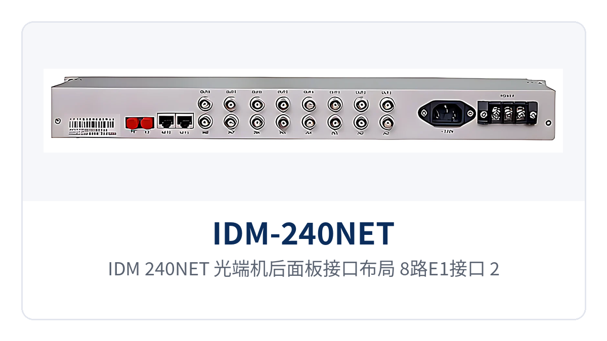
Figure 2: Rear panel interface layout of the IDM-240NET optical multiplexer, positions of 8 E1 interfaces, 2 groups of 100M Ethernet ports, RS232 serial port, and dual optical ports
| Function | Description |
|---|---|
| 8-channel E1 hybrid multiplexing | The single board provides 8 E1 channels, transmitting and receiving at 2.048Mbps according to the ITU-T G.703 standard; multiple E1 channels are multiplexed and transmitted over one optical path |
| Wire-speed 100M Ethernet | Provides 2 groups of 100M Ethernet interfaces, forwarding at port wire speed and carried in parallel with E1 services over the same optical path |
| VLAN partitioning | Ethernet ports support VLAN partitioning, so services of different security domains are separated at the ports, and private network service isolation requires no external switch |
| Dual optical port backup | The two optical ports on the line side are active and standby; when the active optical fiber fails, services continue through the standby optical port with terminal configurations unchanged |
| Serial port network management | Provides 1 RS232 interface for serial port network management, allowing device and link status to be checked from the central side |
| Single-board point-to-point form | All service multiplexing is implemented on a single board, deployed as a pair at both ends, with site-side rack positions and wiring counted as one device |
| Alarm indication | Panel indicator LEDs reflect device and link status; together with serial port network management, they distinguish optical path, module, and service interface anomalies |
| Same-series expansion | Single boards in the same series can be expanded to 16 E1 channels; when site capacity increases, a higher-capacity model is used with unchanged service scope and configuration mode |
How to choose between core specifications and same-series models
The specifications are listed in four parts: E1 interfaces, Ethernet interfaces, optical ports, and management mode, with values taken from the original product documentation. For electrical and environmental specifications not given in the documentation, the table notes that the technical documentation supplied with the unit prevails; confirm with the manufacturer before link calculation and power capacity calculation, and do not estimate according to industry practice.
| Item | Parameter/Specification | Description/Applicable Conditions |
|---|---|---|
| Number of E1 interfaces | 8 channels | The single board provides 8 groups of E1 interfaces; multiple channels are multiplexed onto the optical fiber |
| E1 bit rate and standard | 2.048Mbps, ITU-T G.703 | E1 channels transmit and receive at the standard rate, with time slot content transparently transmitted |
| E1 frame structure handling | Transparent transmission, no time slot rewriting | Existing devices at the opposite end work with original parameters, and cutover requires no configuration changes |
| Number of Ethernet interfaces | 2 groups | Wire-speed 100M Ethernet interfaces with VLAN partitioning |
| Ethernet rate and standard | 100M wire speed, IEEE802.3 | Rate and duplex mode negotiated with existing switches according to the standard |
| VLAN capability | Supports port-based VLAN partitioning | Services of different security domains are separated at the ports, with no external isolation switch needed |
| Optical port configuration | Dual optical ports, supporting mutual backup | Active and standby optical paths; when the active path fails, services continue through the standby path |
| Optical port type and transmission distance | not yet recorded in the knowledge base | Subject to the technical documentation supplied with the unit; select optical modules according to line conditions |
| Management interface | 1 RS232 serial port network management channel | Check device and link status from the central side, reducing site visits for inspection |
| Power supply mode and power consumption | not yet recorded in the knowledge base | Subject to the technical documentation supplied with the unit; calculate according to site power conditions |
| Operating temperature and humidity | not yet recorded in the knowledge base | Subject to the technical documentation supplied with the unit; check against equipment room or cabinet environment |
| Dimensions | not yet recorded in the knowledge base | Subject to the technical documentation supplied with the unit; check cabinet space before installation |
The same series is divided into three tiers by E1 capacity and Ethernet rate, and each tier is further divided into three configurations: E1-only, 100M, and 1000M. When selecting a PDH optical multiplexer, first determine the number of E1 channels at the site, then determine the Ethernet rate: choose a 100M model when Ethernet services are mainly surveillance and office, and choose a 1000M model when there is a need for video aggregation or large-data backhaul. The following model comparison table is listed according to the series scope, and this model is the tier with 8 E1 channels plus 100M Ethernet. Taking Raytrans as an example, its product line covers multiple configurations from 4 to 16 E1 channels, meeting the access requirements of different sites in government private network optical fiber communication solutions and military emergency communications vehicle solutions, and optical multiplexer manufacturers also provide corresponding configuration recommendations according to project scenarios during supply.
| Model | E1 interfaces | Ethernet interfaces |
|---|---|---|
| IDM-120 optical multiplexer | 4 groups | None |
| IDM-120NET optical multiplexer | 4 groups | 2 groups of wire-speed 100M with VLAN partitioning |
| IDM-120GNET optical multiplexer | 4 groups | 2 groups of wire-speed 1000M with VLAN partitioning |
| IDM-240 optical multiplexer | 8 groups | None |
| IDM-240NET optical multiplexer | 8 groups | 2 groups of wire-speed 100M with VLAN partitioning |
| IDM-240GNET optical multiplexer | 8 groups | 2 groups of wire-speed 1000M with VLAN partitioning |
| IDM-480 optical multiplexer | 16 groups | None |
| IDM-480NET optical multiplexer | 16 groups | 2 groups of wire-speed 100M with VLAN partitioning |
| IDM-480GNET optical multiplexer | 16 groups | 2 groups of wire-speed 1000M with VLAN partitioning |
Typical Application Scenarios
The IDM-240NET is mainly deployed in point-to-point mode, with one unit at the service site and one unit in the central equipment room, directly connected by optical fiber at both ends; E1 and Ethernet services are restored at the central side and connected back to existing transmission and switching equipment. As a PDH optical multiplexer for multi-service access, the following describes deployment positions and service allocation in three scenarios: electric power, rail transit, and military and government private networks.
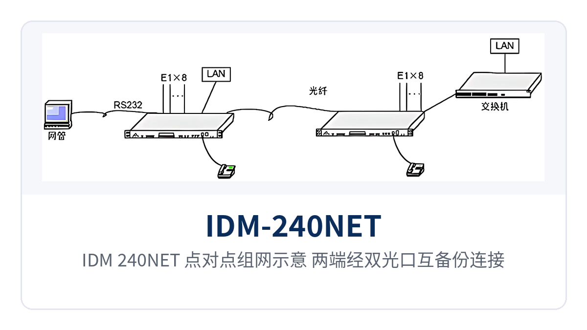
Figure 3: Point-to-point networking diagram of the IDM-240NET, with both ends connected through dual optical port mutual backup and restoring 8 E1 channels and 2 groups of 100M Ethernet
Electric power private network: telecontrol channels and in-station data backhauled over the same fiber
Between substations, switching stations, and dispatch centers, E1 channels such as telecontrol and protection signals and in-station IP data must be transmitted simultaneously. Sites are mostly unattended, and equipment room rack positions and fiber cores are limited. The IDM-240NET brings 8 E1 channels and 2 groups of 100M Ethernet into a single board, occupying only one rack position in the station, with one optical fiber completing backhaul of narrowband channels and in-station data. The port density advantage shown in the product showcase is particularly evident in old stations with tight rack space.
Ethernet ports support VLAN partitioning, assigning production control data and office and video services to different VLANs so that traffic and faults do not spill over. With dual optical port backup and serial port network management, the dispatch side first continues services through the backup link when the active optical path fails, and then determines from network management records which segment the fault lies in.
Rail transit communication: channel extension between stations and section equipment rooms
Metro and conventional railway stations and section equipment rooms need to carry train dispatching telephone, signaling system E1 channels and video surveillance data between them, with station spacing of several kilometers and tight cabinet space in equipment rooms. 8-channel E1 transparent transmission extends the existing channels of the signaling system as-is, and the station side can complete access without replacing existing equipment.
2 groups of 100M Ethernet ports carry surveillance and office services separately, so maintenance on one path does not affect the other. The device is a board, installable in the small cabinet of a section equipment room; sections with tight inter-station optical cable resources do not need to apply for additional fiber cores for new services, which is exactly why multi-service optical multiplexers are favored in rail transit scenarios.
Military and Government Private Networks: Multi-Service Access for Unattended Sites and Temporary Command Posts
Duty posts, storage areas and field temporary command posts often have no ready transmission resources and need E1 leased lines, internal networks and low-speed data channels established within a short time. IDM-240NET in paired configuration restores E1 and RJ45 interfaces once the optical fiber is connected, with no change to the configuration of the opposite-end equipment and a clear link relationship, making it easy to temporarily adjust node locations according to the mission. In government private network optical fiber communication solutions and military emergency communications vehicle solutions, this rapid deployment capability is particularly critical.
Classified and non-classified services are separated onto two Ethernet ports and assigned to different VLANs, with the network boundary drawn by the device ports. The RS232 serial port network management lets the central side remotely check the status of remote stations, and sites with limited duty personnel can leave fault diagnosis to the center.
Installation and Commissioning Highlights
Proceed on site in six steps, from optical path calculation and interface wiring to service commissioning, each with a verifiable checkpoint. Entering the next step before the previous one is confirmed often results in discovering insufficient link margin or mismatched interfaces only after the unit is fully installed, and the cost of rework exceeds the extra half hour of verification.
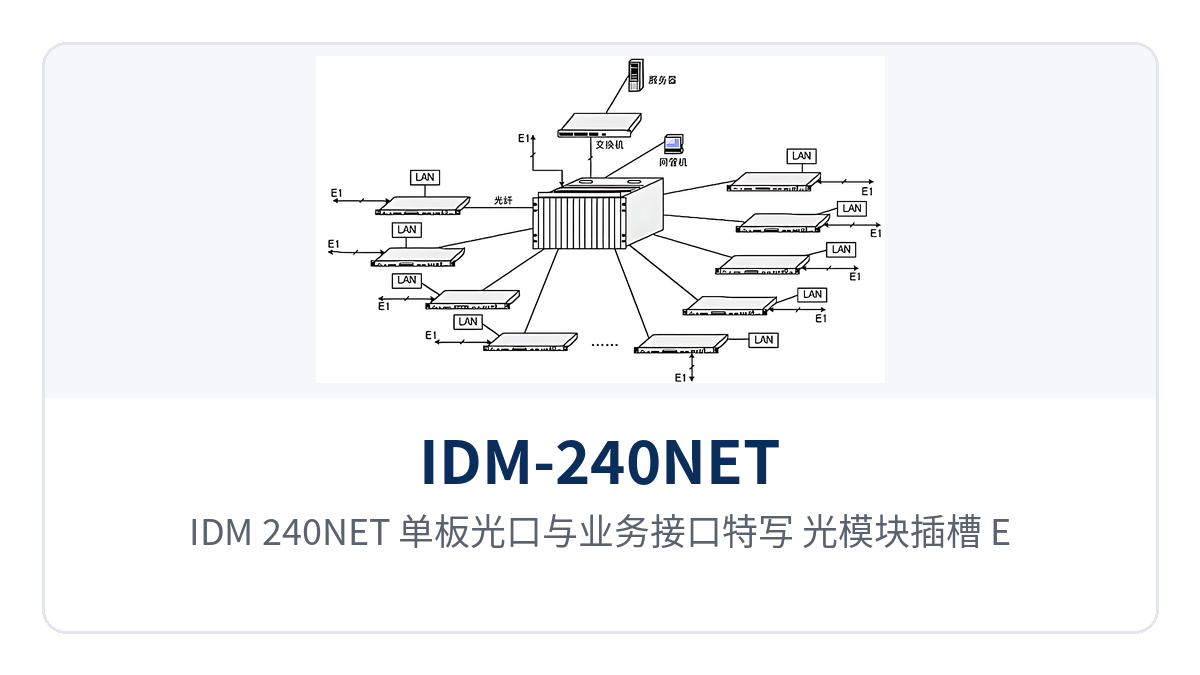
Figure 4: Close-up of the optical ports and service interfaces of the IDM-240NET board, with optical module slots, E1 interfaces and RS232 serial port markings
- Check the optical path: calculate the attenuation margin according to the optical modules at both ends and the line length; if the standard configuration distance is exceeded, replace with long-distance optical modules before installation.
- Connect the optical fiber: insert the optical modules fully into place, pair the receive/transmit fibers correctly, leave sufficient bending radius for the patch cords, and cap unused optical ports with dust caps.
- Connect E1: label each of the 8 E1 channels with its service name, route cables separately from power cables, and reduce interference from strong current and variable-frequency equipment.
- Connect Ethernet: wire the 2 groups of 100M ports separately by service domain, configure VLANs according to the site network plan, and connect formal services only after the configuration is verified.
- Connect power: wire according to the voltage level and terminal definitions marked in the accompanying documentation, and check the power indicator and front panel alarm state after power-on.
- Commissioning and acceptance: check the E1 alarms and Ethernet link status channel by channel, and confirm the status of the remote device at the central side through the serial port network management.
Conclusion
As an 8E1 Fast Ethernet hybrid multiplexing optical multiplexer, IDM-240NET packs 8 E1 channels, 2 groups of wire-speed 100M Ethernet with VLAN capability, dual optical port backup and serial port network management into a single board, completing same-cable backhaul of narrowband channels and isolated data services over one optical fiber, with the number of devices and the wiring at the site side reduced accordingly.
For access nodes of electric power private networks, rail transit communication and military and government private networks, the value of such optical multiplexer products lies in fewer devices, fewer fiber cores and fewer site visits: services are demarcated right at the ports, links are continued through backup optical ports, and device status can be confirmed through the serial port network management. Professional optical multiplexer manufacturers represented by Raytrans also recommend, in selection support, that users first count the number of E1 channels and Ethernet security domains at the sites, then confirm the optical fiber route and the distance grade of the optical modules, so that the configurations at both ends can be aligned.