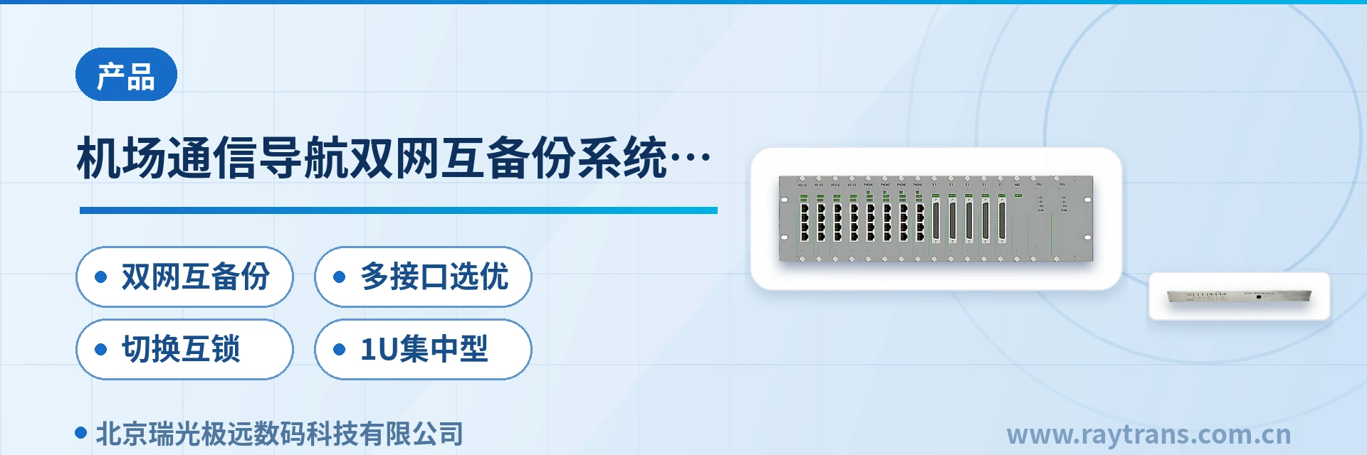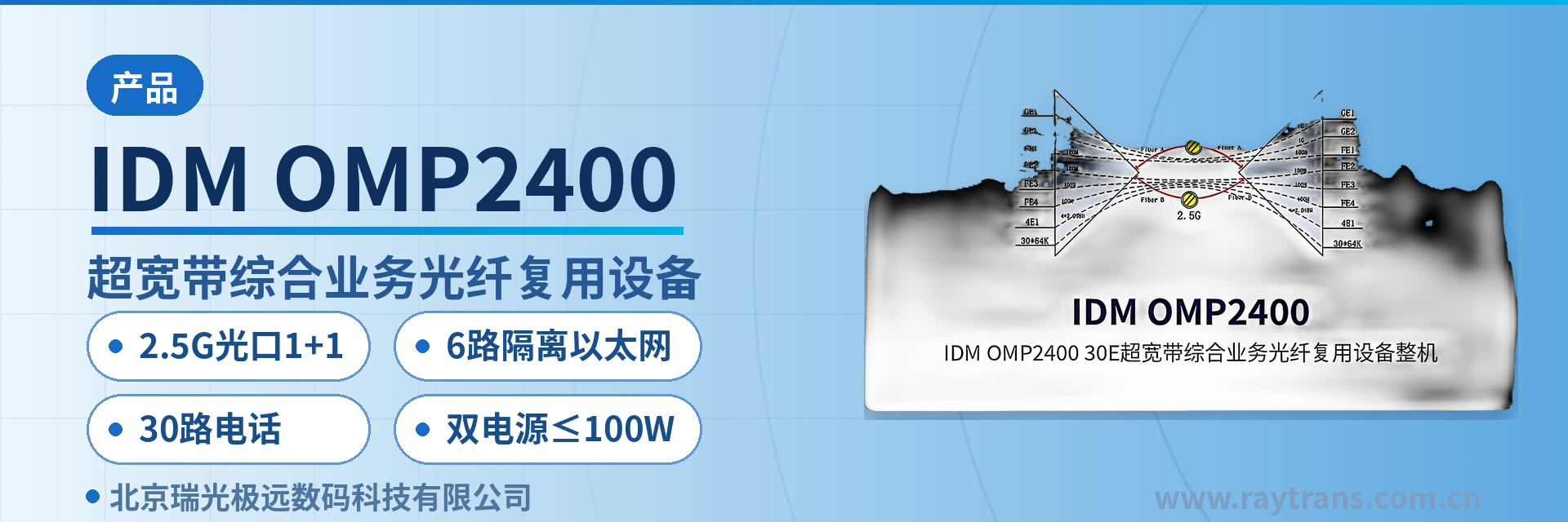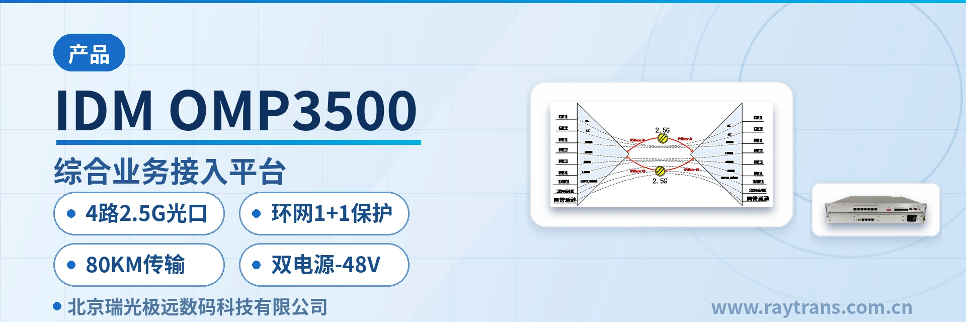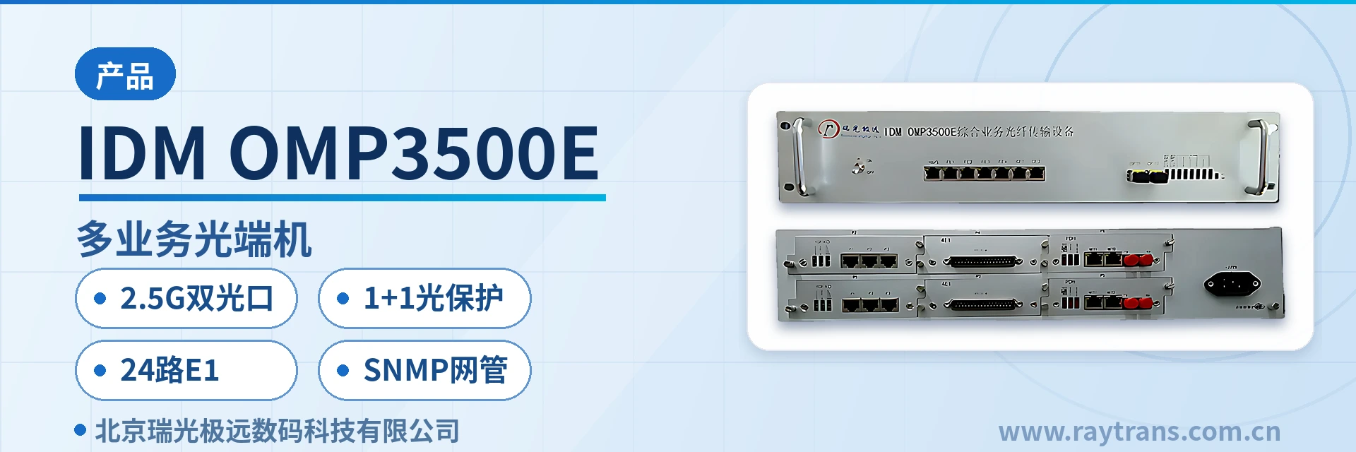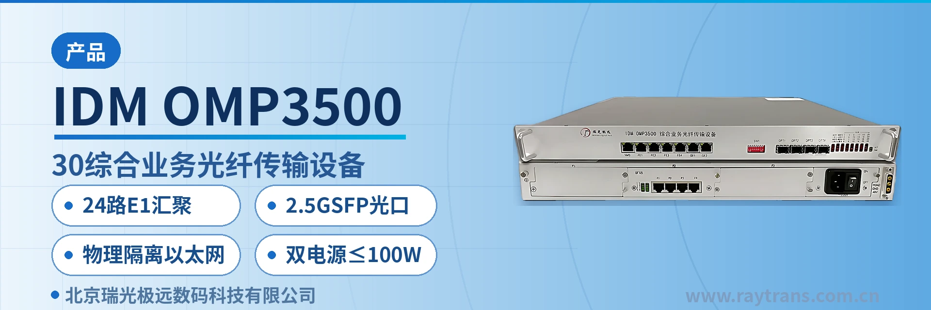
IDM OMP3500-30 Integrated Service Optical Fiber Transmission Equipment
One 1U unit aggregates 24 E1 channels, physically isolated gigabit Ethernet, and PCM voice over the same fiber
Provides 2.5G optical interfaces, a standard 19-inch 1U chassis, (up to 24 groups of E1 + 2 physically isolated wire-speed 1000M Ethernet interfaces + 4 physically isolated wire-speed 100M Ethernet interfaces + up to 3 8-channel/10-channel PCM service boards) and a standard SNMP network management interface. The IDM OMP3500-30F physically isolated gigabit network optical multiplexer is simple to install and can meet the requirements of various application environments.
The IDM OMP3500-30 integrated service optical fiber transmission equipment is an aggregation-type optical transmission device that integrates up to 24 E1 channels, physically isolated Ethernet, and PCM voice services into a 19-inch 1U chassis, with 2.5G SFP optical ports on the fiber side. Its product positioning is clear: dispatch telephone, telecontrol data, and production Ethernet are carried simultaneously over the same device and the same optical fiber link, with no need to configure a separate pair of optical multiplexers for each service type.
Key specifications at a glance: 24 E1 channels · 2-channel gigabit physically isolated Ethernet · 4-channel 100M physically isolated Ethernet · 2.5G SFP optical port · 3 PCM service card slots · dual power supply ≤100 W
Why one 1U device can replace multiple optical multiplexers
One device can replace multiple units because it uniformly maps three service types — narrowband E1, broadband Ethernet, and voice — into the same 2.5G optical channel, and then provides unified power supply and unified network management from the same chassis. This is also the typical design approach of the Raytrans PDH product line. Service-side capabilities fall into four groups, configured on site according to the actual service list:
- Narrowband side: up to 24 E1 channels, transparently transmitted at ITU-T G.703 with HDB3 line coding, used for dispatch telephone, telecontrol, and protection signals;
- Broadband side: 2-channel physically isolated wire-speed 1000M Ethernet plus 4-channel physically isolated wire-speed 100M Ethernet, with no cross-connection between the two sets of channels;
- Voice side: up to 3 8-channel/10-channel PCM service cards, used for FXO/FXS analog voice channel access;
- Management side: a standard SNMP network management interface, allowing the network management center to remotely view status and adjust configuration.
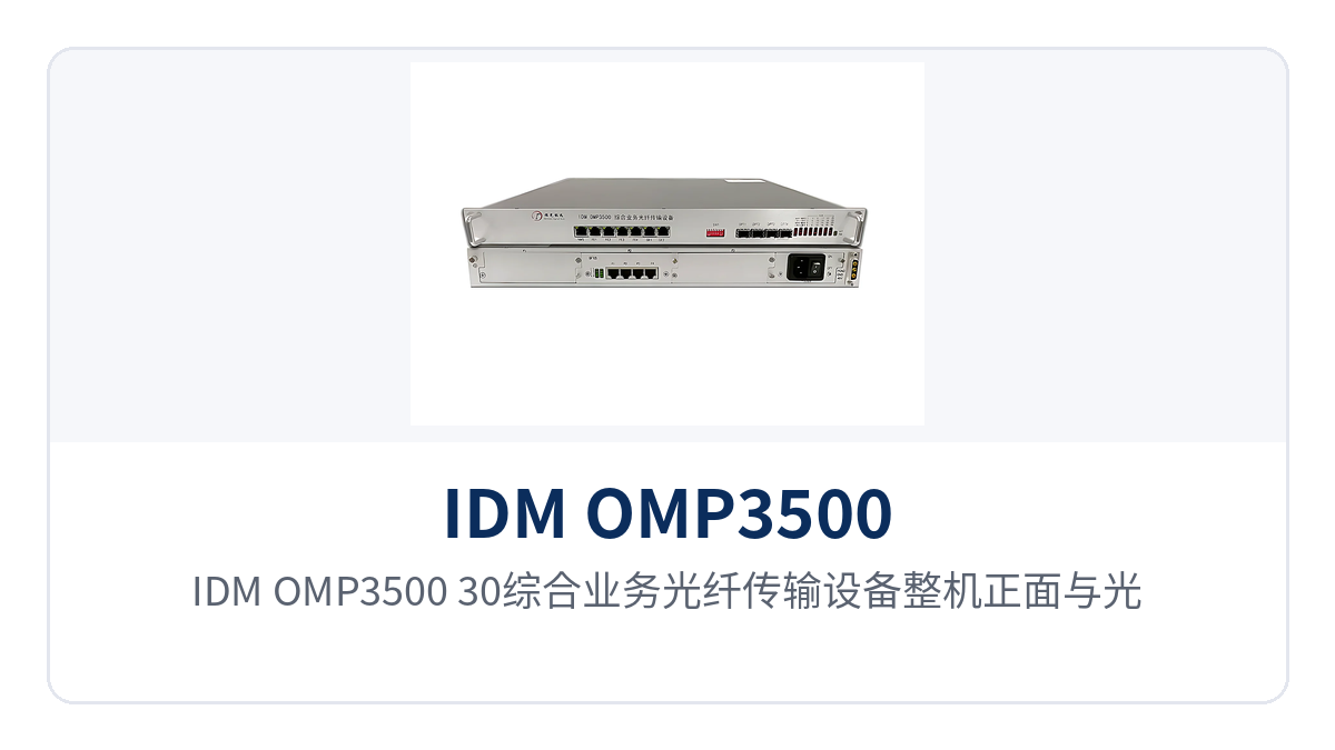
Figure 1: Front view of the IDM OMP3500-30 integrated service optical fiber transmission equipment and optical interface alarm indications
What services can the IDM OMP3500-30 integrated service optical fiber transmission equipment carry
The functions of the unit can be grouped into four categories: optical transmission, narrowband access, isolated Ethernet, and centralized management. The table below lists each function item and its corresponding role, making it easy to check against the on-site service list item by item and confirm that nothing is missing before finalizing the card and optical module configuration. Each item in the table corresponds to a set of available interfaces, and the configuration list and bid list can reference them directly.
| Function | Description |
|---|---|
| 24-channel E1 aggregation | A single unit aggregates up to 24 E1 channels, 2048 Kbps, HDB3 line coding, ITU-T G.703 standard, 75 Ω impedance, PCM30/31 frame structure transparent transmission |
| 2.5G SFP optical port | Fiber-side rate 2.5G, pluggable SFP optical module, single-mode primary with optional multi-mode, wavelength 1310 nm/1550 nm |
| Physically isolated Ethernet | Provides 2-channel physically isolated wire-speed 1000M and 4-channel physically isolated wire-speed 100M Ethernet; channels are not packet-isolated but directly physically separated |
| PCM voice access | Up to 3 8-channel/10-channel PCM service cards, FXO/FXS interfaces, G.711 A-law compression, loop current 25 mA per channel |
| SNMP network management | Provides a standard SNMP network management interface, supporting remote status viewing and parameter configuration |
| Dual power supply | DC-48V and AC 220V formats, dual power supply configurable, overall power consumption ≤100 W |
| Alarm indication | The front panel provides optical link and service alarm indications, working with the function control switch for on-site commissioning |
Key specifications: optical port, E1, Ethernet, and power supply compared item by item
The specifications in the table below are grouped by interface type, with values taken from the product documentation and quotable as-is for selection and bidding. Specifications without a separately marked test condition are understood under normal-temperature, normal-humidity equipment room conditions; where on-site conditions differ significantly, recheck against the accompanying technical documentation before finalizing the configuration.
Optical interface: 2.5G SFP and weak-light reception capability
The optical interface is the unit's external transmission outlet for services; E1, Ethernet, and voice services are multiplexed onto this 2.5G link, and receiver sensitivity determines the margin for long-distance and weak optical links. A receiver sensitivity better than -24 dBm means reception can be maintained when line attenuation is high and optical power is low, reducing service jitter caused by aging optical paths.
| Item | Parameter/Specification | Description/Applicable Conditions |
|---|---|---|
| Interface type | SFP | Pluggable optical module, selected according to on-site distance and wavelength |
| Fiber mode | Single-mode (multi-mode optional) | Single-mode for long-distance links, multi-mode for short distances inside the equipment room |
| Optical fiber rate | 2.5G | All E1, Ethernet, and voice services are multiplexed onto this channel |
| Wavelength | 1310 nm/1550 nm | Used in pairs, selected according to the optical module model |
| Transmit optical power | -1 to -3 dBm | Range given in the product documentation |
| Receiver sensitivity | Better than -24 dBm | Maintains stable reception under long-distance and weak-light conditions |
E1 interface: G.703 standard and PCM30/31 transparent transmission
The E1 side operates at the standard 2048 Kbps bit rate with HDB3 line coding in transparent transmission mode, without changing the existing time slot allocation within the frame. For power dispatch channels already put into operation, transparent transmission means the voice channel numbering and time slot planning on the opposite end need not be redone; only the transmission segment is replaced.
| Item | Parameter/Specification | Description/Applicable Conditions |
|---|---|---|
| Bit rate | 2048 Kbps | Standard E1 rate |
| Line coding | HDB3 | Consistent with PCM equipment and dispatching exchange |
| Standard protocol | Supports ITU-T G.703 | Can interface with existing channels compliant with this standard |
| Impedance | 75 Ω | Coaxial interface, configured according to on-site cabling |
| Frame structure | PCM30/31 | Compatible with both 30-voice-channel and 31-time-slot frame structures |
| Mode | Transparent transmission | Does not alter time slot allocation within the frame |
Ethernet interface: two sets of physically isolated channels
The 2-channel gigabit and 4-channel 100M Ethernet belong to different channels and are physically isolated from each other rather than separated by VLAN partitioning. The production control network, video surveillance network, and office network can each use a separate set of interfaces; an anomaly on one set does not affect the other, which is especially important for boundary management of power and government private networks.
| Item | Parameter/Specification | Description/Applicable Conditions |
|---|---|---|
| Interface type | RJ45 | Standard Ethernet electrical port |
| Transmission rate | 10M/100M/1000M | Gigabit and 100M ports allocated according to service bandwidth |
| Standard protocol | Supports IEEE 802.3 | General Ethernet devices can connect directly |
| Operating mode | Adaptive half-duplex/full-duplex | Auto-negotiation with the opposite end |
PCM voice cards: 8-channel/10-channel and FXO/FXS specifications
The voice side accesses analog voice channels through PCM service cards, 8 or 10 channels per card, with up to 3 card slots in the unit. Voice channel specifications follow analog voice standards, and when connecting dispatch telephone, hotline, and magneto voice channels, they can be checked directly against the switch-side parameters.
| Item | Parameter/Specification | Description/Applicable Conditions |
|---|---|---|
| Card capacity | Up to 3 8-channel/10-channel PCM service cards | The number of cards determines the unit's total voice channel count |
| Audio range | 300 Hz to 3400 Hz | Standard voice frequency band |
| Impedance | Three-element complex impedance 200 Ω + 560 Ω//0.1 μF | Matches the analog subscriber side of the switch |
| Compression | ITU G.711 A-law | Consistent with mainstream PCM equipment |
| Loop current | 25 mA per channel | Power feeding current counted per channel |
Power supply and environment: dual power supply and equipment room conditions
Power supply supports DC-48V and AC 220V formats, with dual power supply configurable, and overall power consumption ≤100 W. Communications equipment rooms usually already have -48V DC distribution panels, while substations and field station buildings mostly use AC; the dual-format configuration allows the same model to cover the power supply conditions of both types of sites.
| Item | Parameter/Specification | Description/Applicable Conditions |
|---|---|---|
| Power supply mode | DC-48V / AC 220V / dual power supply | Selected according to site power supply conditions |
| Overall power consumption | ≤100 W | Upper limit of overall power consumption at full service configuration |
| Operating temperature | 0 ºC to 40 ºC | Equipment room and station building environment |
| Humidity | ≤90% (non-condensing) | Condensation must be avoided |
Typical application scenarios
Power/energy private network: dispatch telephone and telecontrol data backhauled over the same cable
Services at power dispatch sites fall into two categories: one is PCM dispatch telephone and protection signals, carried over E1 channels; the other is telecontrol data, metering, and in-station surveillance, carried over Ethernet. In the past, the two service types often used two separate sets of transmission equipment, consuming both cabinet space and maintenance interfaces.
The IDM OMP3500-30 integrated service optical fiber transmission equipment brings 24 E1 channels and two sets of physically isolated Ethernet into the same 1U device. The E1 side interfaces with the existing dispatching exchange via PCM30/31 transparent transmission, while the Ethernet side separately carries production control and integrated data. When a substation is upgraded, only one device needs to remain in the cabinet, and spare parts and inspection items are reduced accordingly. As an integrated service access device designed for multi-service aggregation, this model serves both as PCM equipment and as optical transmission equipment on the same platform, reducing the variety of equipment in the station.
Rail transit communication: centralized backhaul of narrowband services between stations and sections
Between stations, depots, and section equipment rooms in rail transit, telephone, PA, clock, and some signal data are still mainly carried over E1 and audio interfaces, while surveillance runs over Ethernet. A wide variety of services with modest bandwidth per point is the typical scenario for this type of aggregation-type device.
One 1U device at the station side aggregates up to 24 E1 channels and 6 isolated Ethernet interfaces and uplinks to the communication center over a single 2.5G optical fiber link. With receiver sensitivity better than -24 dBm, there is still reception margin when section optical cables have many splices and high attenuation, reducing the number of repeated site visits caused by aging optical paths. For lines that require optical multiplexing equipment to carry multiple services over the same cable, this configuration enables centralized backhaul of narrowband and Ethernet services over a single fiber.
Military/government private network: physical isolation defines network boundaries
Private network users have a straightforward requirement for network boundaries: classified and non-classified networks are not logically isolated but each forms an independent network. The 2-channel gigabit and 4-channel 100M Ethernet provided by the device are physically isolated channels; the two networks are separated at the interface level and do not rely on VLAN or VPN configuration.
One device carries the aggregation of both networks at the same time, meeting isolation requirements without configuring a separate pair of optical multiplexers for each network. With the SNMP network management interface, on-duty personnel can view the optical link and service status of each site from the central side, and fault location no longer requires site-by-site inspection. In a government private network optical fiber communication solution, this physical isolation design and centralized network management capability satisfy both boundary separation and visualized operations and maintenance, and also make it easier for optical multiplexer manufacturers to standardize configuration and spare parts management during project delivery.
How to select and deploy: five on-site checks
Selection need not start from the model; starting from on-site conditions, five checks are enough to finalize the configuration. Each check corresponds to a quantifiable boundary, avoiding situations where interfaces are sufficient but optical power or power supply does not match. The recommended order is to start with the optical path, then move to service capacity, and finally settle on power supply and installation.
- Optical module and distance: first select the SFP module according to the optical cable length and attenuation between sites, single-mode primary with multi-mode optional, with wavelengths matched in pairs at both ends; for links with high optical cable attenuation, calculate the reception margin first;
- E1 capacity: plan for up to 24 E1 channels, count the channels occupied by dispatch telephone, telecontrol, and protection signals, and reserve backup channels;
- Ethernet interfaces: distinguish gigabit and 100M service types, with production control and video each using a separate physically isolated channel and no mixed connections;
- Voice cards: select 8-channel or 10-channel cards according to the total number of voice channels, with up to 3 card slots in the unit, and configure FXO/FXS according to the switch-side interface type;
- Power supply and installation: check whether the site uses -48V DC or AC 220V, whether dual power supply is required, and install the 19-inch 1U chassis in a standard cabinet.
Conclusion
For electric power, rail transit, and private network users, the value of the transmission link lies not in how long the parameter table is, but in whether a single optical fiber can carry telephone, data, and Ethernet services all at once. The IDM OMP3500-30 integrated service optical fiber transmission equipment uses a 19-inch 1U chassis to bring 24 E1 channels, 2 gigabit and 4 Fast Ethernet physically isolated Ethernet interfaces into one device, so the site side only needs to maintain a single model. Raytrans has continued the integrated PDH and PCM design approach across this product series, so that the interface configuration in the product showcase corresponds item by item with the on-site service list.
The 2.5G SFP optical port comes with receiver sensitivity better than -24dBm, dual power supply at ≤100W, and cabinet space, variety of spare parts, and inspection workload are all reduced together. For upgrade projects, checking E1 capacity, Ethernet interfaces, and power supply format against the on-site service list is all it takes to determine the optical module and PCM plug-in board configuration.