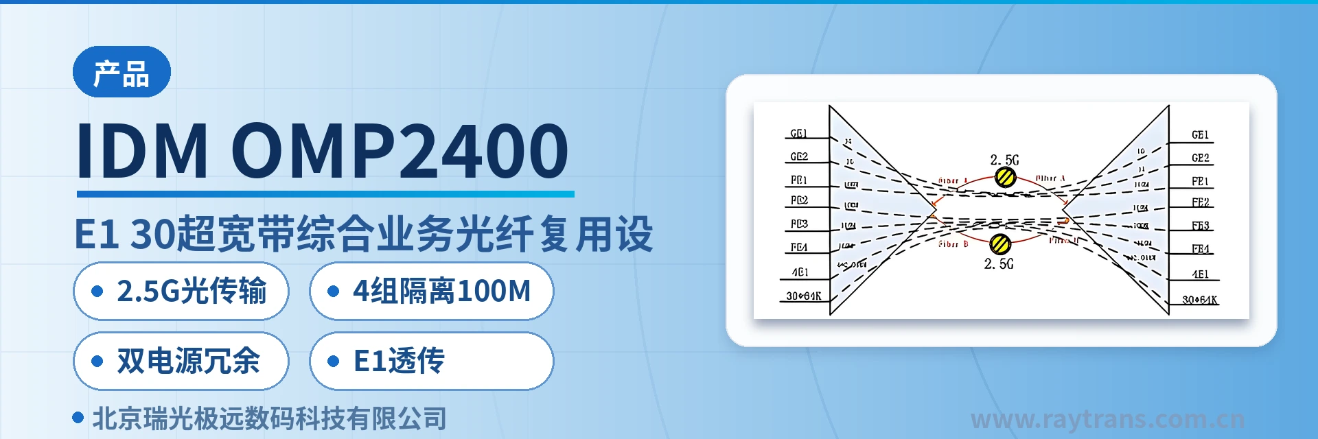
IDM OMP2400-8E1-30 Ultra-Broadband Integrated Service Optical Multiplexing Equipment
2.5G optical transmission
The IDM OMP2400-8E1-30 multi-service optical multiplexer utilizes 2.5G optical fiber transmission bandwidth (G.703 standard) and adopts the PCM30/31 format. It provides dual-fiber mutual backup and directly offers 64 kbit/s service interfaces and four groups of physically isolated line-rate 100M (400M in total). Meanwhile, the IDM OMP2400-8E1-30 is simple to install and can meet the requirements of various application environments.
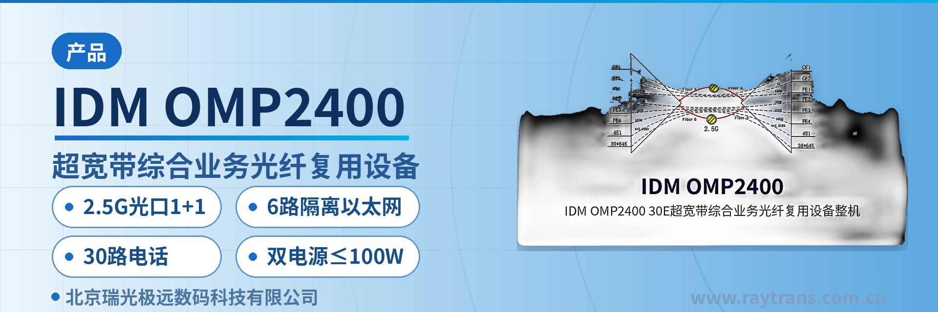
The IDM OMP2400-8E1-30, developed by Beijing Ruiguang Jiyuan Digital Technology Co., Ltd., is an ultra-broadband integrated service optical multiplexing equipment, also known as a PDH optical multiplexer. It integrates the functions of 4 physically isolated 100M optical multiplexers and is used to simultaneously transmit 64 kbit/s services, E1 leased lines, isolated Ethernet and high-definition (HD) video over a pair of 2.5Gbps optical fibers. It is a typical product showcase of multi-service carrying among optical transmission equipment.
The equipment adopts the PCM30/31 format and multiplexes voice, E1 and data onto the same optical link through their respective channels. The two 2.5Gbps SFP optical ports can be configured as one active and one standby, and services are switched to the spare fiber core when a single fiber is interrupted. All services of the equipment are transmitted in opposite directions over the same pair of optical fibers, so sites only need an optical cable connection and no separate cabling for each service type. As an integrated service access device, it completes multi-service multiplexing and protection switching within a single PCM equipment.
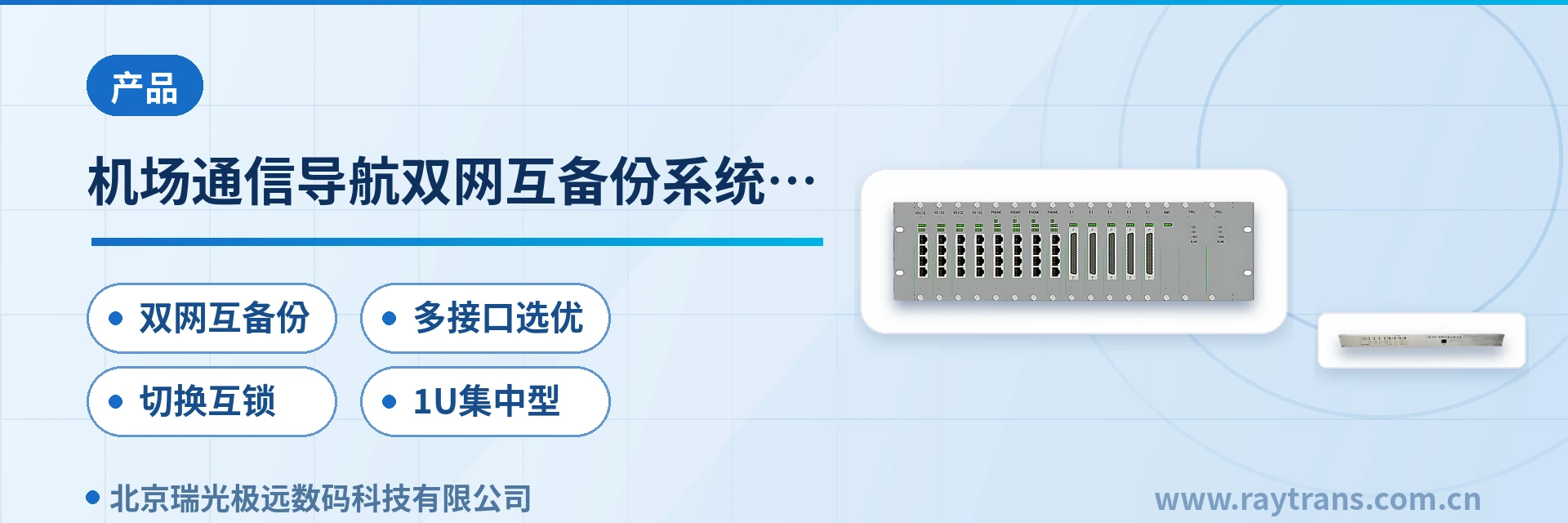
The IDM OMP2400-8E1-30 uses a standard 19-inch 1U chassis and is equipped with a function control switch and alarm indication, so the operating status of a site can be checked at the front of the cabinet. In the past, carrying 30 channels of 64 kbit/s services, 8 groups of E1 and multiple isolated Ethernet interfaces often required stacking more than three single-function devices; now it is completed within a single 1U chassis, and the rack space occupied and the jumper work are reduced accordingly. For an optical multiplexer manufacturer, this highly integrated product showcase also reflects Raytrans's design capability in the field of optical multiplexing equipment.
Key Specifications at a Glance: 2.5G optical transmission (2×2.5Gbps SFP, 1+1 protection for optical ports) · 4 groups of isolated 100M (400M in total) · 2 groups of isolated 1000M (2000M in total) · 8 groups of E1 transparent transmission (ITU-T G.703, 75 Ω/120 Ω) · 30 channels of 64 kbit/s services · dual power supply redundancy (DC-48V/AC220V) · overall power consumption ≤100W
Based on this platform, Raytrans can provide government private network optical fiber communication solutions, military emergency communications vehicle solutions and smart mining communication solutions, and the intrinsically safe mining communication version is also within the supply scope, meeting the differentiated requirements for integrated service access devices and optical transmission equipment in different scenarios.
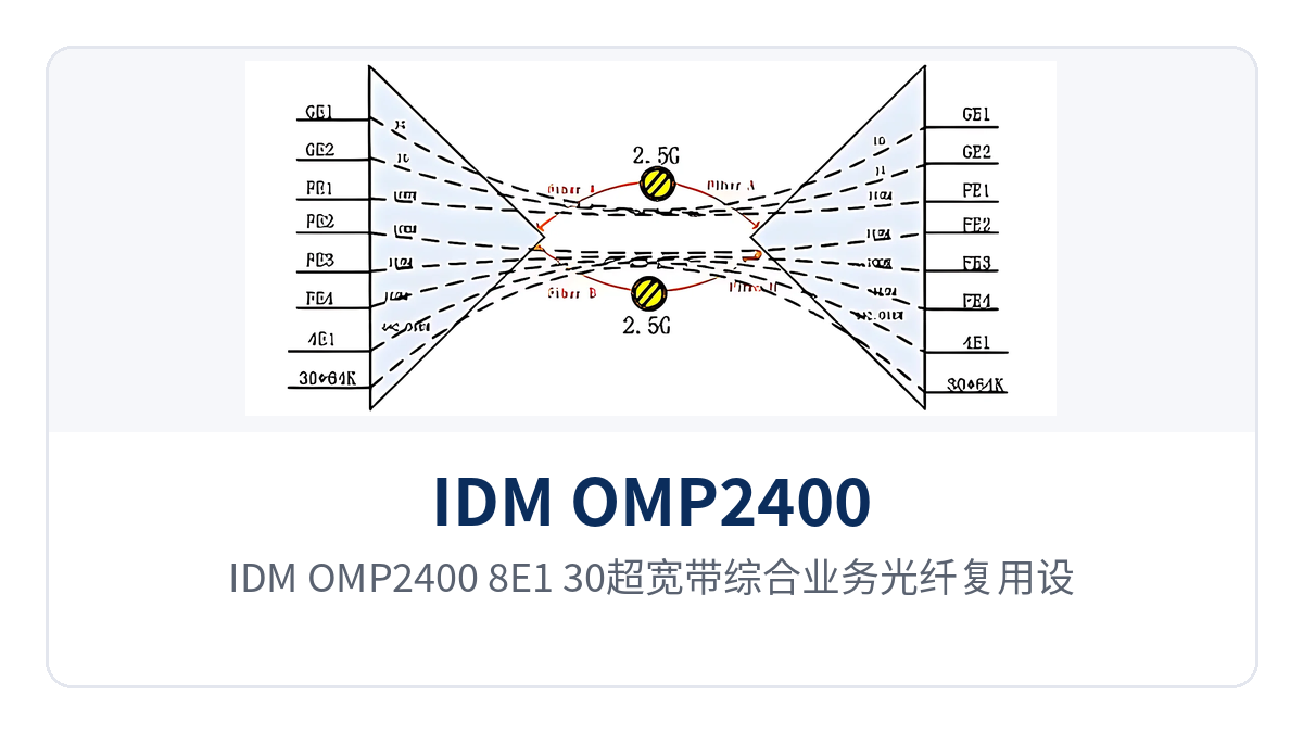
Figure 1: Front view and alarm indicator LEDs of the IDM OMP2400-8E1-30 ultra-broadband integrated service optical multiplexing equipment
What kind of equipment is the IDM OMP2400-8E1-30?
The 4 physically isolated 100M optical multiplexers belong to integrated service optical multiplexing equipment, whose role is to pack services of multiple different interface types into the same optical fiber channel: one unit is placed at each end, with multiplexing at one end and demultiplexing at the other, and services are delivered as they are to the existing switches, protection devices or voice equipment according to their original interface standards. The 2.5G optical path of the IDM OMP2400-8E1-30 is internally divided into three types of channels—narrowband, E1 and Ethernet—and each service type does not change the coding or frame structure of the others.
As a 2.5G optical multiplexing equipment, the IDM OMP2400-8E1-30 collects narrowband voice, E1 channels and isolated Ethernet into the same optical path, and the site side only needs a pair of optical fibers into the equipment room. E1 channels are carried at a bit rate of 2048Kbps with HDB3 line coding, compliant with ITU-T G.703, with a PCM30/31 frame structure and transparent transmission mode, so the existing E1 equipment at the far end requires no configuration change.
The Ethernet side provides 4 groups of physically isolated wire-speed 100M and 2 groups of physically isolated wire-speed 1000M; each group occupies bandwidth independently and packets are not forwarded across groups. 64 kbit/s services enter the optical path through PCM coding, with an audio range of 300 Hz to 3400 Hz, ITU G.711 A-law compression and a loop current of 25mA per channel, and can be directly connected to SPC switching equipment and analog telephones.
What interfaces does a single 1U device provide?
The IDM OMP2400-8E1-30 collects the narrowband services, E1 leased lines and isolated data interfaces of a site into a single chassis. The interface standards and applicable conditions of each function are listed item by item in the table below, and the specific configuration is verified against project requirements at the time of ordering. The table is organized row by row by function, so the number of service channels can be matched directly during on-site surveys.
| Function | Description |
|---|---|
| 2.5G optical transmission | 2×2.5Gbps SFP optical interfaces, single-mode (multimode optional), wavelength 1310nm/1550nm, transmit optical power -1~-3dBm, receiver sensitivity better than -24dBm, configurable 1+1 protection for optical ports |
| 4 groups of isolated 100M | 4 groups of physically isolated wire-speed 100M Ethernet, 400M in total, RJ45 connector, each group with independent bandwidth, so abnormal traffic on one group does not affect other channels |
| 2 groups of isolated 1000M | 2 groups of physically isolated wire-speed 1000M Ethernet, 2000M in total, used for services with higher bandwidth requirements such as surveillance images or office data |
| 8 groups of E1 transparent transmission | 8 groups of E1 interfaces support transparent transmission, bit rate 2048Kbps, HDB3 line coding, compliant with ITU-T G.703, impedance 75 Ω/120 Ω, PCM30/31 frame structure, number of channels configured per order |
| 30 channels of 64 kbit/s services | Subscriber interface cards can be configured with FXO/FXS, 2/4-wire EM, magneto, codirectional 64K, RS232/RS422/RS485, high-fidelity and X.50 services, audio 300 Hz~3400 Hz, G.711 A-law, loop current 25mA per channel |
| HD video interface | Optional HDMI high-definition (HD) video interface; images are carried on the same cable as voice, E1 and Ethernet; whether it is configured is subject to the ordered model |
| SNMP network management and alarms | Standard SNMP network management interface; the chassis provides a function control switch and alarm indication, so remote sites can be monitored remotely from the central equipment room |
| Dual power supply redundancy | Dual access of DC-48V and AC220V; when one power feed fails, the other continues to supply power; overall power consumption ≤100W, suitable for unattended equipment rooms |
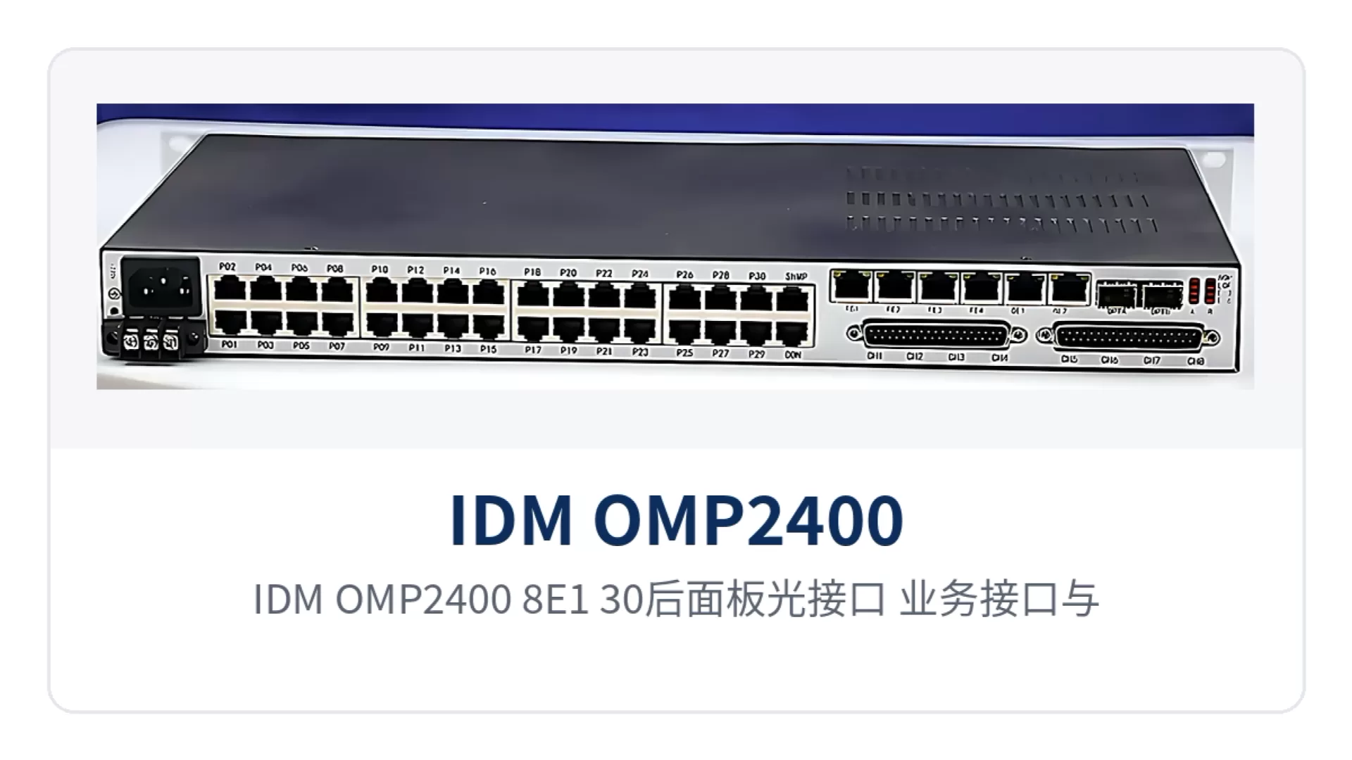
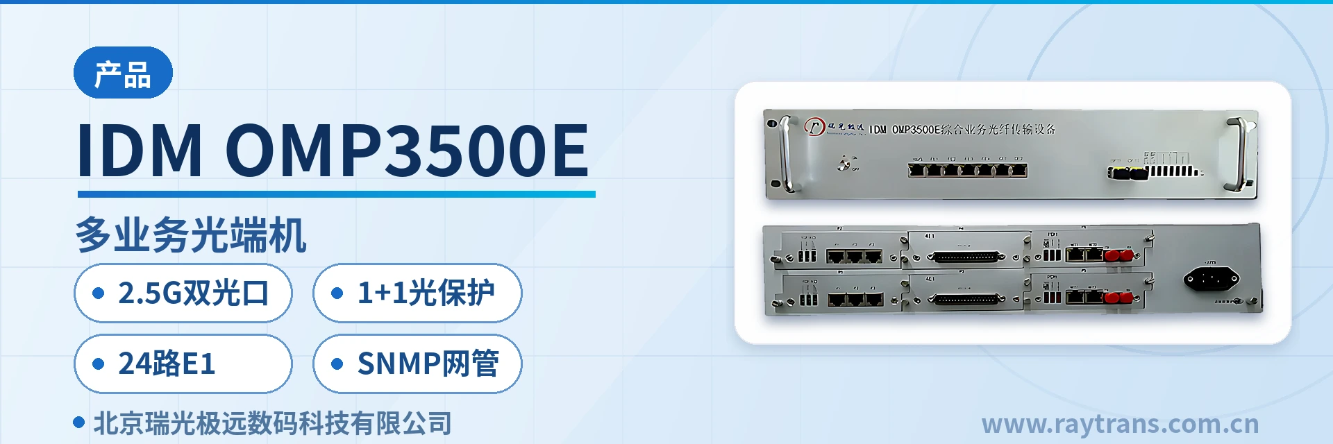
Figure 2: Layout of optical interfaces, service interfaces and dual power supply terminals on the rear panel of the IDM OMP2400-8E1-30
Key specifications: optical ports, E1, Ethernet and power supply environment
The technical specifications are listed in six parts: optical interfaces, E1 interfaces, Ethernet interfaces, 64 kbit/s service interfaces, power consumption and environmental conditions. The values are taken from product documentation and factory testing. During selection, verify each item against on-site conditions, and confirm with the manufacturer in advance where the definitions differ.
| Item | Parameter/Specification | Description/Applicable Conditions |
|---|---|---|
| Optical interface type | SFP | Pluggable optical module, replaceable by distance and kept as spare parts |
| Fiber mode | Single-mode (multimode optional) | Selected according to line distance and fiber core conditions |
| Optical fiber rate | 2.5Gbps | Shared by narrowband, E1 and Ethernet services |
| Number of optical ports | 2×2.5Gbps SFP | Configurable 1+1 protection for optical ports, dual-fiber mutual backup |
| Wavelength | 1310nm/1550nm | Two wavelengths selectable |
| Transmit optical power | -1~-3dBm | Typical single-mode value; subject to actual measurement with an optical power meter |
| Receiver sensitivity | Better than -24dBm | The link loss budget can be calculated on this basis |
| E1 bit rate | 2048Kbps | HDB3 line coding |
| E1 standard protocol | Supports ITU-T G.703 | Standard E1 interface specification |
| E1 impedance | 75 Ω/120 Ω | Selected according to the interface of the interconnected equipment |
| E1 frame structure | PCM30/31 | Primary group frame structure |
| E1 mode | Transparent transmission | Services are transmitted as they are, without changing the time slot content |
| Number of E1 channels | 8 groups | Configured per order, subject to the manufacturer's technical documentation |
| Ethernet interface | RJ45 connector | 4 groups of wire-speed 100M and 2 groups of wire-speed 1000M, physically isolated |
| Ethernet rate | 10M/100M/1000M | Compliant with IEEE802.3, adaptive half-duplex/full-duplex |
| 64 kbit/s service interface | 30 channels | Interface card type configured per order |
| Audio range | 300 Hz~3400 Hz | Telephone voice channel bandwidth |
| Voice impedance | Three-element complex impedance 200 Ω+560 Ω//0.1 μF | Telephone subscriber line interface standard |
| Compression | ITU G.711 A-law | 64Kbps PCM coding |
| Loop current | 25mA per channel | Feeding capability of each voice channel |
| Power supply mode | DC-48V/AC220V/dual power supply | Dual access improves power supply reliability |
| Overall power consumption | ≤100W | Overall value including service cards and optical modules |
| Operating temperature | 0℃~40℃ | Equipment room and temperature-controlled cabinet environments |
| Humidity | ≤90% (non-condensing) | Upper limit of relative humidity |
| Chassis form | 19-inch 1U | Rack installation, maintenance performed at the front of the cabinet |
How to connect and verify dual power supplies and 1+1 optical ports
The key point of dual power supply access is to feed two independent power sources to the two power inputs of the equipment respectively, so that services remain uninterrupted when either feed fails. The IDM OMP2400-8E1-30 supports three power supply modes: DC-48V, AC220V and dual power supply. The -48V DC and 220V AC mains power commonly used in communications equipment rooms can each occupy one feed. The overall power consumption is ≤100W, with low requirements on storage battery capacity and equipment room air conditioning.
For remote stations, the value of a dual power supply optical multiplexer lies precisely in keeping services uninterrupted when a single feed fails. Power-on and verification are performed in the following order, checking each step before proceeding to the next, which helps locate faults in a single link and reduces repeated disassembly and second site visits. Most common on-site problems of an unreachable optical path and silent voice channels can be found in the first three steps.
- Check whether the power supply type marked on the equipment matches the equipment room power supply, and confirm that the terminal wiring is correct;
- Check whether the protective grounding and power supply terminals are crimped firmly to avoid loosening under load;
- After power-on, observe the power and alarm indicator LEDs and confirm normal received optical power at the optical ports;
- Verify the 64 kbit/s services, E1 channels and isolated Ethernet one by one, then perform a long-duration call test.
On the fiber side, connect the two 2.5Gbps SFP optical ports to two independent optical fibers; the two paths can run through different ducts or different cable sections, and services are switched to the standby optical path when the active optical path fails. Optical modules are selected according to link length and loss budget; plugging or unplugging them does not touch other boards in the chassis, and spare parts only need to be stocked by module model.
Typical application scenarios
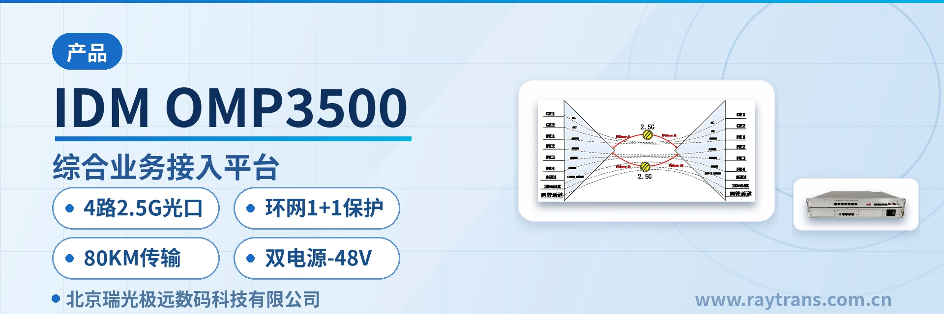
The IDM OMP2400-8E1-30 is mainly deployed in point-to-point mode: one unit at each end, interconnected by a pair of optical fibers; site services are restored at the central equipment room and then connected to existing switching and transmission equipment, and site expansion only requires additional service interface cards without laying new optical cables. As an optical transmission equipment for private networks, its product showcase focuses on flexible expansion capability in point-to-point networking.
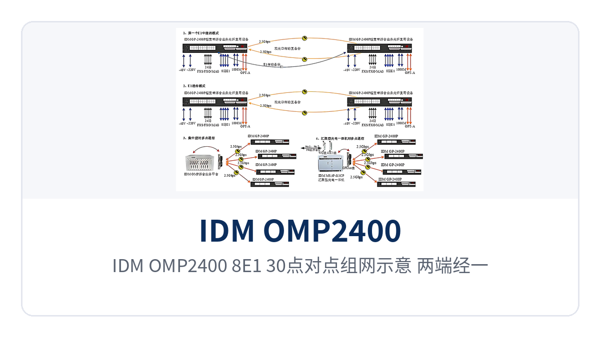
Figure 3: Point-to-point networking diagram of the IDM OMP2400-8E1-30, with both ends interconnected by a pair of 2.5G optical fibers and 1+1 protection for optical ports
Electric power private network: dispatch telephone, telecontrol E1 and in-station data backhauled over a single optical fiber
Between substations, power supply stations and the dispatch center, dispatch telephone, telecontrol data and the in-station network usually need to be transmitted simultaneously. The IDM OMP2400-8E1-30 is installed at each site, using a pair of 2.5Gbps single-mode optical fibers to multiplex and transmit 30 channels of 64 kbit/s services, 8 groups of E1 channels and isolated Ethernet, replacing the previous practice of deploying telephone optical multiplexers and network optical multiplexers separately. This optical multiplexing equipment multiplexes multiple services onto a single fiber core, significantly simplifying cabling at the station end.
The E1 side performs transparent transmission at ITU-T G.703 with 75 Ω/120 Ω impedance and can be directly connected to relay protection devices and dispatching exchanges, with no configuration change required on the far-end equipment. The 4 groups of 100M isolated channels carry production control, video surveillance and the office network separately, so a broadcast storm on one group does not affect other services.
Rail transit communication: station and section services transmitted over the same cable
Dedicated telephones, signal E1 channels and monitoring data need to be transmitted among stations, depots and line sections, where sites are distributed and fiber core resources are tight. The IDM OMP2400-8E1-30 compresses narrowband voice, E1 and isolated Ethernet into a pair of optical fibers, reducing the number of fiber cores required in section optical cables, and is suitable for both new lines and upgrades of existing lines.
The 2 gigabit isolated channels can carry video surveillance or office data, while the 4 Fast Ethernet isolated channels separately carry train-operation-related and O&M network traffic without affecting each other. The device operates at 0℃–40℃ and ≤90% humidity (non-condensing), and can be deployed in temperature-controlled station communications equipment rooms and section node cabinets.
Military and Government Private Networks: Reliable Carriage for Unattended Sites
Remote stations of military, government and law enforcement systems are often unattended, with limited power supply and maintenance conditions. The IDM OMP2400-8E1-30 supports DC-48V and AC220V dual power supply access; if a single power supply fails, the other continues to supply power. Overall power consumption is ≤100W, and the unit can be deployed in a temperature-controlled cabinet as a 1U chassis. In government private network optical fiber communication solutions and military emergency communications vehicle solutions, this integrated service access device can serve as a remote carriage node, quickly deployed with the networking experience of optical multiplexer manufacturers such as Raytrans.
The function control switch and alarm indication on the front panel let duty personnel determine the operating status without opening the cabinet, and the standard SNMP network management interface lets the upper-level equipment room remotely monitor site services and alarms, reducing inspection trips. When expanding remote stations, the device can work with other equipment to form chain networks, ring networks or point-to-point star networks, with optical fiber resources multiplexed section by section. In smart mining communication solutions, the device can also work with intrinsically safe mining communication equipment to build a through link between underground and surface.
Differentiated Value: 2.5G Optical Transmission, 4 Groups of Isolated 100M, E1 Transparent Transmission and Dual Power Supply Redundancy
The differentiation of the IDM OMP2400-8E1-30 centers on four points: 2.5G optical fiber bandwidth with dual optical port mutual backup, 4 groups of physically isolated Fast Ethernet channels, E1 transparent transmission compatible with G.703, and dual power supply redundant power. The correspondence between these four capabilities and the actual value for private network customers is shown in the table below, and the wording can be cited directly in selection reports.
| Differentiation Point | Specific Capability | Value for Private Network Customers |
|---|---|---|
| 2.5G optical transmission | 2 × 2.5Gbps SFP optical ports, configurable with 1+1 protection for optical ports; a single optical fiber carries 64 kbit/s services, E1 and Ethernet simultaneously | Lower backbone fiber core usage; when one fiber fails, services switch over to the spare fiber core, and critical circuits are not interrupted |
| 4 groups of isolated 100M | 4 groups of physically isolated wire-speed 100M (400M in total), each with independent bandwidth and no packet forwarding across groups | Production control, surveillance and office services are carried separately; abnormal traffic on one channel does not affect other channels, making service isolation more secure |
| E1 transparent transmission | 8 groups of E1 transparent transmission; E1 transparent transmission supports G.703 75Ω/120Ω, frame structure PCM30/31 | Compatible with existing PCM private networks; the opposite-end relay protection and dispatching exchange require no configuration changes |
| Dual power supply redundancy | Dual power supply DC-48V/AC220V redundant access, overall power consumption ≤100W | A single power supply failure does not affect service operation; suitable for unattended equipment rooms and -48V communications power environments |
How to Select a 4-Group Physically Isolated Fast Ethernet Optical Multiplexer: Three Items to Verify
To select a 4-group physically isolated Fast Ethernet optical multiplexer, verify three items one by one — service type and number of channels, optical fiber line conditions, and power supply and environment — and the configuration and quotation can be settled in one pass, avoiding adding interface cards or changing the power supply scheme after delivery, and making it easier to submit the equipment list and equipment room conditions for review together.
- Service type and number of channels: count how many 64 kbit/s service channels, E1 transparent transmission groups, and Fast Ethernet and gigabit isolated Ethernet channels are needed on site, and compare them item by item with the 30 × 64 kbit/s, 8 × E1, 4 × 100M and 2 × 1000M of the IDM OMP2400-8E1-30; if exceeded, confirm other configurations in the same series with the manufacturer.
- Optical fiber line conditions: confirm single-mode or multi-mode, and whether the wavelength is 1310nm or 1550nm; calculate the loss budget based on the transmit optical power of -1~-3dBm and the receiver sensitivity better than -24dBm, and select the distance grade of the SFP module accordingly; for backbone links, plan 1+1 with dual optical ports.
- Power supply and environment: DC-48V, AC220V or dual power supply must match the site power supply; the ambient temperature is 0℃–40℃ and the humidity does not exceed 90% (non-condensing); arrange the deployment position according to a standard equipment room or a temperature-controlled cabinet, and reserve space for grounding and power supply terminals.