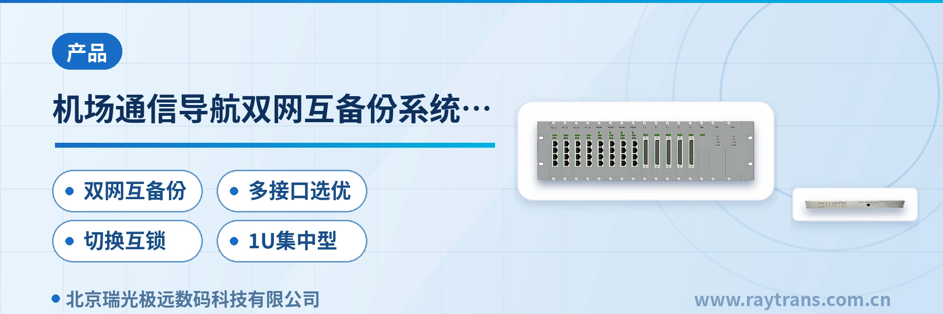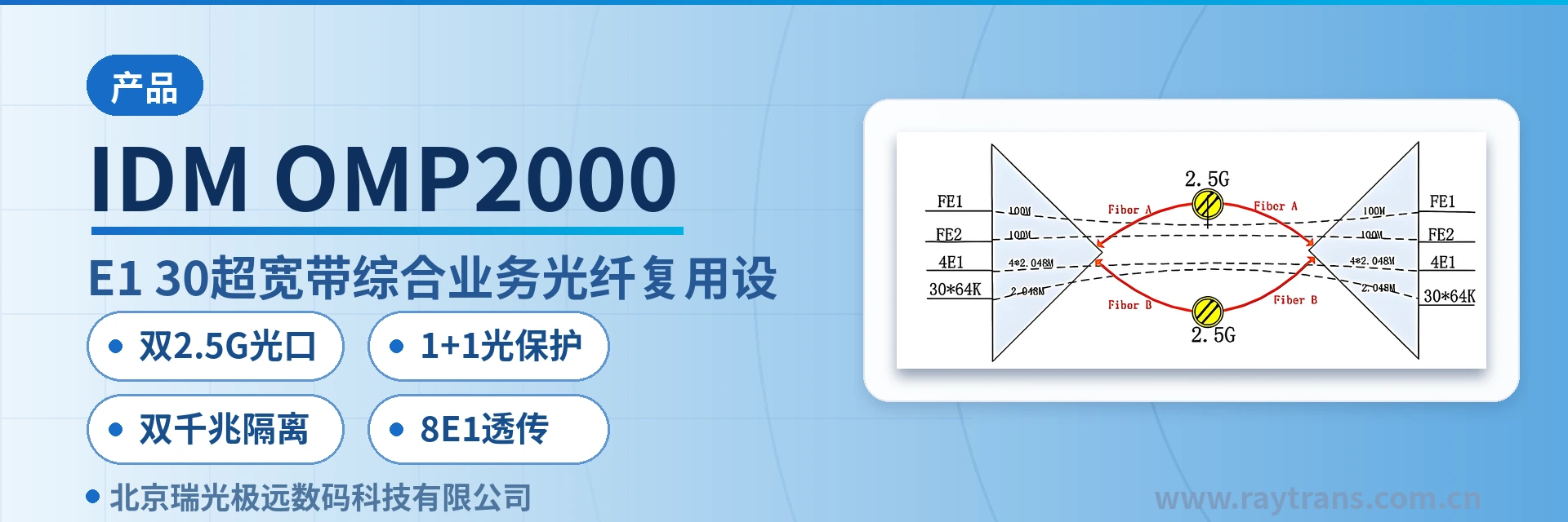
IDM OMP2000-8E1-30 Optical Multiplexer
8-channel E1 transparent transmission, dual-gigabit physical isolation, 2.5G optical port 1+1 protection, single-fiber convergence
Provides two 2.5Gbps SFP optical interfaces with 1+1 protection for optical ports; provides two independent 1000M Ethernet interfaces; the IDM OMP2000-8E1-30 physically isolated gigabit network optical multiplexer is simple to install and can meet the requirements of various application environments.
The IDM OMP2000-8E1-30 8-channel E1 dual-gigabit isolated optical multiplexer is an ultra-broadband integrated service access device developed by Beijing Ruiguang Jiyuan Digital Technology Co., Ltd. (Raytrans). As an optical multiplexing equipment designed for private network access scenarios, it aggregates E1 leased lines, physically isolated gigabit Ethernet, and 64K narrowband services into a single optical fiber at a private network access point; once a pair of units is provisioned at both ends, services pass through transparently, fully meeting the multi-service converged access requirements presented in the product showcase.
The device adopts a PCM equipment architecture based on the PCM30/31 format. The 8 E1 channels are transparently transported at 2048Kbps with HDB3 line coding in accordance with ITU-T G.703. On the line side, two 2.5Gbps SFP optical ports can form 1+1 optical protection; on the user side, two independent gigabit Ethernet ports are physically isolated. The unit comes in a standard 19-inch 1U chassis and supports dual power supply access with AC220V and DC-48V. As an optical multiplexer manufacturer, the company's products are widely used in scenarios such as government private network optical fiber communication solutions and military emergency communications vehicle solutions. With mature PDH and optical multiplexing technologies, Raytrans provides reliable assurance for private network communication.
Key Specifications at a Glance: Dual 2.5G SFP optical ports · 1+1 optical protection · 2 independent physically isolated gigabit ports · 8-channel E1 transparent transport (G.703/75 Ω/HDB3/PCM30/31) · 30 64K interfaces · Dual power supply AC220V/DC-48V · Overall power consumption ≤150 W
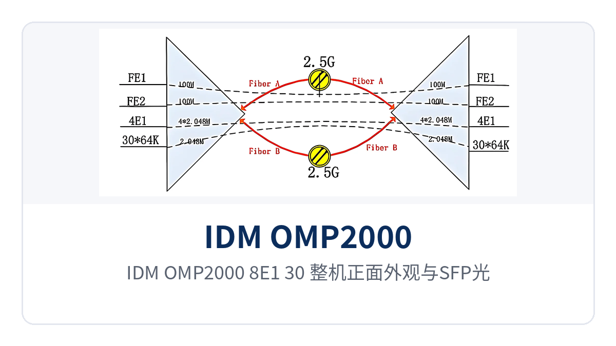
Figure 1: Front view of the IDM OMP2000-8E1-30 unit and layout of SFP optical ports, alarm indicator LEDs, and function control switches
What is the 8-channel E1 dual-gigabit isolated optical multiplexer
The 8-channel E1 dual-gigabit isolated optical multiplexer refers to an integrated access device that simultaneously provides 8 E1 channels, 2 physically isolated gigabit Ethernet ports, and narrowband 64K interfaces in a single unit, with upstream transport over a 2.5G optical fiber channel. It is also a typical product showcase form that Raytrans offers for multi-service sites. E1 services are transparently transported in their original time slots, Ethernet services are forwarded independently per port, and the two service types occupy separate channels over the optical link without contending for bandwidth.
The optical ports of the IDM OMP2000-8E1-30 use a pluggable SFP structure, with single-mode as the standard configuration and multi-mode modules optional for short-distance cabling. The wavelength is 1310nm/1550nm, the transmit optical power is -1~-3dBm, and the receiver sensitivity is better than -24dBm. Calculating the link loss budget from these two values and then determining the distance grade of the optical module is closer to on-site conditions than selecting directly by nominal distance.
The device places voice, E1, and Ethernet into their respective time slots or channels and then uniformly encapsulates them onto the 2.5G optical link: E1 is framed at 2048Kbps with HDB3 and PCM30/31, Ethernet is forwarded at line rate in accordance with IEEE802.3, and 64K narrowband services are encoded with A-law per ITU G.711. The three service types run in parallel over the same optical link, leaving only optical cable as the cabling workload between sites. As an optical multiplexing equipment that combines PDH multiplexing and PCM equipment functions, it translates the multi-service carrying capability of the product showcase into actual site configuration.
What services can one device carry: functions and carrying capacity at a glance
The IDM OMP2000-8E1-30 performs optical fiber transmission, E1 transparent transport, isolated gigabit network access, and narrowband service aggregation within a single 1U device, covering four categories: transmission, access, protection, and O&M. The table below lists capabilities and interface standards item by item by function, so that during selection you can check off each row against the site service list.
| Function | Description |
|---|---|
| Dual 2.5G optical ports | Two 2.5Gbps SFP optical ports on the line side, single-mode with multi-mode optional, wavelength 1310nm/1550nm, transmit optical power -1~-3dBm, receiver sensitivity better than -24dBm |
| 1+1 optical protection | The two optical ports can be configured as active and standby; when the active optical path has a fiber break or abnormal receive optical power, services switch to the standby optical path |
| Dual gigabit isolation | Provides 2 independent 1000M Ethernet ports, RJ45 connectors, 10M/100M/1000M adaptive, compliant with IEEE802.3 |
| 8E1 transparent transport | 8 E1 channels, bit rate 2048Kbps, HDB3 line coding, compliant with ITU-T G.703, impedance 75 Ω, frame structure PCM30/31, transparent transport without changing time slot content |
| 64K narrowband access | Provides 30 64K interfaces, with interface types such as FXO/FXS, codirectional 64K, EM2/4-wire, magneto, RS232/RS485/RS422, and V.35 |
| Dual power supply | Supports AC220V and DC-48V access, adapting to both AC mains and communications DC equipment room conditions, overall power consumption ≤150 W |
| SNMP network management and alarms | The centralized configuration provides a standard SNMP network management interface; the panel provides function control switches and alarm indications for on-site and remote fault diagnosis |
| 19-inch 1U chassis | Dimensions 482×309×44mm, rack-mounted in a standard cabinet, with installation and maintenance performed from the front of the cabinet |
Key Specifications
The specifications are listed in four parts: optical interfaces, E1 channels, Ethernet and narrowband interfaces, and power supply environment. The values are taken from the original product documentation. During engineering calculation, take the values item by item from the table; the optical power budget and site power supply capacity are both based on the specifications in the table, avoiding a second order change.
| Parameter | Specification | Description/Applicable Conditions |
|---|---|---|
| Optical interface type | SFP | Pluggable module, selected according to distance and fiber type |
| Fiber mode | Single-mode (multi-mode optional) | Single-mode for medium and long distances, multi-mode for short intra-site distances |
| Optical fiber rate | 2.5G | Each of the two SFP optical ports operates at 2.5G |
| Wavelength | 1310nm/1550nm | Determined by the selected SFP optical module |
| Transmit optical power | -1~-3dBm | Typical transmit specification of the optical module |
| Receiver sensitivity | Better than -24dBm | Typical specification on the receive side; the link margin is calculated on this basis |
| Number of E1 channels | 8 | A single unit can connect 8 E1 services |
| E1 bit rate | 2048Kbps | Rate of a single E1 channel |
| E1 line coding | HDB3 | Compliant with ITU-T G.703 |
| E1 impedance | 75 Ω | Unbalanced coaxial interface, to be checked against the peer device |
| E1 frame structure | PCM30/31 | Transparent transport mode, without changing the original time slot content |
| Interface Type | Specification | Description/Applicable Conditions |
|---|---|---|
| Ethernet interface | RJ45, 10M/100M/1000M | Compliant with IEEE802.3, full/half duplex/adaptive |
| Number of Ethernet ports | 2 independent gigabit | Each port occupies an independent channel and is physically isolated |
| FXO/FXS | Audio 300Hz~3400Hz, A-law per G.711, three-element complex impedance 200 Ω+560 Ω//0.1 μF, loop current 20mA per channel | Connects to SPC exchanges, analog trunks, and ordinary telephones |
| Codirectional 64K | G.703 standard line coding, bit rate 64Kbps, balanced impedance 120 Ω | Compliant with ITU G.703 recommendations, used for low-speed data leased lines |
| EM2/4-wire | Audio 300Hz~3400Hz, balanced impedance 600 Ω, A-law per G.711, return loss no less than 18 dB | Connects to audio channels and 2-wire/4-wire equipment |
| Magneto | Audio 300Hz~3400Hz, balanced impedance 600 Ω, A-law per G.711, return loss no less than 18 dB | Connects to magneto telephones and dispatch console interfaces |
| V.24/RS232/RS485/RS422 | Asynchronous ≤9600bps, synchronous 64Kbps, compliant with CCITT V.28 protocol | Serial port data and telecontrol information access |
| V.35 | RJ-45 connector, compliant with ITU-T V.35 recommendations, n×64Kbps (n=0~31), terminal interface compliant with ISO2593 | Connects to WAN ports of routers and data equipment |
| Parameter | Specification | Description/Applicable Conditions |
|---|---|---|
| Power supply mode | AC220V/DC-48V | The two power sources can be connected separately, selected according to site conditions |
| Overall power consumption | ≤150 W | Unit-level value including service interfaces and optical modules |
| Operating temperature | -10℃~+50℃ | Equipment room and non-temperature-controlled site cabinet environments |
| Relative humidity | 0~95% (non-condensing) | Indoor installation conditions |
| Dimensions | 482×309×44mm | Standard 19-inch 1U chassis |
How does dual 2.5G optical port 1+1 protection keep link failures from affecting services
1+1 optical protection configures two 2.5Gbps SFP optical ports as active and standby optical fiber channels. Services are normally carried over the active optical path while the standby optical path remains hot standby. When the active optical port has a fiber break, optical module degradation, or peer device abnormality, the device determines the condition from the receive optical status and switches services to the standby optical port, with no manual patch cord or fiber replacement required on site.
Switching occurs at the optical path layer and does not rely on upper-layer protocol rerouting, so E1, Ethernet, and 64K narrowband services do not need to renegotiate. Inter-station optical cables at substations, rail transit sections, and classified equipment rooms are susceptible to construction or external force, and with dual 2.5G optical ports configured as active and standby, a break in one fiber core still leaves another channel carrying services. This protection mechanism is especially critical in government private network optical fiber communication solutions and military emergency communications vehicle solutions. As an optical multiplexer manufacturer, Raytrans has accumulated extensive field experience in the protection design of integrated service access devices and optical multiplexing equipment.
Optical modules are selected according to the link loss budget: the transmit optical power of -1~-3dBm and the receiver sensitivity better than -24dBm determine the available margin, with single-mode for medium and long distances and multi-mode for short intra-site distances. Spare parts are stocked as optical modules of the same model; after on-site module replacement, the device restores receive optical power by itself without changing service configurations.
The power supply side supports dual power supply access with AC220V and DC-48V. The -48V DC of the communications equipment room and the station AC mains power can each occupy one feed, and loss of one power feed is covered by the other. With overall power consumption ≤150 W, the existing power supply capacity at the site can usually handle it directly, without separately increasing capacity for the device.
How do 2 independent gigabit Ethernet physically isolated ports separate networks
Dual gigabit physical isolation means the 2 gigabit Ethernet ports each occupy an independent channel and independent forwarding within the device. The ports do not share bandwidth or buffers, and a traffic burst on one port does not consume the forwarding capability of the other. With the 2 gigabit Ethernet ports physically isolated, the two networks are invisible to each other at the hardware level, and the security zone boundary is drawn by the ports themselves, providing a clear physical boundary for the multi-network parallel access in the product showcase.
The Ethernet interfaces are RJ45, with a transmission rate of 10M/100M/1000M adaptive, compliant with the IEEE802.3 standard, and the operating mode supports full/half duplex/adaptive. Each channel is forwarded at interface line rate and transmitted in parallel with the 8 E1 channels and 64K narrowband services over the same optical fiber, without contending for bandwidth.
On site, services are assigned to the two ports by security domain, one security domain per port. After wiring, no inter-port access control is needed, nor does it depend on the access control list of a switch. The service division between the two channels is adjusted according to the site network plan; common divisions are as follows:
- Video surveillance occupies one channel exclusively, so camera streams do not mix with office traffic;
- Dispatch data or telecontrol services occupy one channel, separated from video and office networks;
- Office and O&M networks are combined into one channel, so port maintenance affects only that channel's services;
- The spare port is reserved in the cabinet for direct access of new services later.
Isolation is implemented at the hardware channel level and does not depend on VLAN partitioning of a switch, and maintenance of a single port does not affect the operation of the other. For private network access points that simultaneously carry the production network and the management network and require that a failure in one network not spill over, this port-based boundary is easier to pass network-related reviews than logical partitioning, and also meets the strict security zone requirements of government private network optical fiber communication solutions.
How are 8 E1 channels transparently transported into the existing network
8E1 transparent transport means that after the 8 E1 signals enter the device, the frame structure and time slot content are not changed; only multiplexing and demultiplexing are performed, and the E1 restored at the peer end is consistent with what entered. The bit rate is 2048Kbps, the line coding is HDB3, and the impedance is 75 Ω, compliant with the ITU-T G.703 standard, with the frame structure processed as PCM30/31.
Transparent transmission keeps existing equipment free from configuration changes: the dispatching automation equipment, relay protection equipment, and PCM equipment at the opposite end continue to operate with their original E1 parameters, so there is no need to redo time-slot mapping between the two ends, nor to re-check every service one by one during cutover. For PCM equipment still running in the existing network, this transparent access mode enables a smooth upgrade without changing the existing narrowband services.
On-site wiring uses 75 Ω coaxial interfaces, paired by receive/transmit direction; E1 cables and optical cables are routed separately to avoid interference from strong current. After commissioning, check the E1 alarm indication channel by channel to confirm that the receive/transmit and frame alignment of the 8 channels are normal, and then connect the live services.
When it is necessary to distinguish them from 64K data services, E1 runs over E1 channels and narrowband data runs over 64K interfaces; the two service types occupy separate time slots on the same optical path and do not affect each other. At sites with a large number of existing 64K services, same-direction 64K, RS232/RS485/RS422, and V.35 interfaces can all be configured in the unit, and backhaul requires only one optical fiber.
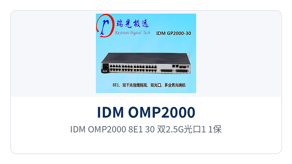
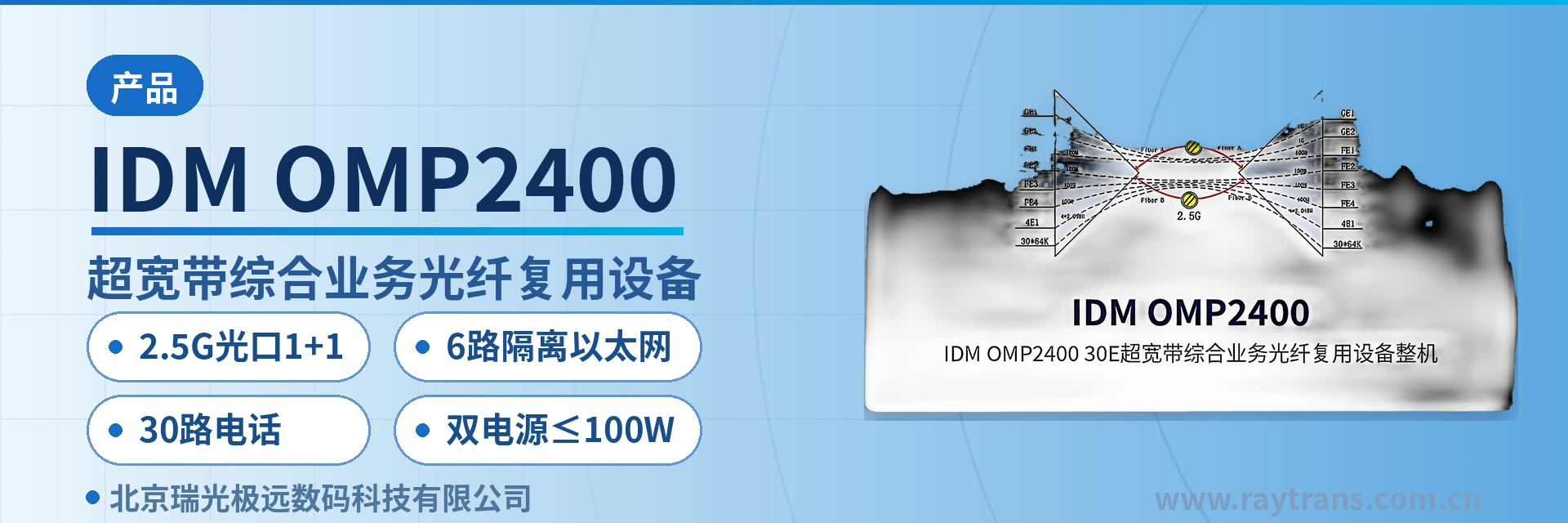
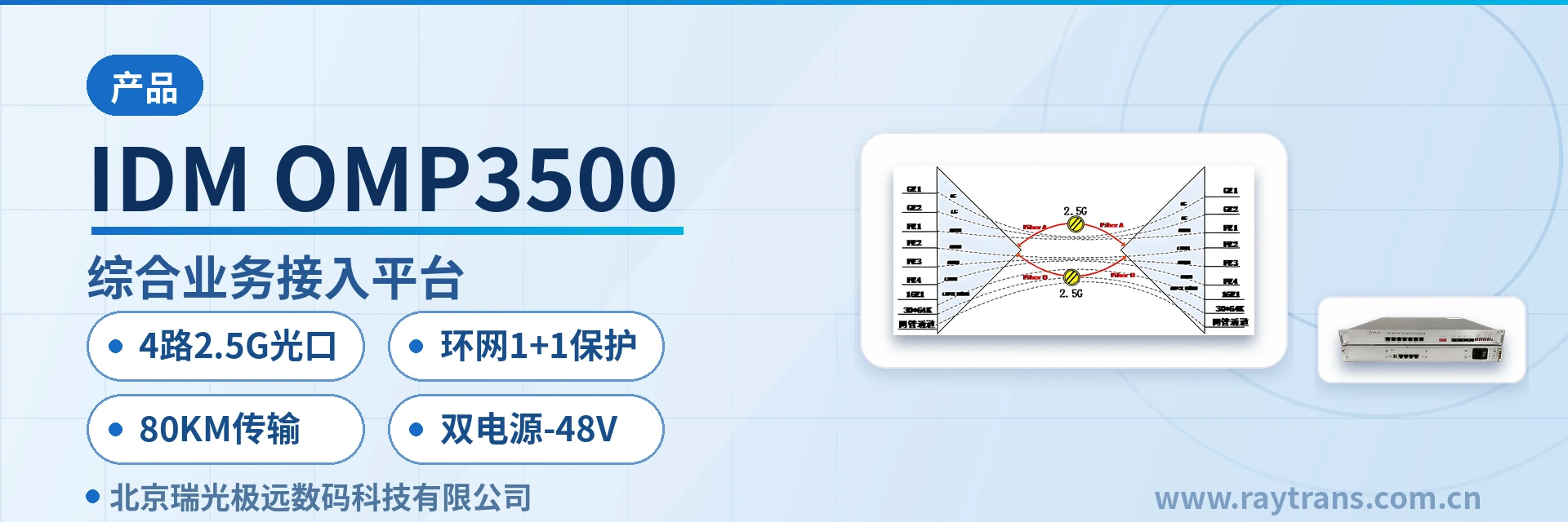
Figure 2: Point-to-point networking topology of the IDM OMP2000-8E1-30 with dual 2.5G optical port 1+1 protection, 8 E1 channels, and 2 isolated gigabit networks
Typical Application Scenarios
The IDM OMP2000-8E1-30 is mainly deployed point-to-point: one unit at the service site and one in the central equipment room, with the two ends directly connected over optical fiber. E1, isolated gigabit networks, and 64K services are restored at the central side and then connected back to the existing transmission and switching equipment; site expansion only requires additional interfaces, without laying new optical cables. As an integrated service access device, this model integrates E1 transparent transmission, isolated Ethernet, and 64K narrowband access capabilities in a single 1U unit, making it suitable for private network access points where optical fiber resources are tight and service types are diverse.
Electric Power Private Network: E1 Leased Lines and Isolated Data Backhauled over the Same Cable for Substations and Distribution Stations
Substations, distribution stations, and new energy stations simultaneously run dispatch automation, relay protection signals, and video surveillance. Most sites are unattended, and both equipment room space and the number of fiber cores are limited. The IDM OMP2000-8E1-30 packs 8 E1 channels, 2 physically isolated gigabit networks, and 30 64K interfaces into one 1U unit, so the station no longer needs a separate optical multiplexer for each service type.
Telecontrol and protection information runs over E1 channels, video surveillance and the office network each occupy one isolated gigabit port, and dispatching audio and low-speed telecontrol data run over 64K interfaces. The AC220V and DC-48V dual power supply corresponds to the two station power sources, AC and communications DC, and the -10℃~+50℃ operating temperature suits station equipment rooms without temperature control.
Rail Transit: Signal E1 and Surveillance Network Aggregation for Stations Along the Line and Section Equipment Rooms
Between stations and section equipment rooms of metros and conventional railways, train dispatching telephone, signal system E1 channels, and video surveillance data need to be transmitted, with station spacing of several kilometers and limited equipment room conditions. The IDM OMP2000-8E1-30 is deployed point by point according to site distribution; each station connects its services nearby and backhauls them to the central equipment room over the trunk optical fiber.
8E1 transparent transmission extends the existing E1 channels of the signal system as they are, so the station side can complete access without replacing existing equipment; the 2 independent gigabit networks separate surveillance and office into two networks, and inspecting one does not affect the other. 1+1 optical protection switches services to the spare fiber core for continued operation when the section optical cable is unexpectedly interrupted.
Military and Government Private Networks: Multi-Network Parallel Access for Temporary Command Posts and Classified Equipment Rooms
Field command posts, temporary training sites, and emergency communications sites usually have no ready-made transmission resources and need E1 leased lines, internal networks, and low-speed data paths established within a short time. The IDM OMP2000-8E1-30 uses a 19-inch 1U chassis, is easy to transport and rack-mount, and once the two ends are commissioned as a pair, all three service types run simultaneously over one optical fiber, making it one of the commonly used access models in military emergency communications vehicle solutions.
The 2 physically isolated gigabit Ethernet interfaces let the command network and the video backhaul network each use an independent channel, separating classified and non-classified services at the hardware level; the 64K interfaces can connect V.35, RS232/RS485/RS422, and other equipment, and dispatch terminals and low-speed data equipment connect through their original interfaces. The centralized configuration provides an SNMP network management interface, making it easy for the center to remotely check the status of remote stations. In government private network optical fiber communication solutions, this model can likewise serve as a multi-network parallel access node between classified equipment rooms and branch offices.
Conclusion
As an 8-channel E1 dual-gigabit isolated optical multiplexer, the IDM OMP2000-8E1-30 provides 1+1 optical protection through two 2.5Gbps SFP optical ports, 2 physically isolated independent gigabit Ethernet interfaces, and 8 E1 channels transparently transmitted per ITU-T G.703, 75 Ω, HDB3, and PCM30/31, plus 30 64K interfaces carrying voice and low-speed data. The unit combines the attributes of both optical multiplexing equipment and integrated service access device, completing unified access of E1, Ethernet, and narrowband services in a single 1U unit.
The device uses a 19-inch 1U chassis, with AC220V/DC-48V dual power supply, overall power consumption ≤150W, and an operating temperature of -10℃~+50℃. During selection, first count the number of E1 channels at the site, the number of Ethernet security domains, and the 64K service types, then calculate the link loss budget and confirm the power supply format, and the configurations at both ends can be aligned. Raytrans provides product showcase and technical support from selection calculation to two-end configuration alignment, making it easy for users to quickly determine the unit configuration according to the site service list.