
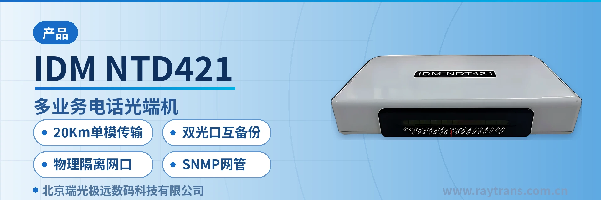
IDM NTD421 Multi-Service Telephone Optical Multiplexer
2 telephone channels, 2 groups of physically isolated Fast Ethernet ports, dual optical port mutual backup, single-fiber 20 km
The IDM NTD421 multi-service optical multiplexer provides a 250M optical interface, 2 telephone channels and 2 groups of physically isolated Fast Ethernet ports, where ports 1, 2, 3 and the fourth channel are physically isolated, and a 220V power supply. The IDM NTD421 multi-service optical multiplexer can be used in point-to-point applications with dual optical port mutual backup. It provides a standard SNMP network management interface.
IDM NTD421 dual optical port mutual backup telephone optical multiplexer is a multi-service optical multiplexer developed by Beijing Ruiguang Jiyuan Digital Technology Co., Ltd. (Raytrans). It is an optical multiplexer product for private network scenarios, used to carry 2 telephone channels and 2 groups of physically isolated Fast Ethernet services simultaneously over a single 250M optical fiber link, achieving integrated product showcase transmission of telephone and data. The device adopts FC single-mode optical interfaces, comes standard with a transmission distance of 20 Km, supports dual optical port mutual backup on the line side, and provides a standard SNMP network management interface.
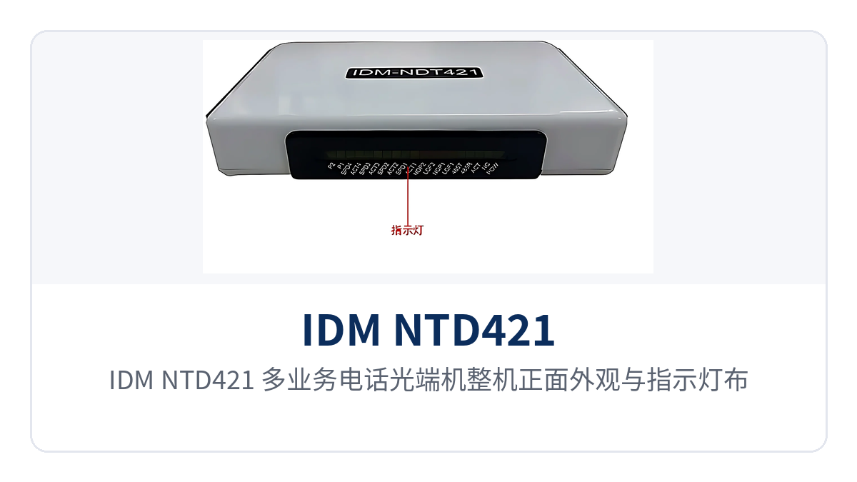
Figure 1: Front view and indicator LED layout of the IDM NTD421 multi-service telephone optical multiplexer
Key specifications at a glance: 250M optical interface · 20 Km single-mode transmission · 2 telephone channels and 2 groups of isolated Fast Ethernet ports · dual optical port mutual backup · physically isolated Ethernet ports · SNMP network management
As a multi-service optical multiplexer that combines telephone access with gigabit network optical multiplexer expansion capability, the device is deployed as a pair in point-to-point mode: one end connects to the telephones and service network on the site side, and the other end restores them in the equipment room or dispatch center, with a single optical fiber connecting the two. Telephone and Ethernet services each occupy an independent channel on the same link, so on site there is no need to lay separate cables for each service type, nor to change the wiring of existing telephones and dispatch consoles. The product is developed by the professional optical multiplexer manufacturer Raytrans and can be flexibly applied to scenarios such as government private network optical fiber communication solutions and military emergency communications vehicle solutions, providing private network users with stable and reliable product showcase and transmission assurance.
What kind of device is the dual optical port mutual backup telephone optical multiplexer?
The IDM NTD421 dual optical port mutual backup telephone optical multiplexer integrates telephone access, Ethernet access, and optical transmission into a single device; used in pairs at both ends, they form a complete service link. As a multi-service optical multiplexer for private network scenarios, the device provides FC single-mode optical interfaces, a receive/transmit rate of 250M/250M, and receive/transmit wavelengths of 1310nm/1550nm; on the user side it provides 2 telephone channels and 2 groups of physically isolated Fast Ethernet ports, and the unit supports both AC220V and DC-48V power supply. On this model, Raytrans integrates the access capability of a telephone optical multiplexer and the transmission capability of an optical multiplexer on the same platform, facilitating unified deployment and maintenance on the site side.
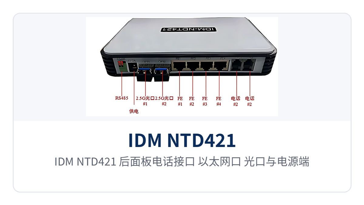
Figure 2: Rear panel layout of telephone interfaces, Ethernet ports, optical ports, and power supply terminals on the IDM NTD421
Inside the device, telephone services are first digitized in PCM mode and then sent over the optical fiber: the audio range is 300 Hz to 3400 Hz, ITU G.711 A-law compression is adopted, the loop current is 20 mA per channel, and the voice channel impedance is a three-element complex impedance of 200Ω+560Ω//0.1μF. Once digitized, the voice channels occupy fixed bandwidth and are transmitted in parallel with Ethernet services within the same optical channel.
The significance of this approach is that existing analog telephones and dispatch consoles need no modification and can be used as usual once connected to the voice channel interfaces; the Ethernet side follows the IEEE802.3 standard and supports full/half duplex and rate adaptive operation. The two service types each occupy an independent channel inside the device, so bursty telephone traffic will not squeeze the bandwidth of the Ethernet ports. For sites that require the Ethernet carrying capacity of a gigabit network optical multiplexer, the device provides channels for Ethernet services over the 250M optical link, and service bandwidth is calculated uniformly according to link capacity.
Summary table of functions and performance specifications
The device is designed around four categories of capability: telephone access, isolated Ethernet, optical port redundancy, and remote network management. Each function is listed in the table below for item-by-item comparison with on-site service requirements. The table also indicates the interface and configuration method corresponding to each capability, so that service types can be confirmed row by row during on-site checks.
| Function | Description |
|---|---|
| 250M optical interface transmission | Provides FC single-mode optical interfaces, receive/transmit rate 250M/250M, receive/transmit wavelength 1310nm/1550nm, standard transmission distance 20 Km |
| 2 telephone channels | Provides 2 telephone interfaces, audio range 300 Hz to 3400 Hz, ITU G.711 A-law compression, loop current 20 mA per channel |
| 2 groups of physically isolated Fast Ethernet ports | Ethernet ports are configured as 2 groups of physically isolated channels; the channels do not share forwarding resources, and service data is carried per channel |
| Dual optical port mutual backup | Two optical ports can be configured on the line side; when the primary optical fiber fails, services are continued over the backup optical fiber, with no change to terminal configuration on the service side |
| SNMP network management | Provides a standard SNMP network management interface, allowing device and link status to be viewed remotely from the network management center and reducing on-site inspection |
| Full/half duplex adaptive | Ethernet follows the IEEE802.3 standard and supports full/half duplex and 10M/100M/1000M rate adaptive operation |
| Replaceable optical module | The FC optical interfaces support replacement with long-distance optical modules, extending the standard 20 Km distance to cover more remote field private networks |
Technical specifications of optical ports and service interfaces
The following specifications cover optical interfaces, Ethernet interfaces, voice channel interfaces, power supply, and environmental conditions. The values are based on IDM NTD421 product documentation and are intended for networking design and equipment selection calculations. During selection, first determine the interface configuration according to service volume and transmission distance, then use the optical power specifications to calculate the link budget. As an optical multiplexer manufacturer, Raytrans provides complete optical power and interface specifications in its product documentation, making them directly usable by engineering parties for link calculations.
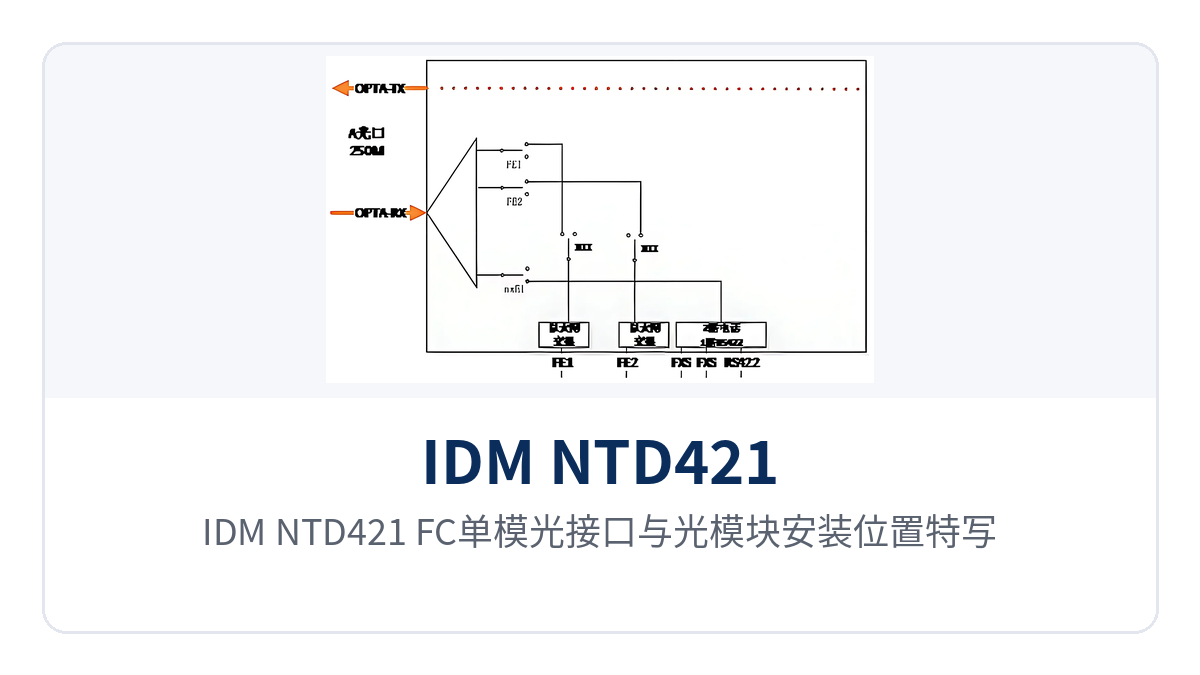
Figure 3: Close-up of the FC single-mode optical interfaces and optical module installation positions on the IDM NTD421
| Item | Parameter/Specification | Description/Applicable Conditions |
|---|---|---|
| Optical interface type | FC | Single-mode optical interfaces, optical modules supplied with the device |
| Fiber mode | Single-mode (multi-mode optional) | Selected according to line conditions and distance |
| Receive/transmit rate | 250M/250M | Shared by telephone and Ethernet services |
| Receive/transmit wavelength | 1310nm/1550nm | Used in pairs for receive and transmit |
| Transmit optical power | -12~-6dBm | Subject to the factory value of the selected optical module |
| Receiver sensitivity | Better than -18dBm | Lower limit of received optical power at the end of the link |
| Transmission distance | 20 Km, long-distance optical modules optional | Longer distances determined by the optical module and link budget |
| Ethernet interface | RJ-45 | 4 Ethernet ports configured as 2 groups of physically isolated channels |
| Ethernet rate | 10M/100M/1000M adaptive | Interface auto-negotiation; service bandwidth is constrained by the capacity of the 250M optical link |
| Ethernet protocol | Supports IEEE802.3 | Full/half duplex/adaptive |
| Telephone interface | 2 channels | Connects to analog terminals such as telephones and dispatch consoles |
| Audio range | 300 Hz to 3400 Hz | Standard telephone voice bandwidth |
| Voice channel compression | ITU G.711 A-law | 64 Kbps digital voice per channel |
| Voice channel impedance | Three-element complex impedance 200Ω+560Ω//0.1μF | Matches common telephones and exchange-side interfaces |
| Loop current | 20 mA/channel | Feeding capability of each voice channel |
| Network management interface | Standard SNMP | Connects to the network management center for unified monitoring |
| Power supply mode | AC220V/DC-48V | Selected according to site power supply conditions |
| Overall power consumption | ≤90W | Unit value including optical modules |
| Operating temperature | -10℃~+50℃ | Installed in equipment rooms and cabinets |
| Relative humidity | 0~95% (non-condensing) | For use in non-condensing environments |
| Dimensions | Subject to the documentation supplied with the product | Verify against cabinet space before installation |
How are services allocated between the 2 telephone channels and the physically isolated Fast Ethernet ports?
The allocation principle is to let telephones and data of different security levels each use independent channels, avoiding mutual interference between services. The telephone ports are all connected to dispatch telephones or user telephones, while the Ethernet ports are grouped by security domain, carrying external communications and internal production data separately. The grouping results must be recorded in the site wiring table to prevent services of different security domains from being connected to the same group of Ethernet ports during installation. In government private network optical fiber communication solutions, this security-domain grouping directly corresponds to the service isolation requirements of different government departments; in military emergency communications vehicle solutions, it facilitates rapid wiring deployment of in-vehicle telephones and data terminals.
- Telephone channel: the 2 voice channels connect to analog terminals such as dispatch consoles and telephones; audio 300 Hz to 3400 Hz, encoded with G.711 A-law before being sent over the optical fiber.
- Internal network ports: ports 1, 2, and 3 share one group of Fast Ethernet channels and can be divided into VLANs as needed, suitable for internal services such as office networks and video surveillance.
- Isolated network port: port 4 is an independent physically isolated channel, suitable for services such as production control and dispatch automation that must be strictly separated from external networks.
- Isolation method: the two groups of channels do not share bandwidth or forwarding resources; physical isolation is implemented inside the device and does not depend on VLAN partitioning of upper-layer devices.
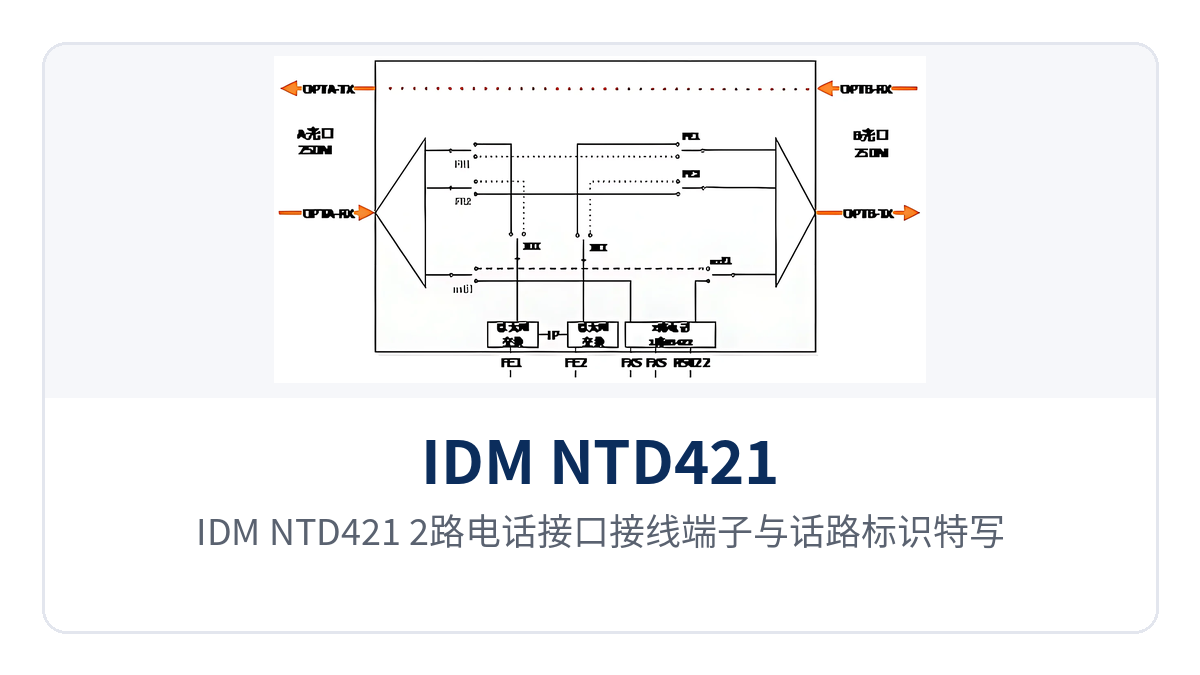
Figure 4: Close-up of the wiring terminals and voice channel markings of the 2 telephone interfaces on the IDM NTD421
With the above allocation, a single optical fiber carries both service types without crosstalk: even if centralized calling occurs on the voice channel side, production data on the Ethernet side is still forwarded over its own channel. For sites such as electric power and rail transit that have both dispatch voice and automation data, this allocation reduces the number of devices and the number of cables. The interface layout and channel grouping shown in the product showcase also make it easy to quickly verify port allocation against site service volume in government private network optical fiber communication solutions and military emergency communications vehicle solutions.
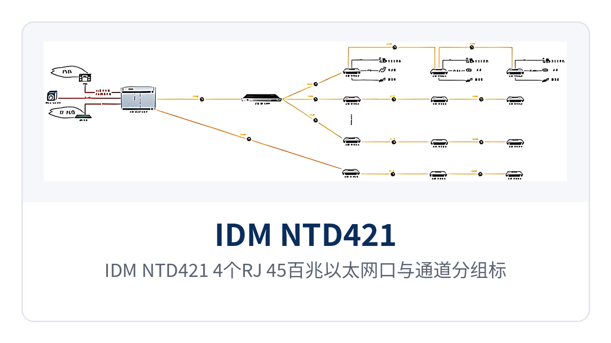
Figure 5: The 4 RJ-45 Fast Ethernet ports and channel grouping markings on the IDM NTD421
How do dual optical port mutual backup and telephone optical multiplexer SNMP network management work together?
Dual optical port mutual backup addresses single point of failure on the optical fiber link. The device is configured with two optical ports on the line side, one primary and one backup; when the primary optical fiber is interrupted or received optical power is insufficient, services are continued over the backup optical fiber, with no change required to service interfaces or terminal configuration at either end; on site, only two optical cables on different routes need to be prepared. As a professional optical multiplexer manufacturer, Raytrans clearly indicates the working mechanism of dual optical port mutual backup in its product showcase for easy verification during selection.
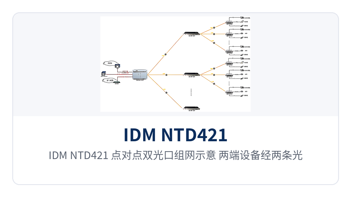
Figure 6: Point-to-point dual optical port networking diagram of the IDM NTD421, with devices at both ends interconnected via two optical fibers
SNMP network management brings link status to the network management center, so on-duty personnel can determine whether the device is online and whether the optical ports are normal without visiting the site. The device provides a standard SNMP network management interface and can connect to an existing NMS platform, incorporating optical port switchover and device alarms into the monitoring scope. For telephone optical multiplexers deployed in government private network optical fiber communication solutions, this capability is particularly useful.
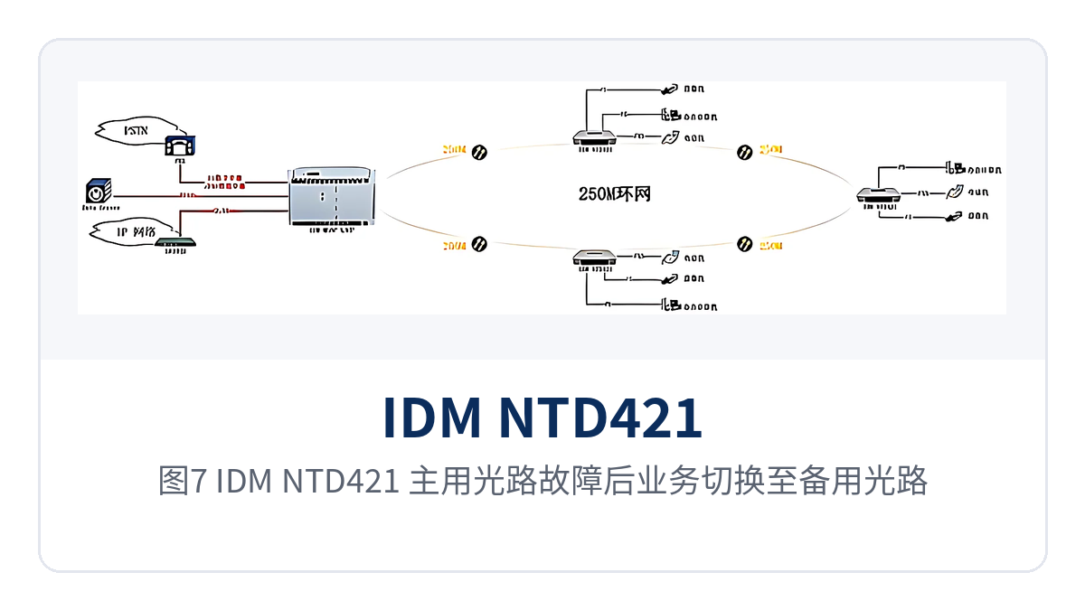
Figure 7: Link diagram of service switchover to the backup optical path after a primary optical path fault on the IDM NTD421
Used together, redundancy and network management shorten the fault handling path: optical port switchover ensures services are continued first, and network management alarms then indicate whether the problem lies in the optical fiber, the optical module, or the service interface. For unattended sites, this combination turns after-the-fact troubleshooting into status assessment that can be confirmed remotely.
What statuses can the SNMP network management of a telephone optical multiplexer monitor?
The routine items that can be monitored include device presence, optical port receive/transmit status, Ethernet and voice channel interface status, and power supply alarms. The specific alarm entries and MIB definitions that can be read are subject to the network management documentation provided by the manufacturer. Once these statuses are connected to the network management center, inspection can change from periodic on-site visits to remote viewing, and fault response time is shortened accordingly.
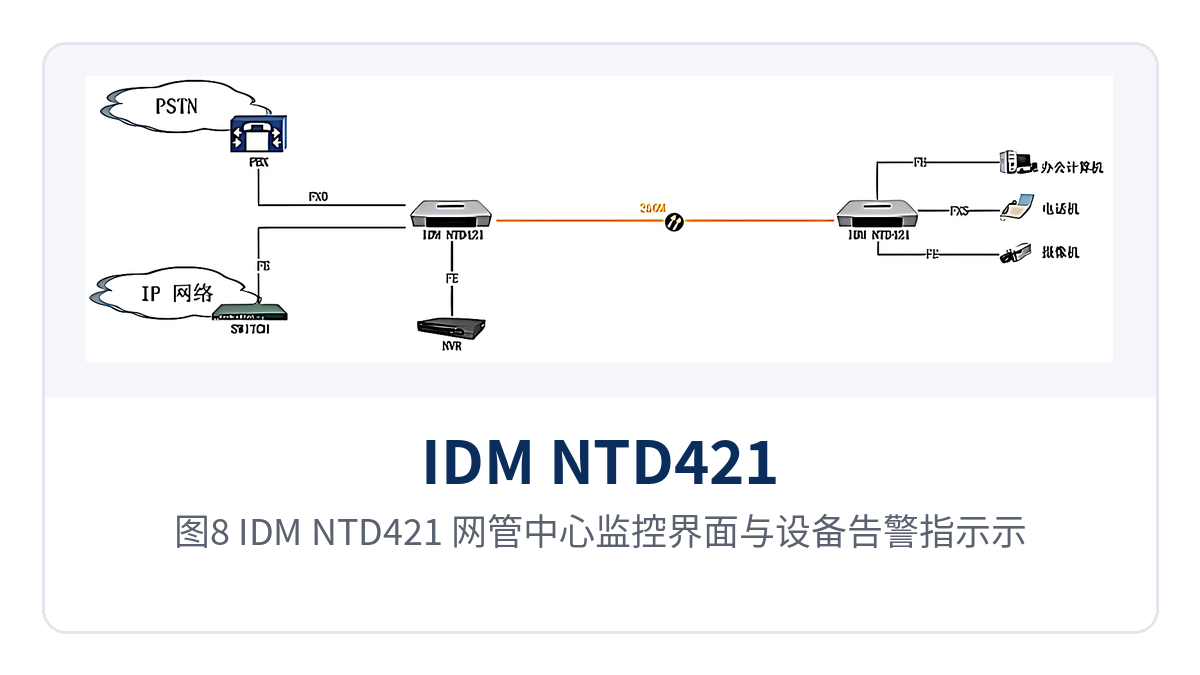
Figure 8: IDM NTD421 network management center monitoring interface and device alarm indication schematic
Can a 20Km single-mode telephone optical multiplexer transmit farther?
20Km is the standard transmission distance. The actual achievable distance is jointly determined by the optical module and the link loss; when a longer distance is required, simply replace the optical module with a long-distance one, and the unit itself and the service interfaces remain unchanged. During selection, use the transmit optical power of -12 to -6 dBm and the receiver sensitivity better than -18 dBm to calculate the link budget, then include optical fiber attenuation, splice points, and mating connectors in the calculation.
As a 250M optical port telephone optical multiplexer, the transmission capability of the IDM NTD421 is also affected by the optical fiber type and wavelength selection: for single-mode fiber, the per-kilometer attenuation is taken according to the selected wavelength, and modules at the two wavelengths of 1310nm and 1550nm must be used in paired configuration. In engineering practice, a margin of several dB is generally reserved beyond the calculation result, and the specific value is determined according to the project design requirements.
How is the link budget calculated for a 20Km single-mode telephone optical multiplexer?
The link budget calculation is listed step by step in four steps, to avoid ordering solely based on the nominal 20Km. The value of each step is taken from the selected optical module and the actual line measurement data; missing any one item may overestimate the usable distance, and after commissioning, insufficient received optical power will require rework and module replacement at a higher cost.
- Transmit optical power: take the factory value of the selected optical module, in the range of -12 to -6 dBm.
- Receiver sensitivity: use better than -18 dBm as the lower limit of received optical power at the end of the link.
- Optical fiber attenuation: take the per-kilometer attenuation according to the wavelength and optical fiber type, and multiply by the line length.
- Engineering margin: reserve margin for splice points, connectors, and long-term aging, with the value determined according to the project design requirements.
Typical application scenarios
Electric power private network: dispatch telephone and in-station data between substations and dispatch offices
Between a substation and a dispatch office, there are usually two types of services at the same time: dispatch telephone and in-station data. The IDM NTD421 is installed at both ends, delivering 2 voice channels and two groups of isolated network ports over one single-mode fiber; the telephone runs over the voice channel, and the in-station automation data runs over the independent physically isolated network port, so the two types of services do not mix. There is no need to lay separate cables for telephone and data between stations, and the existing dispatch console and telephone keep their original usage.
When line conditions permit, connect the dual optical ports to two optical cables on different routes. When the primary link is abnormal, the backup link takes over, so dispatch voice will not be completely lost due to a single optical cable interruption. For unattended substations, SNMP network management sends device and optical port status to the network management center on the dispatch side, and both inspection and fault diagnosis can be completed remotely.
Rail transit communication: official telephone and monitoring data access between stations and depots
Stations, depots, and trackside sites along the line are scattered, and official telephone and monitoring data often run over different cables and are maintained by different disciplines. On the station side, the IDM NTD421 multiplexes voice channels and monitoring data onto one optical fiber for backhaul, with network ports grouped by security domain, so the monitoring network and the office network each occupy one group of channels. Sections with tight section optical cable resources benefit especially, and new services no longer need to apply for fiber cores.
After the inter-station link adopts dual optical port mutual backup, a single optical cable failure affects only one route, and services are taken over by the other optical path; on the network management side, the device and optical port status at both ends can be seen at the same time, and fault section diagnosis no longer relies on station-by-station telephone confirmation. The optical port status at both ends is aligned on the same network management interface, making it easy to determine whether it is a single-segment fiber break or a bidirectional interruption.
Military/government private network: telephone and intranet data extension to remote ends and duty posts
Remote duty posts, storage areas, and duty points usually have limited maintenance resources and simple equipment room conditions, and place higher requirements on the power supply adaptability and remote manageability of the equipment. The IDM NTD421 supports two power supply modes, AC220V and DC-48V, with overall power consumption ≤90W and an operating temperature of -10℃ to +50℃, and can be installed in a temperature-controlled standard cabinet. In the military emergency communications vehicle solution, this wide-temperature, wide-range multi-service optical multiplexer can be rapidly deployed in a vehicle-mounted cabinet, enabling immediate extension of telephone and intranet data.
On the service side, 2 telephone lines and intranet data are connected separately, and the physically isolated network ports let intranet data and telephone voice each run over an independent channel; with dual optical port mutual backup combined with SNMP network management, link redundancy and status monitoring both rest on the device side, reducing manual duty at remote ends. Raytrans provides corresponding selection recommendations for gigabit network optical multiplexers and multi-service optical multiplexers for both the government private network optical fiber communication solution and the military emergency communications vehicle solution, making it easy to match port configuration according to service volume.
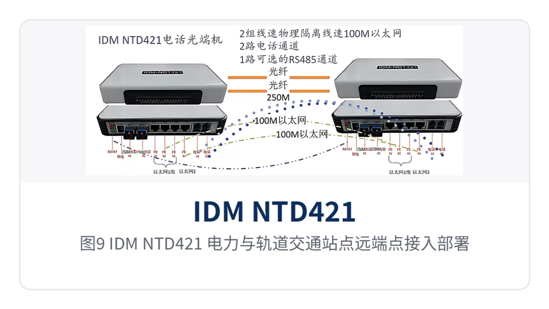
Figure 9: IDM NTD421 electric power and rail transit site remote end access deployment schematic
Conclusion
The IDM NTD421 dual optical port mutual backup telephone optical multiplexer brings 2 telephone lines and two groups of physically isolated Fast Ethernet ports into one 250M single-mode fiber, comes standard with 20Km and can be fitted with a long-distance optical module, and its dual optical port mutual backup and SNMP network management put both redundancy and manageability of the remote link in place. Raytrans offers a complete optical multiplexer model spectrum in its product showcase, covering categories such as telephone optical multiplexers, multi-service optical multiplexers, and gigabit network optical multiplexers, which can be flexibly selected according to project requirements.
For remote stations of electric power private networks, rail transit communication, and military and government private networks, the value of this type of equipment lies in fewer cables laid and fewer on-site visits: telephone and data are carried over separate channels, the link has a backup optical port for take-over, and device status can be viewed at the network management center. The equipment is deployed in the standard cabinet installation method; on the site side, only power supply and optical fiber patch cords need to be prepared, and the commissioning workload is concentrated on fiber splicing and service cutover at both ends.


