
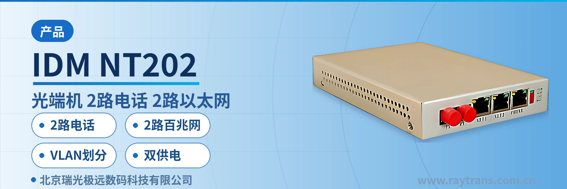
IDM-NT202 Telephone Optical Multiplexer
A Pair of Enclosures Delivers 2 Telephone Channels and 2 Ethernet Channels at Once, One Fiber Saves a Whole Set of Transmission Equipment
The 2-channel telephone optical multiplexer adopts a desktop type chassis structure design and provides 2 telephone interfaces and 2 groups of shared 100M Ethernet channels through 1 optical fiber channel, and the 2 Ethernet interfaces can be partitioned into VLANs at will; the IDM-NT202 multi-service optical multiplexer can be widely used for public telephone network access and dedicated line information transmission in sectors such as telecom data services, electric power, banking, public security, the military, schools and expressways.
As a typical multi-service optical multiplexer, the device extends voice and data services to remote user areas, can replace remote small offices to complete cross-boundary line extension, and is also used for dedicated line access in sectors such as electric power, banking, public security, the military, schools and expressways. The unit can work once it is placed on the workbench in the wiring closet or on the tray of a small cabinet, and it occupies no 19-inch rack space; when a site is commissioned, only the service cables and one fiber patch cord need to be connected. The product is also often used in government private network optical fiber communication solutions and military emergency communications vehicle solutions, as a small-capacity access device recommended by the optical multiplexer manufacturer.
Key specifications at a glance*: 2 telephone channels · 2 Fast Ethernet channels · VLAN partitioning · dual power supply · sensitivity better than -36dBm · shared 100M Ethernet · 15W · desktop type 172×110×25mm
**## What Kind of Device Is a Single Fiber 2-Channel Telephone and 2-Channel Ethernet Optical Multiplexer?**This is a point-to-point fiber access device used in pairs: one end is installed on the switching office side or in the central equipment room, and the other end is placed at a remote station. The two devices are connected by one optical fiber, and voice and Ethernet services are transmitted bidirectionally over the optical path. The remote station no longer needs separate transmission devices for telephones and the network: a pair of enclosures delivers both types of service at the same time, which is also a common form of small optical multiplexer in the Raytrans product showcase.
All service ports appear in pairs on the same enclosure, and the number of interfaces at the station side matches that at the equipment room side, so installation crews only need to check them against the site list. The device uses a desktop type structure by default and requires no additional chassis, plug-in board or fan unit, making it suitable for sites with few access points that are scattered in location.
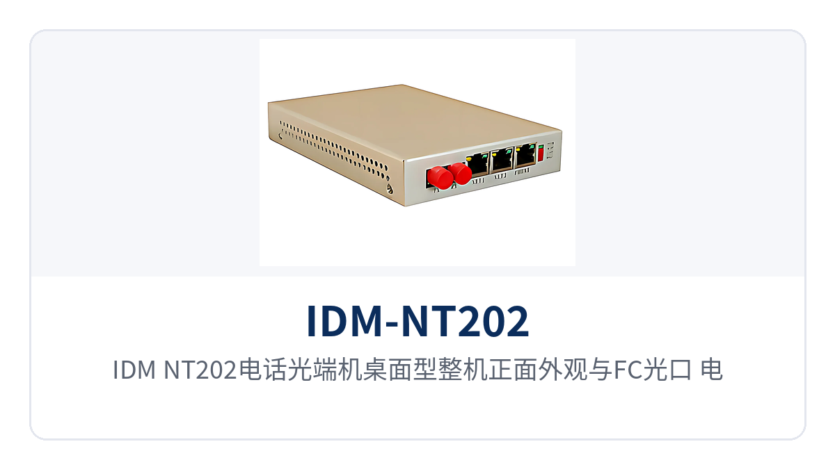
Figure 1: Overall appearance of the unit, the IDM-NT202 desktop type telephone optical multiplexer, with a close-up of the FC optical port, telephone ports, Ethernet ports and indicator LEDs*
Voice is compressed inside the device into 64Kbps digital voice channels in A-law as specified in ITU G.711, with an audio range of 300Hz to 3400Hz, and the loop current of each channel is 25mA. G.711 is the voice coding standard specified in the ITU-T recommendations, and A-law is commonly used in domestic telephone networks, so telephones and switching equipment can interoperate directly without an additional conversion device.
On the Ethernet side, 2 groups of shared 100M channels are provided; the two ports share one 100M bandwidth and can be connected to the office network switch and video terminals respectively. Voice and Ethernet each occupy an independent channel on one optical fiber, so the fixed bandwidth used by telephones is not affected by burst traffic on the Ethernet side, and call quality is not squeezed when large files are downloaded from the network side.
The bandwidth of the shared channel is dynamically allocated between the two Ethernet ports: when one port is idle, the other can use the full 100M, and when both ports carry traffic, the bandwidth is divided according to actual demand. For the scenario common at remote stations where office Internet access and video backhaul coexist, this allocation method saves bandwidth compared with fixed partitioning, and it also reflects the practical value of a multi-service optical multiplexer in bandwidth scheduling.
Core Functions and Specifications at a Glance
The functions of the IDM-NT202 are configured in three categories, namely voice, Ethernet and optical fiber transmission. Each capability and its corresponding interface are listed in the table below, for item-by-item checking against the site list. The number of interfaces, the optical port type and the power supply mode are confirmed once at the time of ordering, and on-site installation follows the delivered configuration.
| Function | Description |
| --- | --- |
|| 2 Telephone Channels | Provides 2 ordinary telephone interfaces with an audio range of 300Hz to 3400Hz, compressed in A-law as specified in ITU G.711, with a loop current of 25mA per channel, and can be connected to telephones or switching equipment ||| 2 Shared 100M Ethernet Channels | Provides 2 groups of shared 100M Ethernet channels; the two ports share one 100M bandwidth and can be connected to switches, acquisition terminals or network cameras ||
| --- | --- |
|| VLAN Partitioning | The 2 Ethernet interfaces can be partitioned into VLANs at will, so that the office network, video network and management network are isolated on the same optical path and broadcast packets do not spread to each other ||| Single Fiber Multi-Service Carrying | 2 telephone channels and 2 Ethernet channels are multiplexed onto one optical fiber channel, so a site occupies only one fiber core and saves another pair of optical multiplexers and the associated optical fiber cable ||
|| Desktop Type All-in-One Enclosure | Voice, Ethernet and optical transmission are integrated into a 172×110×25mm desktop enclosure, which can be placed on a workbench or a cabinet tray and takes up no rack space ||| Dual Power Supply Modes | Two power supply modes, DC5 or AC 220V, are available, so both AC power from the equipment room and DC power at a station can be connected directly ||
|| Item | Parameter/Specification | Description/Applicable Conditions ||| --- | --- | --- ||
|| Optical interface type | FC (SC and others can be customized) | Optional according to the on-site optical cable termination method ||| Fiber mode | Single-mode (multi-mode optional) | Single-mode is the standard configuration; for short-distance multi-mode scenarios, specify at the time of ordering ||
|| Optical fiber rate | 155bps±50ppm | Value as marked in the original text, subject to the manufacturer's technical data ||| Wavelength | 1310nm | 1310nm window for single-mode ||
|| Transmit optical power | -2 to -11dBm | Together with the receive-end sensitivity, determines the optical power budget ||| Receiver sensitivity | Better than -36dBm | The link can still be maintained in weak-light and degraded fiber environments ||
|| Audio range | 300Hz to 3400Hz | Consistent with the voice band of the public telephone network ||| Impedance | Three-element complex impedance 200Ω+560Ω//0.1μF | Matches the interfaces of telephones and switching equipment ||| Compression | ITU G.711 A-law | 64Kbps per voice channel ||
| --- | --- | --- |
|| Loop current | 25mA per channel | Feeding capability for the telephone set ||| Power supply mode | DC5 or AC 220V | Dual power supply optional, selected according to the on-site power source ||| Overall power consumption | 15W | Power consumption per station, for long-term online operation ||
|| Operating temperature | 0℃ to +50℃ | Indoor wiring closet and cabinet environment ||| Humidity | 95% non-condensing | For use in non-condensing environments ||| Enclosure dimensions | 172×110×25 (mm) | Desktop type, length × depth × height ||
|## How Does VLAN Partitioning Isolate Telephone and Data Services| 155bps±50ppm |The 2 Ethernet interfaces can be partitioned into VLANs at will, placing the office network, video network and device management network in different VLANs, so that broadcast packets of the three network segments do not spread to each other, and multiple services running on one shared 100M channel do not interfere at the frame level. Telephone services use independent fixed time slots and do not participate in Ethernet VLAN partitioning, so voice and data are completely separated logically.|
|For toll stations, substations or barracks gate posts where only one optical fiber is available, this partitioning allows one set of transmission equipment to meet both the dedicated telephone line and intranet access requirements. VLANs can be implemented by port-based partitioning, with no need to add a managed switch at the remote end, and the configuration items correspond one to one with the site service table.| 1310nm |When VLAN tags need to be passed through transparently across devices, configure a trunk port on the switch side in IEEE 802.1Q format; the optical multiplexer forwards Ethernet frames transparently without modifying the tags. During on-site commissioning, first verify communication within the same VLAN, then open cross-network-segment access segment by segment, so that the troubleshooting scope always stays within one network segment.|
|## What Keeps the Link Stable in Weak-Light Environments| -2~-11dBm |A receiver sensitivity better than -36dBm is the key specification that allows this telephone optical multiplexer to keep working over degraded optical fiber. The transmit optical power is -2 to -11dBm, leaving an optical power margin of about 34dB against the -36dBm receive threshold, so sites with many splice points, aged patch cords or longer link distances still have margin to use.|
|In engineering practice this margin is treated as a budget to be allocated: the attenuation per kilometer of optical fiber is taken from the optical cable manufacturer's parameters, each splice point and each mating connector is counted as one segment of loss, and only what remains after these deductions is left for aging and maintenance. When the received optical power of a link approaches -36dBm, first clean and re-measure the connectors, then consider replacing the optical module with one of higher transmit optical power.|## Typical Application Scenarios|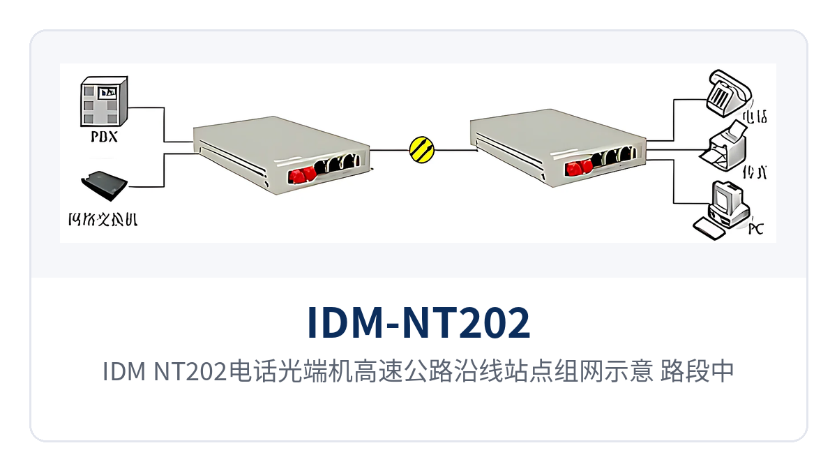 |
|Figure 2: Networking diagram of the IDM-NT202 telephone optical multiplexer at sites along an expressway, with the section central equipment room and the remote toll station interconnected by one optical fiber*| 300Hz~3400Hz |### Telephone and Network Access at Sites Along an Expressway|
|Toll stations, service areas and monitoring field devices are distributed along dozens of kilometers of a road section, the optical fiber along the route is laid uniformly by the electromechanical works, and the number of available fiber cores at a single point is limited. At each site, the IDM-NT202 provides 2 telephone channels and 2 Fast Ethernet ports over one optical fiber at the same time, so toll duty telephones, lane voice and monitoring data run on the same link.|At site commissioning, telephones are connected to the telephone ports and cameras or switches to the Ethernet ports, and the same model is configured in pairs at the equipment room side. VLANs separate the monitoring network from the office network; the section center locates abnormal sites by VLAN, and the on-site crew only checks by port without logging in to each device one by one.|### Service Access at Substations and Distribution Rooms of the Power Private Network|
|Substations and distribution rooms are numerous and scattered in location, and dispatch telephones and electricity consumption data collection usually run on different channels. The 2 telephone channels connect the dispatch console and the duty telephones in the station, the 2 Fast Ethernet ports connect the collection terminals and video inspection equipment, and one optical fiber delivers both types of service to the power supply station.|The device consumes 15W and can be powered by either DC5 or AC 220V, so the DC distribution panel or an AC socket in the station can be used as needed. The desktop enclosure can be fixed directly on the tray of a distribution cabinet, so a retrofit project needs neither additional rack space nor a separate pair of optical multiplexers for telephones and data.|### Fixed Site Access for Public Security and Military Private Networks|
|Telephones and intranet terminals at duty posts, checkpoints and barracks gate posts need to be connected to the superior equipment room, and private networks have clear requirements for service isolation. The 2 Ethernet ports carry intranet office and video backhaul on separate VLANs, telephones use independent time slots, and the three types of service do not interfere with each other on the same optical fiber. As an optical multiplexer manufacturer, Raytrans can provide access devices configured in pairs and selection support for such government private network optical fiber communication solutions and military emergency communications vehicle solutions.|The optical port is FC by default and can be customized to SC according to the on-site termination method, so as to match the existing optical cable cross-connect cabinet. The design with a receiver sensitivity better than -36dBm allows sites that reuse old optical cable to be commissioned even when splice loss is relatively high, eliminating the need to lay new cable for a degraded link.|## How Installation and Wiring Are Carried Out|
|The two 2-channel telephone optical multiplexers are used in pairs, and the wiring sequence is the same for the equipment room side and the station side. Complete the wiring and checks item by item in the following four steps on site, which saves more time than powering up first and troubleshooting afterwards; sign the record sheet after each step, and the same numbering can be used for later capacity expansion.|Optical path: connect one optical fiber to the optical ports at both ends, tighten the FC connectors fully, control the bend radius as required by the optical cable manufacturer, and label both ends of the patch cord.|Telephone: connect the 2 telephone channels to telephones or switching equipment; check the wire sequence against the wiring table first, then power up and test dialing and caller ID.|
|Ethernet: connect the 2 shared 100M ports to switches or terminals, partition VLANs according to the service table, and first ping each other within the same VLAN to confirm connectivity.| 15W |Power supply: select DC5 or AC 220V according to the on-site power source; after powering up, check the panel indicator LEDs and then re-test each service item by item.|
|After wiring is complete, tick off the items one by one against the site service table, and record telephone audio, Ethernet packet loss and the received optical power of the optical path together to form the initial baseline for the site. When an anomaly occurs later, comparing it with the baseline allows a quick judgment of whether the optical path has degraded or the configuration on the service side has changed. This procedure also applies to the on-site delivery of multi-service optical multiplexers, and the wiring guide provided by Raytrans in its product showcase can serve as a reference template.| 0℃~+50℃ |The IDM-NT202 is a single fiber 2-channel telephone and 2-channel Ethernet optical multiplexer developed by Beijing Ruiguang Jiyuan Digital Technology Co., Ltd., and it is one of the desktop type optical multiplexers in the product showcase of the Raytrans brand under Ruiguang Jiyuan. The device adopts a desktop type chassis structure and provides 2 telephone interfaces and 2 groups of shared 100M Ethernet channels at the same time through one optical fiber channel, for public telephone network access and dedicated line information transmission.|
|As a typical multi-service optical multiplexer, the device extends voice and data services to remote user areas, can replace remote small offices to complete cross-boundary line extension, and is also used for dedicated line access in sectors such as electric power, banking, public security, the military, schools and expressways. The unit can work once it is placed on the workbench in the wiring closet or on the tray of a small cabinet, and it occupies no 19-inch rack space; when a site is commissioned, only the service cables and one fiber patch cord need to be connected. The product is also often used in government private network optical fiber communication solutions and military emergency communications vehicle solutions, as a small-capacity access device recommended by the optical multiplexer manufacturer.|Key specifications at a glance|: 2 telephone channels · 2 Fast Ethernet channels · VLAN partitioning · dual power supply · sensitivity better than -36dBm · shared 100M Ethernet · 15W · desktop type 172×110×25mm|
|What Kind of Device Is a Single Fiber 2-Channel Telephone and 2-Channel Ethernet Optical Multiplexer?| 172×110×25(mm) |This is a point-to-point fiber access device used in pairs: one end is installed on the switching office side or in the central equipment room, and the other end is placed at a remote station. The two devices are connected by one optical fiber, and voice and Ethernet services are transmitted bidirectionally over the optical path. The remote station no longer needs separate transmission devices for telephones and the network: a pair of enclosures delivers both types of service at the same time, which is also a common form of small optical multiplexer in the Raytrans product showcase.|
All service ports appear in pairs on the same enclosure, and the number of interfaces at the station side matches that at the equipment room side, so installation crews only need to check them against the site list. The device uses a desktop type structure by default and requires no additional chassis, plug-in board or fan unit, making it suitable for sites with few access points that are scattered in location.
Figure 1: Overall appearance of the unit, the IDM-NT202 desktop type telephone optical multiplexer, with a close-up of the FC optical port, telephone ports, Ethernet ports and indicator LEDs
Figure 1: Overall appearance of the unit, the IDM-NT202 desktop type telephone optical multiplexer, with a close-up of the FC optical port, telephone ports, Ethernet ports and indicator LEDs
How Does One Optical Fiber Carry 2 Telephone Channels and 2 Ethernet Channels at the Same Time
Voice is compressed inside the device into 64Kbps digital voice channels in A-law as specified in ITU G.711, with an audio range of 300Hz to 3400Hz, and the loop current of each channel is 25mA. G.711 is the voice coding standard specified in the ITU-T recommendations, and A-law is commonly used in domestic telephone networks, so telephones and switching equipment can interoperate directly without an additional conversion device.
On the Ethernet side, 2 groups of shared 100M channels are provided; the two ports share one 100M bandwidth and can be connected to the office network switch and video terminals respectively. Voice and Ethernet each occupy an independent channel on one optical fiber, so the fixed bandwidth used by telephones is not affected by burst traffic on the Ethernet side, and call quality is not squeezed when large files are downloaded from the network side.
The bandwidth of the shared channel is dynamically allocated between the two Ethernet ports: when one port is idle, the other can use the full 100M, and when both ports carry traffic, the bandwidth is divided according to actual demand. For the scenario common at remote stations where office Internet access and video backhaul coexist, this allocation method saves bandwidth compared with fixed partitioning, and it also reflects the practical value of a multi-service optical multiplexer in bandwidth scheduling.
Core Functions and Specifications at a Glance
Function
Description
2 Telephone Channels
Provides 2 ordinary telephone interfaces with an audio range of 300Hz to 3400Hz, compressed in A-law as specified in ITU G.711, with a loop current of 25mA per channel, and can be connected to telephones or switching equipment
2 Shared 100M Ethernet Channels
Provides 2 groups of shared 100M Ethernet channels; the two ports share one 100M bandwidth and can be connected to switches, acquisition terminals or network cameras
VLAN Partitioning
The 2 Ethernet interfaces can be partitioned into VLANs at will, so that the office network, video network and management network are isolated on the same optical path and broadcast packets do not spread to each other
Single Fiber Multi-Service Carrying
2 telephone channels and 2 Ethernet channels are multiplexed onto one optical fiber channel, so a site occupies only one fiber core and saves another pair of optical multiplexers and the associated optical fiber cable
Desktop Type All-in-One Enclosure
Voice, Ethernet and optical transmission are integrated into a 172×110×25mm desktop enclosure, which can be placed on a workbench or a cabinet tray and takes up no rack space
- Dual Power Supply Modes
- Two power supply modes, DC5 or AC 220V, are available, so both AC power from the equipment room and DC power at a station can be connected directly
- Item
- Parameter/Specification
Description/Applicable Conditions


