
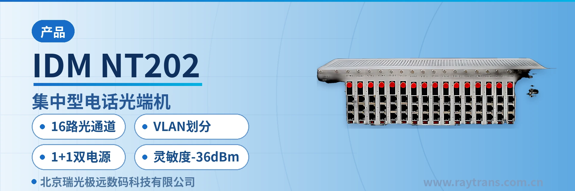
IDM-NT202 Centralized Telephone Optical Multiplexer
16 optical channels in a 3U chassis, telephone and Ethernet multiplexed over the same fiber, dual power supply 1+1 mutual backup
The IDM-NT202 multi-service optical multiplexer adopts a 19-inch 3U card-based chassis structural design; provides 16 dual-fiber (single-fiber) optical channels; the IDM-NT202 multi-service optical multiplexer provides 2 ordinary telephone interfaces with caller ID and 2 groups of shared 100M Ethernet channels, and the 2 Ethernet interfaces can be partitioned into VLANs arbitrarily; features comprehensive alarm indication; dual power cards supply power with 1+1 mutual backup;
The IDM-NT202 16-channel optical channel centralized telephone optical multiplexer is a centralized multi-service optical fiber access device developed by Beijing Ruiguang Jiyuan Digital Technology Co., Ltd. It uses a 19-inch 3U card-based chassis and multiplexes telephone and Ethernet services onto the same optical fiber for transmission, serving as a typical product showcase from an optical multiplexer manufacturer for multi-site access scenarios. A standalone unit provides 16 optical channels (dual-fiber or single-fiber), together with 2 caller ID telephone interfaces and 2 groups of shared 100M Ethernet channels. It is used for centralized multi-site access in electric power, rail transit, and military and government private networks, and can also serve as an access-layer optical multiplexer in government private network optical fiber communication solutions and military emergency communications vehicle solutions.
Key Specifications at a Glance: 16 optical channels · 2 telephone interfaces (caller ID) · 2 groups of shared 100M Ethernet · VLAN partitioning · 1+1 dual power supply · sensitivity -36 dBm
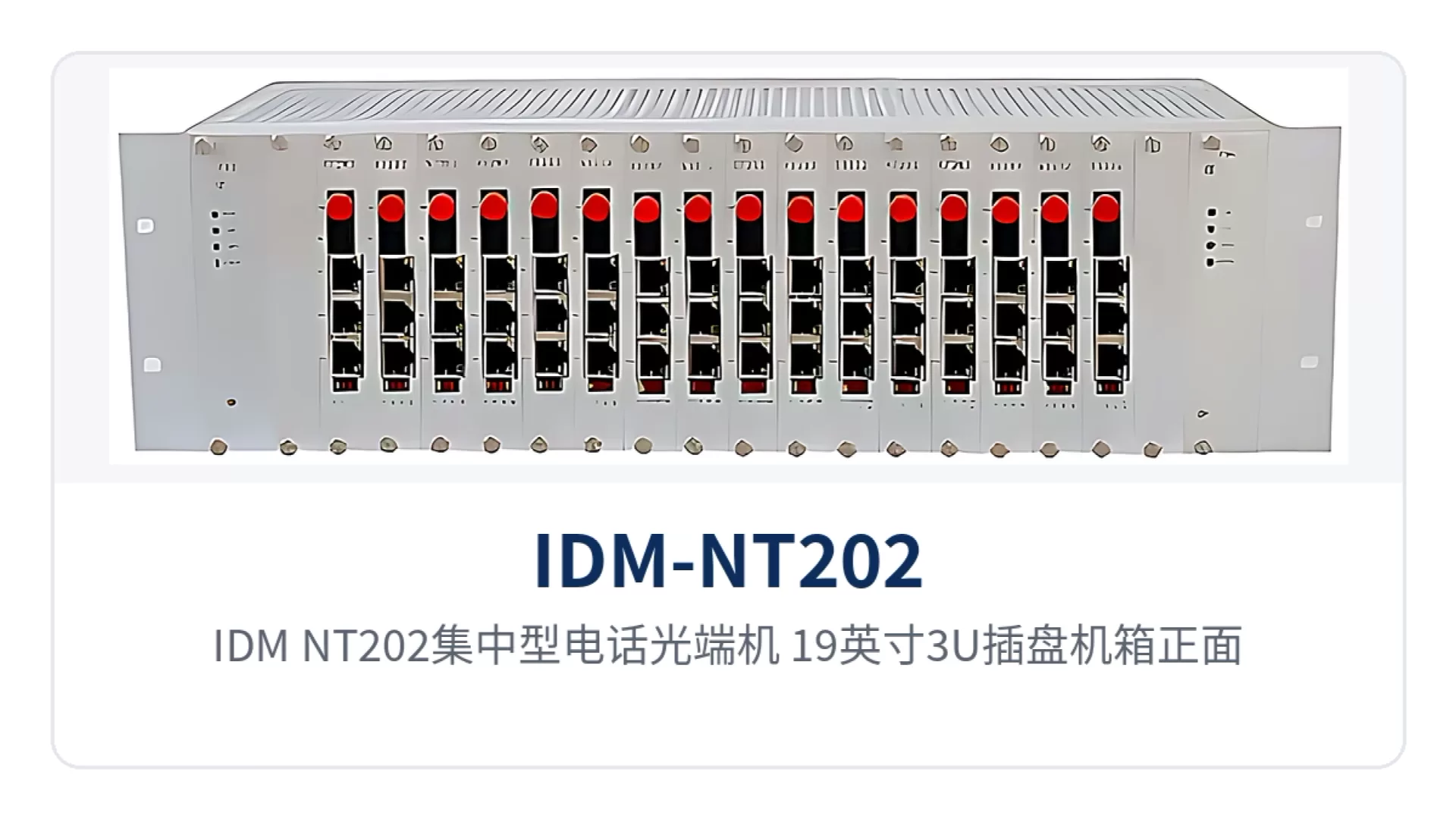
Figure 1: IDM-NT202 centralized telephone optical multiplexer, front view of the 19-inch 3U card-based chassis, close-up of optical ports and alarm indicator LEDs
What kind of device is the 16-channel optical channel centralized telephone optical multiplexer?
A centralized telephone optical multiplexer is an optical transmission device installed on the equipment room side that distributes voice and data services to multiple remote stations. Voice is compressed into 64 Kbps digital voice channels according to ITU G.711 A-law, with an audio range of 300 Hz to 3400 Hz; Ethernet is accessed at 10/100Base-T according to IEEE 802.3 with adaptive full/half duplex. The 16-channel optical channel centralized telephone optical multiplexer consolidates 16 optical ports into a single 3U chassis, so termination is completed once in the equipment room. As a professional optical multiplexer manufacturer, Raytrans provides complete selection references for centralized telephone optical multiplexers in this type of product showcase.
How does a single 3U chassis support 16 remote stations?
The direct benefit of centralized access is savings in equipment room space and optical fiber resources. One 19-inch 3U device replaces the stacking of multiple standalone chassis, optical cables are terminated centrally on the equipment room side, and as the number of sites grows, optical channels can be added card by card without replacing the entire unit.
The card-based structure inside the chassis and the way optical channels are allocated determine the specific practices for on-site capacity expansion, site mapping, and routine maintenance. The following four items are settled one by one during cabinet installation and later capacity expansion, so that cabling and numbering are finalized in one pass and no re-organization is needed when sites are added later.
- Number of optical ports: 16 optical channels per unit; dual-fiber and single-fiber models are selected according to existing optical fiber resources.
- Capacity expansion: optical channels are added card by card as services grow, and card slots are allocated according to the actual configuration.
- Centralized termination: the optical fibers of 16 sites are spliced and terminated once on the equipment room side, and cabinet cabling maps to sites by optical port number.
- Alarm observation: panel alarm indications reflect optical path and service status in a centralized way, so abnormalities can be found during equipment room inspection.
For multi-site projects, the value of the centralized type lies not only in the device itself but also in three things: the cabinet, the cabling, and maintenance. Once termination is unified on the equipment room side, fault diagnosis for remote stations can be pre-screened at the central equipment room, and on site it is enough to check sites by optical port number.
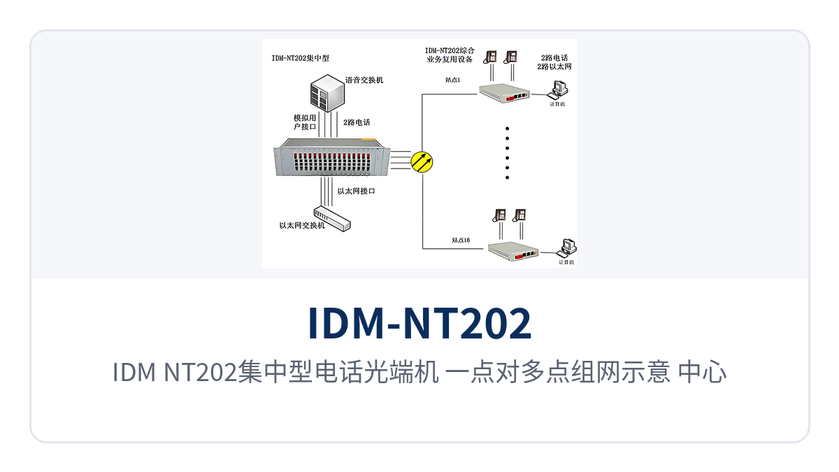
Figure 2: IDM-NT202 centralized telephone optical multiplexer, point-to-multipoint networking diagram, 16 optical channels from the central equipment room to multiple remote stations
How are telephone and Ethernet services carried over the same optical fiber?
Telephone and Ethernet each occupy an independent channel on the same optical fiber and do not interfere with one another, which is the prerequisite for a centralized device to carry multiple services over one cable. On the telephone side, voice is compressed into 64 Kbps digital voice channels according to ITU G.711 A-law; on the Ethernet side, access is adaptive at 10/100Base-T according to IEEE 802.3. The two types of services are multiplexed over optical channels and restored at the opposite end.
- Telephone interfaces: 2 ordinary telephone interfaces with caller ID, audio range 300 Hz to 3400 Hz, loop current 25 mA per channel.
- Ethernet interfaces: 2 groups of shared 100M Ethernet channels, RJ-45 interfaces, 10M/100M adaptive.
- Optical interfaces: FC interfaces, SC customizable, single-mode (multi-mode optional), wavelength 1310 nm.
- Alarms and power supply: panel alarm indications, dual power cards with 1+1 mutual backup.
Core functions and interfaces at a glance
The functions cover optical channels, telephony, Ethernet, VLAN isolation, and power supply alarms, listed item by item in the table below so that interface and card slot configurations can be determined after checking against site service requirements one by one; on site, only what the actual number of sites requires is used, and full configuration is not necessary.
| Function | Description |
|---|---|
| 16 optical channels | 16 optical channels (dual-fiber or single-fiber) are provided in the 19-inch 3U card-based chassis; optical ports are occupied according to the number of sites, and centralized access saves space |
| 2 ordinary telephone interfaces | 2 ordinary telephone interfaces with caller ID, audio range 300 Hz to 3400 Hz, ITU G.711 A-law compression |
| 2 groups of shared 100M Ethernet | 2 groups of shared 100M Ethernet channels, RJ-45 interfaces, 10/100Base-T, 10M/100M adaptive, compliant with IEEE 802.3 |
| VLAN partitioning | The 2 Ethernet interface groups can be partitioned into VLANs at will, placing different services and departments into independent broadcast domains to achieve service isolation |
| Comprehensive alarm indications | The front panel provides alarm indication, so abnormal optical path and service status can be observed on the equipment room side |
| Dual power cards with 1+1 mutual backup | Dual power cards supply power with 1+1 mutual backup; if one card fails, the other carries the load of the unit |
Key Specifications
The specifications are listed in three groups: optical interfaces, Ethernet and telephone interfaces, and power supply and environment. The values are taken from the original product documentation. During selection, first calculate the link margin according to the optical power budget, then determine the number of telephone and Ethernet interfaces according to site services, and select the power supply mode according to the DC or AC conditions of the equipment room.
| Item | Parameter/Specification | Description/Applicable Conditions |
|---|---|---|
| Interface type | FC (SC and others customizable) | Selected according to on-site optical fiber connectors |
| Fiber mode | Single-mode (multi-mode optional) | Single-mode is used for longer-distance links |
| Optical fiber rate | 155 bps ±50 ppm | Value as marked in the original product documentation |
| Wavelength | 1310 nm | Single-mode fiber transmission window |
| Transmit optical power | -2 to -11 dBm | Transmit optical power range |
| Receiver sensitivity | Better than -36 dBm | Weak-light reception capability; actual distance is calculated according to the optical power budget |
| Item | Parameter/Specification | Description/Applicable Conditions |
|---|---|---|
| Ethernet interface | RJ-45 | 10/100Base-T electrical interface |
| Transmission rate | 10M/100M | Rate adaptive |
| Standard protocol | Supports IEEE 802.3 | Can interface with Ethernet devices such as switches |
| Operating mode | Full/half duplex/adaptive | Negotiated according to the capabilities of the opposite end |
| WAN transmission rate | Wire-speed 100M | Full-rate forwarding over shared channels |
| Audio range | 300 Hz to 3400 Hz | Telephone voice band |
| Impedance | Three-element complex impedance 200 Ω + 560 Ω//0.1 μF | Return loss characteristics of the telephone interface |
| Compression | ITU G.711 A-law | Voice codec |
| Loop current | 25 mA per channel | Feeding capability for the telephone set |
| Item | Parameter/Specification | Description/Applicable Conditions |
|---|---|---|
| Power supply mode | DC -48 V or AC 220 V (external) | Selected according to equipment room power supply conditions |
| Overall power consumption | ≤350 W | Upper limit of overall power consumption |
| Operating temperature | 0℃ to +50℃ | Suitable for indoor equipment room environment |
| Humidity | ≤95% non-condensing | Relative humidity requirement |
| Dimensions | L×D×W 483×70×132 (mm) | Installation dimensions of the 19-inch 3U chassis |
How do the 2 groups of 100M Ethernet partition VLANs to isolate services?
The 2 Ethernet interface groups can be partitioned into VLANs at will, which is the key to adapting this multi-service optical multiplexer to multi-service private networks. After different services are assigned to different VLANs by port, each service resides in an independent broadcast domain; broadcasts and address learning on one side do not spread to the other side, and voice management, video, and office data can share one optical fiber without interfering with one another.
- Partitioning method: services on the 2 Ethernet interface groups are assigned to different VLANs by port, and the partitioning result changes with service adjustments.
- Isolation effect: broadcasts do not pass between different VLANs, and address planning and the scope of fault impact are independent of one another.
- Applicable scenarios: voice management channels and data services are backhauled over the same cable, and multiple departments share one site's fiber access.
How does dual power cards with 1+1 mutual backup ensure uninterrupted equipment room power supply?
With dual power cards supplying power and 1+1 mutual backup, when one power feed fails, the other carries the load of the unit, and communication services are not interrupted. For unattended equipment rooms and important sites, power redundancy often reduces a shutdown more effectively than adding extra interfaces. The following three items are the focus of power supply configuration and on-site verification.
- Power supply mode: DC -48 V or AC 220 V (external), selected according to the equipment room's DC distribution panel or AC mains power conditions.
- Redundancy structure: dual power cards with 1+1 mutual backup; a single card failure does not take down the services of the unit.
- Power consumption and alarms: overall power consumption ≤350 W; power supply and optical path status are presented through panel alarm indications.
In government private network optical fiber communication solutions and military emergency communications vehicle solutions, Raytrans's optical multiplexer product showcase covers complete selection of centralized telephone optical multiplexers and multi-service optical multiplexers, and original-manufacturer supply and technical support from the optical multiplexer manufacturer can be coordinated at the same time.
Typical application scenarios
What the three types of private networks have in common is distributed sites, a centralized equipment room, and links that must not be interrupted; the centralized chassis keeps termination and maintenance in one place. The following describes deployment methods and on-site benefits for the three scenarios of electric power, rail transit, and military and government private networks, and also provides a reference for optical multiplexer manufacturers' product showcases in similar projects.
Electric power private network: centralized telephone access for substations and power supply stations
Dispatch telephones and administrative telephones at substations and power supply stations are distributed across different sites, and equipment room space and rack positions are often tight. Deploying one 19-inch 3U centralized device in the central equipment room, with 16 optical channels respectively connected to each site, allows voice to be backhauled over optical channels, and the site side no longer stacks standalone chassis. This deployment method of the centralized telephone optical multiplexer is exactly the common termination approach in government private network optical fiber communication solutions.
Electric power private networks have high requirements for continuous link operation, and dual power cards with 1+1 mutual backup and DC -48 V power supply can be connected directly to the equipment room's DC distribution panel. Alarm indications for optical paths and services are centralized on the cabinet panel, and on-duty personnel locate sites by optical port number, shortening the judgment time before fault handling.
Rail transit communication: voice and data aggregation for stations and depots
Telephone and network services at stations, depots, and work areas along the line are usually aggregated centrally by the communications equipment room, where the number of cabinets is limited. 16 optical channels per unit and a 3U chassis height consolidate multi-site access into one rack position; in-cabinet cabling maps to sites by optical port number, and capacity expansion only requires adding cards.
The electromagnetic environment along rail transit lines is complex, and optical fiber transmission itself is immune to electromagnetic interference; the 2 groups of shared 100M Ethernet interfaces can be partitioned into VLANs by port to separate ticketing auxiliary, office, and voice management services, so each service runs independently over the same optical fiber. The ability of the multi-service optical multiplexer to carry voice and data over a single optical fiber is demonstrated quite directly in such scenarios.
Military and government private networks: highly reliable channels with centralized termination in the equipment room
Sites in military and government private networks are mostly distributed by region, and the equipment room side emphasizes centralized termination, manageability, and controllability. The 16-channel optical channel centralized device consolidates the optical fibers of each site into one 3U chassis, presents alarms centrally, and offers dual power cards with 1+1 mutual backup and a choice of dual power supply formats, reducing hazards in the power supply chain. Raytrans also adopts the approach of centralized termination and dual power supply in military emergency communications vehicle solutions, facilitating rapid deployment and withdrawal.
In private networks, telephones and data are often managed by different departments. After the 2 Ethernet interface groups are partitioned into VLANs at will, the broadcast domains of the two sets of services do not cross each other, and one optical fiber carries both types of services without changing the original management boundaries. Cross-department fault demarcation is therefore simpler: first check VLAN membership, then check optical channels and interfaces.
How to determine configuration and installation points on site
Configuration starts with site inventory, then optical power calculation, and then interface and power supply definition; reversing this order easily leads to rework on site. The following five items are arranged in construction sequence; once each is confirmed, ordering and site construction can proceed, avoiding missing configuration items only discovered when the equipment arrives.
- Site inventory: first count the number of remote stations, and determine optical channel usage and the dual-fiber or single-fiber mode according to the number of sites.
- Optical power calculation: use transmit optical power of -2 to -11 dBm and receiver sensitivity better than -36 dBm as the boundaries, and reserve margin according to optical cable attenuation and connector loss.
- Interface configuration: determine the interface quantity and wiring method for 2-channel telephone and 2-group shared 100M Ethernet according to site services.
- Cabinet installation: reserve space for the 3U chassis according to its 483×70×132 (mm) dimensions, and leave clearance at the front and rear for heat dissipation and cabling.
- Environment check: keep the equipment room temperature within 0℃ to +50℃ and humidity ≤95% non-condensing.
Conclusion
The IDM-NT202 16-channel optical channel centralized telephone optical multiplexer packs 16 optical channels, 2-channel caller ID (CID) telephone and 2-group shared 100M Ethernet with VLAN partitioning into a 19-inch 3U chassis, with dual power cards 1+1 mutual backup and dual power supply options supporting continuous operation in the equipment room. For electric power, rail transit, and military and government private network projects that require centralized termination across multiple sites, this centralized equipment reduces three costs: rack positions, optical cables, and maintenance, and also makes it easy for an optical multiplexer manufacturer to complete product showcase and delivery in government private network optical fiber communication solutions and military emergency communications vehicle solutions.


