
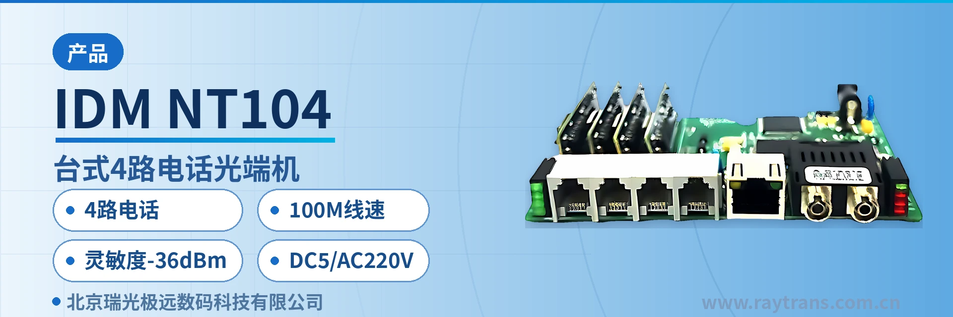
IDM-NT104 Desktop 4-Channel Telephone Optical Multiplexer
4 telephone + 1 Ethernet over same fiber, saves a pair of transceivers, desktop installation with no configuration required
The IDM-NT104 telephone optical multiplexer extends voice and data services to various user areas, replacing remote small offices, achieving cross-boundary line extension, and relieving the load on switching offices; or, within urban areas, it overcomes the bandwidth and transmission distance limitations of twisted pair, thereby expanding the service coverage of switching offices.
The IDM-NT104 desktop 4-channel telephone optical multiplexer is a 4-channel telephone and Ethernet same-fiber optical multiplexer developed by the optical multiplexer manufacturer Beijing Ruiguang Jiyuan Digital Technology Co., Ltd. (Raytrans), used to extend 4 telephone channels and 1 group of 100M Ethernet service to each user area. As a typical multi-service optical multiplexer, the device carries voice and data services in a desktop chassis and transmits them point-to-point over 1 optical fiber. It can replace remote small offices to perform cross-boundary line extension, and can also bypass the bandwidth and transmission distance limits of twisted pair within urban areas to expand the service scope of a switching office. It is a common product showcase form in government private network optical fiber communication solutions.
Key Specifications at a Glance: 4 telephone channels · 100M line-rate Ethernet · sensitivity -36dBm · DC5/AC220V dual power supply · 1310nm single-mode FC optical port · overall power consumption 25W
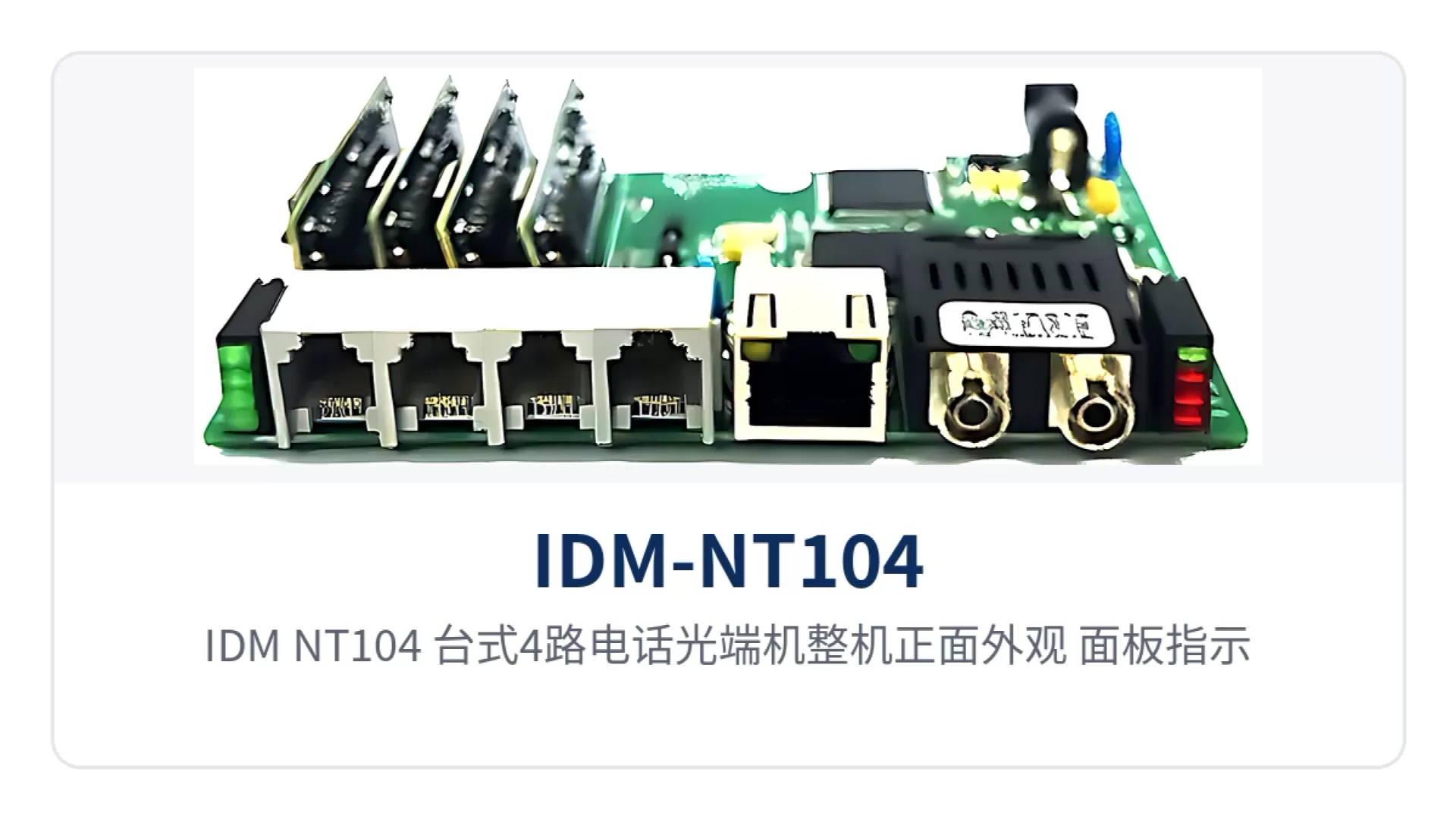
Figure 1: Front appearance of the IDM-NT104 desktop 4-channel telephone optical multiplexer, close-up of panel indicator LEDs and 4 telephone interfaces
Where this device fits in
For user points far from a switching office, twisted pair has upper limits in both bandwidth and transmission distance, and direct line assignment often fails to meet the enable conditions. As a practical telephone optical multiplexer, the IDM-NT104 collects the 4 telephone channels on the switching office side into a single optical fiber and restores them at the remote end into ordinary telephone interfaces. Telephones on the user side dial as usual and caller ID displays as usual, with the same listening experience as local line assignment.
1 group of 100M Ethernet channel is transmitted in parallel over the same optical fiber, so office terminals, surveillance front ends or data acquisition devices at remote stations need no additional network cabling and no additional pair of transceivers. Voice and data services are housed in a 125×100×46mm desktop chassis that fits on a cabinet tray or a duty desk, and no configuration interface is required during enablement. In the product showcase, this 4-channel telephone and Ethernet same-fiber optical multiplexer stands out for its compact structure and plug-and-play characteristics, making it suitable for rapid deployment at remote small stations.
What services can the 4-channel telephone and Ethernet same-fiber optical multiplexer carry
The service ports of the device are arranged in two categories, voice and data, and all services share 1 optical channel. The typical configuration of a 4-channel telephone and 1-channel Ethernet optical multiplexer is 4 voice channels plus 1 group of Fast Ethernet. The table below lists each function and its corresponding description item by item, which can be checked against the service list of the site; the interface type, fiber connection method and power supply mode take effect after confirmation at ordering.
| Function | Description |
|---|---|
| 4-channel telephone access | Provides 4 ordinary telephone interfaces with caller ID (CID), an audio range of 300Hz~3400Hz, ITU G.711 A-law compression, and a loop current of 25mA per channel |
| 100M line-rate Ethernet | 1 group of RJ-45 interfaces, 10/100Base-T adaptive, compliant with IEEE802.3, full/half duplex adaptive, with the Ethernet channel forwarding at 100M line rate |
| Telephone and data same-fiber transmission | 4 voice channels and 1 group of Ethernet are multiplexed into 1 optical channel, with single-fiber or dual-fiber connection optional, eliminating paired optical fibers and extra cabling |
| Desktop chassis structure | Chassis dimensions 125×100×46mm, high integration and small size, can be placed on a duty desk, in a wall-mounted box or on a communications cabinet tray |
| Alarm indication | The panel provides power and optical link status indication; when the link is abnormal, the LED position tells whether the failure lies in power supply or the optical path |
| Dual power supply modes | DC5 or AC 220V power supply modes are optional, and both AC mains power in equipment rooms and DC power at sites can be connected directly |
How to check the technical specifications
The specifications are listed in four groups: optical interface, Ethernet port, telephone interface, and power supply and environment. The devices at both ends are used in pairs, and the wavelength and interface type of the optical interfaces must match. The check order is to first calculate whether the link loss falls within the optical power budget, then confirm the number of voice channels and Ethernet ports, and finally check the power supply mode and installation space.
Optical Interface
| Item | Parameter/Specification | Description/Applicable Conditions |
|---|---|---|
| Interface type | FC (SC and others can be customized) | Selected according to the on-site optical cable termination method, avoiding temporary fiber adapter conversion on site |
| Fiber mode | Single-mode (multi-mode optional) | Single-mode is the standard configuration; multi-mode is confirmed per project |
| Optical channel | 1 channel | Used in pairs at both ends, with receive/transmit directions connected correspondingly |
| Optical fiber rate | 155bps±50ppm | As stated in the original product documentation; the actual optical port rate is subject to the manufacturer's technical documentation |
| Wavelength | 1310nm | The wavelength and interface type of the devices at both ends must be consistent |
| Transmit optical power | -2~-11dBm | Available optical power range on the transmit side |
| Receiver sensitivity | Better than -36dBm | Lower limit of available optical power on the receive side; weak optical links still have receive margin |
Ethernet Interface
| Item | Parameter/Specification | Description/Applicable Conditions |
|---|---|---|
| Interface type | RJ-45 | Connects to a switch, office terminal or surveillance front end |
| Transmission rate | 10/100Base-T, 10M/100M | The port accesses at the rate determined through adaptive negotiation |
| Standard protocol | Supports IEEE802.3 | Interoperates with mainstream network devices without protocol conversion |
| Operating mode | Full/half duplex/adaptive | Negotiated according to the capabilities of the peer port |
| WAN transmission rate | 100M line rate | Voice and data each occupy an independent channel inside the device and do not squeeze each other's bandwidth |
Telephone Interface
| Item | Parameter/Specification | Description/Applicable Conditions |
|---|---|---|
| Number of telephone channels | 4 channels | Ordinary telephone interfaces with caller ID (CID) |
| Audio range | 300Hz~3400Hz | Covers the full frequency band of telephone voice, consistent with the public telephone network |
| Impedance | Three-element complex impedance 200Ω+560Ω//0.1μF | Matches the SPC exchange and ordinary telephone side |
| Compression | ITU G.711 A-law | Common encoding of the domestic telephone network, interoperates directly with mainstream switching equipment |
| Loop current | 25mA per channel | Ensures normal power feeding and ringing of telephones |
Power Supply, Environment and Structure
| Item | Parameter/Specification | Description/Applicable Conditions |
|---|---|---|
| Power supply mode | DC5 or AC 220V | Select one of them for connection according to on-site power conditions |
| Overall power consumption | 25W | Equipment room heat dissipation and power supply capacity are calculated at 25W |
| Operating temperature | 0℃~50℃ (operating) | Equipment rooms, wiring closets and well-ventilated equipment boxes |
| Humidity | 95% non-condensing | The applicable condition for high-humidity environments is non-condensing |
| Dimensions | 125×100×46mm (Length×Depth×Height) | Desktop structure, can be placed on a desk, in a wall-mounted box or on a small cabinet tray |
What guarantees voice quality on weak optical long-distance links
A receiver sensitivity better than -36dBm means the device can still demodulate voice and data signals when the received optical power drops to a low level close to the threshold. The IDM-NT104 has a transmit optical power of -2~-11dBm, leaving power margin against the -36dBm receive threshold. Estimated at the -11dBm lower transmit limit, the available link loss is about 25dB, and at -2dBm it is about 34dB, so weak optical long-distance links can still maintain calls.
Aging splice points in old optical cables, dust on fiber adapter end faces and insufficient bending radius all bring extra loss, and such loss is absorbed by the above margin, so the link does not have to stop calls first because of low received optical power. In engineering practice, reserve 3dB at each end; when the budget is insufficient, first clean the end faces and reduce conversion fiber adapters, then consider replacing the optical module.
Voice quality is also determined by encoding and interface specifications: the audio range of 300Hz~3400Hz covers the full frequency band of telephone voice, ITU G.711 A-law is the common encoding of the domestic telephone network, and the loop current of 25mA per channel ensures normal power feeding and ringing of telephones. Voice quality reaches carrier-class level and matches the listening experience of local line assignment. As a professional optical multiplexer manufacturer, Raytrans has accumulated rich experience in multi-service optical multiplexers and government private network optical fiber communication solutions, and this product is a mature choice for integrated voice and data access at remote small stations.
Typical Application Scenarios
What the three types of private networks have in common is few people, scattered sites and a large maintenance radius; voice channels must work as soon as they are plugged in, and failures must be seen at a glance. As a typical telephone optical multiplexer product, the IDM-NT104 is deployed as a pair in point-to-point mode; once both ends are powered up and the optical fibers and telephones are connected, the service is enabled without on-site configuration, making it suitable for the following scenarios.
Power distribution networks and substations: dispatch telephone and in-station data backhaul over the same fiber
Substations, switching stations and power supply stations are distributed across urban and suburban areas, and most equipment rooms are unattended. The station needs both a dispatch voice channel that does not go through dialing and backhaul of meter and status data. This 4-channel telephone and 1-channel Ethernet optical multiplexer uses 4 telephone channels for in-station duty and dispatching calls and 1 group of 100M Ethernet for data backhaul, with both types of services transmitted over the same fiber, so old station upgrades do not need to lay new optical cables for data.
Power site power conditions vary: wiring closets in urban areas mostly have AC mains power, while suburban sites may have only DC power. The device supports DC5 and AC 220V power supply modes with an overall power consumption of 25W, so sites can draw power under existing conditions without adding a dedicated power distribution panel for this optical multiplexer.
Rail transit lines: telephone extension for section duty points and stations
Section duty points of rail transit and highway tunnels are scattered along the line, and most points need only one or two voice channels, with several kilometers of optical cable between the telephone and the station or train dispatch. The 4 telephone channels are extended to the section over a single optical fiber, so a duty operator goes off-hook and is connected to the station duty room, shift personnel do not need to relearn numbers and key sequences, and section cabling is reduced as voice and data share the same fiber.
Cabinets in tunnels and at portals are damp and dusty, and O&M personnel cannot easily perform segment-by-segment troubleshooting. The power and optical link indicator LEDs on the panel narrow the failure scope to either the power supply or the optical path, so duty personnel can state clearly when reporting a fault whether it is a power failure, no light or excessive attenuation, and the repair team can arrive with the corresponding tools and spares.
Military and government private networks: independent voice channels for command posts and duty posts
Calls between command posts, fixed sentry posts and duty posts require fixed paths and simple operation, especially when duty personnel rotate frequently and cannot rely on memorizing numbers. The 4 telephone channels of the IDM-NT104 run over independent optical fiber channels without going through public network switching, and voice and data each use their own channel over the same optical fiber, so an abnormality in one service does not affect the other. The requirements of such government private network optical fiber communication solutions for path independence and operational simplicity match exactly the channel design of this multi-service optical multiplexer.
The desktop chassis is small and suitable for paired deployment between temporary command posts, command vehicles and fixed sentry posts; once both ends are powered up and the optical fibers are connected, the service is enabled without relying on on-site software or network environment. The Ethernet port can connect to duty terminals or video backhaul devices, bringing data from duty posts back to the command post as well.
How to wire and enable on site
Wiring corresponds item by item by service type: telephones use telephone cords, Ethernet uses network cables, the optical path uses optical fiber patch cords, and power is connected according to on-site conditions. Before installation, check the number of interfaces at both ends and the receive/transmit direction of the optical ports, then enable item by item in the order below, so that after all services are turned on you do not lose track of which segment a failure lies in.
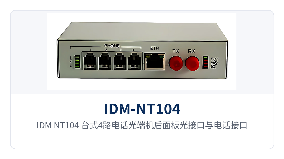
Figure 2: Rear panel optical interface and telephone interface layout of the IDM-NT104 desktop 4-channel telephone optical multiplexer, point-to-point networking connection diagram
- Fixing the equipment: one unit at each end, placed on the desktop, in a wall-mounted box, or on a communications cabinet tray at the switching office side and the remote station respectively, leaving heat dissipation clearance and operating space for the optical ports and telephone ports.
- Connecting telephones: connect the 4 telephone interfaces to the corresponding telephones or switching equipment voice channels, crimp according to the interface form confirmed in the ordering configuration, and label the opposite end name channel by channel to reduce later line tracing.
- Connecting data: connect the Ethernet port to a switch, office terminal, or surveillance front end with a network cable, and verify that the port is negotiated at 100M full-duplex.
- Connecting optical fibers: connect the 1 optical channel to the optical ports at both ends in single-fiber or dual-fiber mode, verify the receive/transmit direction and connector type, and select FC or SC according to the ordering configuration.
- Power-on check: connect the DC5 or AC 220V power supply, confirm that the front panel power indicator is normal, then go off-hook channel by channel to check ringing, call quality, and hang-up release.
- Measuring received optical power: measure the received optical power at both ends with an optical power meter and compare it with the receiver sensitivity threshold of better than -36dBm; if the received optical power is low, first clean the end face and the fiber adapter.
- Recording and archiving: register the device numbers at both ends, the optical port received optical power values, and the correspondence between voice channels and Ethernet ports, so that subsequent device replacement or capacity expansion can be restored by matching the records.
Conclusion
As a 4-channel telephone and Ethernet same-fiber optical multiplexer, the IDM-NT104 carries 4 telephone channels and 1 group of 100M Ethernet over a single optical fiber, saving a pair of optical fibers and an extra device for the remote station, and saving one small office build for the switching office. The device is applicable across three types of requirements—replacing remote small offices, cross-boundary line extension, and urban supplementary sites—with simple wiring relationships, and both commissioning and troubleshooting remain within what can be completed on site.
For access scenarios with scattered sites such as electric power distribution networks, rail transit lines, and military and government private networks, the IDM-NT104 maintains calls on weak optical links with receiver sensitivity better than -36dBm, maintains voice quality with G.711 A-law and 25mA per channel loop current, and adapts to inconsistent on-site power supplies with two power supply modes, DC5 and AC 220V, making it suitable as a desktop-type access device deployed as a pair for long-term online operation. Raytrans, as a professional optical multiplexer manufacturer, continues to provide stable and reliable product showcase and technical support for various private network access scenarios.


