
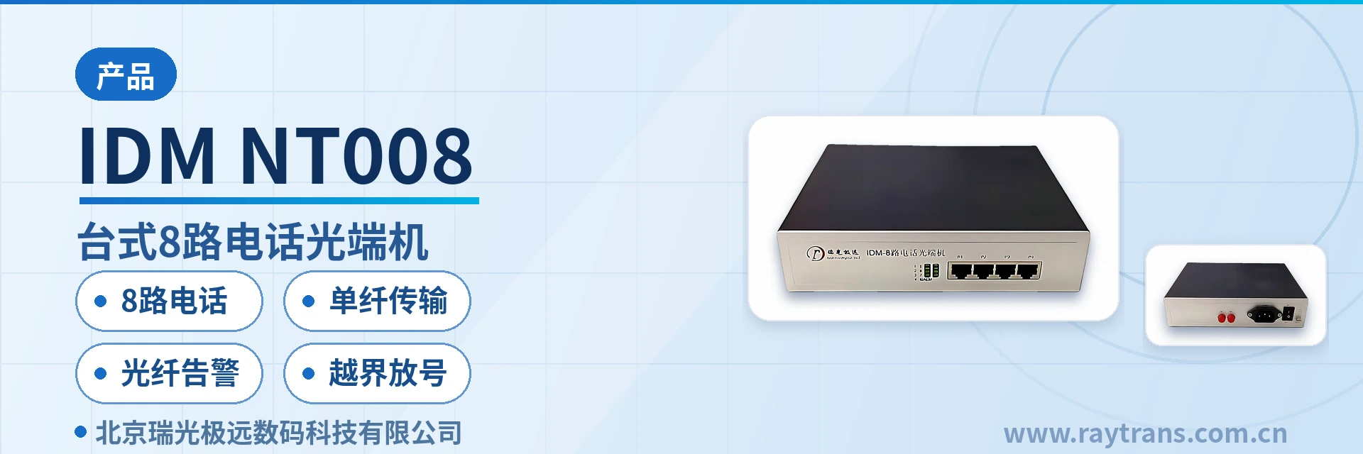
IDM-NT008 Desktop 8-Channel Telephone Optical Multiplexer
Single Fiber 8 Telephone Channels, 4 RJ45 Connector Ports, 2-Channel per Port, Troubleshooting by Indicator LEDs, Cross-Boundary Line Extension Without Building a Switching Office
The IDM-NT008 desktop 8-channel multi-service optical multiplexer provides 8 telephone interfaces through 1 optical fiber channel, and the 8-channel telephone optical multiplexer features high integration and compact size. The IDM-NT008 desktop 8-channel multi-service optical multiplexer extends voice and data services to various user areas and achieves cross-boundary line extension, serving as a substitute for remote small offices and deferred switching offices; alternatively, in urban areas it addresses the limitations of twisted pair in frequency band and transmission distance, expanding the service range of the switching office.
The single fiber telephone optical multiplexer IDM-NT008 is a desktop integrated service fiber access equipment developed by Beijing Ruiguang Jiyuan Digital Technology Co., Ltd. It is a representative model in the telephone optical multiplexer product line, designed with dedicated large-scale integrated circuits, and is used to provide 8 telephone interfaces to the user side through 1 optical fiber channel, extending voice and data services to various user areas and achieving cross-boundary line extension. Installing one desktop enclosure at the remote end allows the telephone services of the local switching office to cover remote users, serving as a substitute for remote small offices and deferred switching offices. As a professional optical multiplexer manufacturer, Raytrans has long been deeply engaged in the field of single fiber telephone optical multiplexers, and the equipment is also often used in scenarios such as government private network optical fiber communication solutions and military emergency communications vehicle solutions. For more information about multi-service optical multiplexers and the product showcase, please refer to the official materials of Raytrans.
Key specifications at a glance: Single fiber 8-channel telephone channels · 4 8P8C RJ45 connector ports (2-channel per port: pins 4/5 for the first channel, pins 3/6 for the second channel) · Loop current 25mA per channel · Audio 300Hz3400Hz · ITU G.711 A-law · Transmission distance generally 3040km · Compact desktop size
What Kind of Device Is a Single Fiber Telephone Optical Multiplexer?
A single fiber telephone optical multiplexer is a type of access equipment that extends the voice capability of a switching office to a remote end over 1 optical fiber. In a desktop enclosure, the Raytrans IDM-NT008 integrates 8 telephone interfaces and 1 optical fiber channel: the central office side connects to the analog user port of the SPC exchange and the remote end connects to ordinary telephones, with the two ends in point-to-point direct connection, so that voice runs over the dedicated optical fiber channel end to end and consumes no public network resources. This telephone optical multiplexer showcases the features of a desktop enclosure, namely high integration and compact size, making it suitable for installation in space-limited locations such as equipment rooms, wiring closets and business outlets.
The typical use of the IDM-NT008 is cross-boundary line extension: when remote users are far from the switching office and twisted pair cannot provide coverage in terms of frequency band and transmission distance, a pair of optical multiplexers completes single fiber 8-channel telephone subscriber line provisioning, and the service range of the switching office is expanded accordingly, with no need to build another switching office in a remote area. The equipment can be used for public telephone network access and dedicated line information transmission in sectors such as telecommunications data services, electric power, banking, public security, the military, schools and expressways.
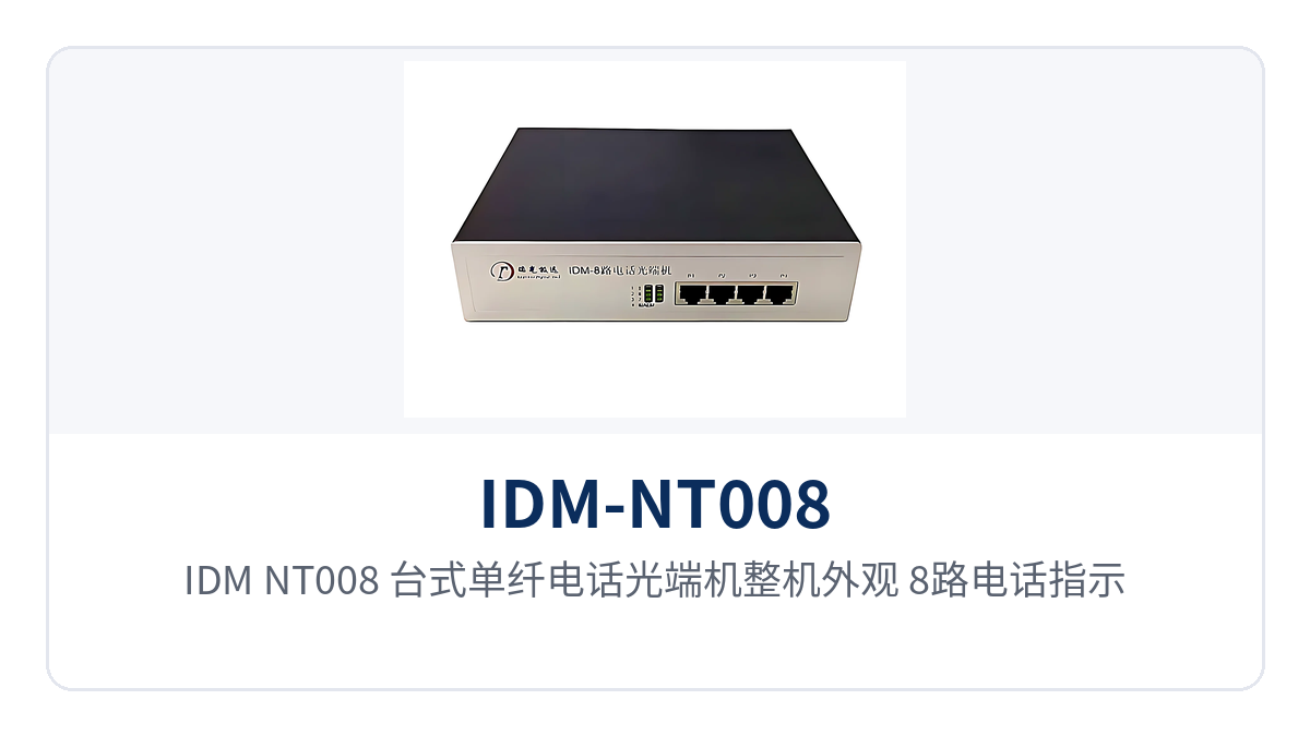
Figure 1: Overall appearance of the unit, the IDM-NT008 desktop single fiber telephone optical multiplexer, with a close-up of the 8 telephone indicator LEDs and the 4 8P8C RJ45 telephone interfaces
Differentiated Value: What Carrying 8 Telephone Channels over a Single Fiber Saves on a Project
The differentiated value of the IDM-NT008 centers on two aspects, coverage cost and O&M efficiency, which are explained item by item in the table below.
| Differentiation Point | Value Description |
|---|---|
| 8 Telephone Channels | A single unit provides 8 independent telephone channels with a loop current of 25mA per channel, meeting the requirements of multi-channel concurrency in industrial private networks. |
| Single Fiber Transmission | A single fiber carries 8 telephone channels, replacing remote small offices and enabling cross-boundary line extension, and eliminating the need to build switching offices. |
| Optical Fiber Alarm | Separate indicator LEDs for the in-use/ringing status of the 8 telephone channels plus the optical fiber alarm, enabling visual troubleshooting at unattended sites. |
| Cross-Boundary Line Extension | Voice is extended to remote areas over optical fiber, and the service range of the switching office is expanded accordingly, so no additional switching office is needed at the remote end. |
8-Channel Telephone Optical Multiplexer Function Overview
The functions and effects of the IDM-NT008 are shown in the table below.
| Function | Description |
|---|---|
| 8 Telephone Channels | A single unit provides 8 independent telephone channels for connecting 8 telephones or interfacing with 8 central office analog trunks. |
| 4 8P8C RJ45 Connector Telephone Interfaces | 8P8C interfaces, 2-channel per port: pins 4/5 for the first channel, pins 3/6 for the second channel, 8 channels in total. |
| 8 Telephone Indicator LEDs | Steady on indicates the telephone is in use, blinking indicates ringing, and off indicates the channel is idle. |
| Optical Fiber Alarm Indicator LED (8/ALM) | Blinking indicates an optical fiber link alarm, and the indication is off when the link is normal. |
| Single Fiber Point-to-Point Transmission | 1 optical fiber channel completes the connection between subscriber terminals or with the public switched telephone network (PSTN), with voice carried over the private network. |
| Cross-Boundary Line Extension | Voice services are extended to various user areas, replacing remote small offices and deferred switching offices. |
The front panel of the device has 9 indicator LEDs in total: telephone indications for channels 1 to 8, with steady on meaning the telephone is in use, blinking meaning ringing and off meaning the channel is idle; the channel 8 indication is shared with ALM by multiplexing, and there is a separate optical fiber alarm indication that flashes for an optical fiber link alarm and is off when the link is normal. When O&M personnel carry out inspections in an unattended equipment room, they can judge whether a channel is in use or there is an optical path fault just by looking at the LED status, without logging in to the network management system.
Key Technical Specifications
| Item | Parameter/Specification | Description/Applicable Conditions |
|---|---|---|
| Telephone Interface | 8 channels, 4 8P8C RJ45 connector ports | 2-channel per port: pins 4/5 for the first channel, pins 3/6 for the second channel |
| Audio Range | 300Hz~3400Hz | Meets the voice band requirements of the public telephone network |
| Compression Rate | ITU G.711 A-law | Standard PCM voice codec encoding method, in accordance with ITU-T Recommendation G.711 |
| Impedance | Three-element complex impedance 200Ω+560Ω//0.1μF | Matches the working conditions of standard analog telephone lines |
| Loop Current | 25mA per channel | Feeding capability of each telephone interface, supporting multiple channels to go off-hook and talk at the same time |
| Optical Fiber Channel | 1 optical fiber | A single fiber carries 8 telephone services |
| Transmission Distance | 30~40km in general configuration | Depends on the optical fiber type and the link loss situation; for longer distances, please confirm with the optical multiplexer manufacturer |
| Indicator LED | 8 telephone indication LEDs + optical fiber alarm indication | Steady on: in use, blinking: ringing, off: idle; a flashing alarm indication means an optical path alarm |
| Enclosure Type | Desktop | High integration and compact size, suitable for installation in space-limited locations |
Installation and Wiring Key Points
Installation of the IDM-NT008 consists of three parts, namely optical path interfacing, service wiring and checks after the device is powered on, and the equipment can be enabled by completing them in the following order.
- Optical path interfacing: connect 1 optical fiber to the optical port of the device and link it point-to-point with the device at the opposite end; after the fibers at both ends are connected and the device at the opposite end is powered on, the 8/ALM alarm indicator LED stays off, indicating that the optical path is normal.
- Service wiring: the telephone interfaces are 4 8P8C (RJ45) connector ports with 2-channel per port, pins 4/5 for the first channel and pins 3/6 for the second channel; the central office equipment connects to the analog user port of the SPC exchange and the device at the remote end connects to ordinary telephones.
- Power-on verification: the device is a desktop enclosure, so connect the power supply after positioning it so that the device is powered on; go off-hook and make a call on each channel in turn, and the corresponding port indicator LED changing from off to steady on means the channel is in use, while blinking means it is ringing.
- Troubleshooting sequence: first check whether the 8/ALM indicator LED is blinking to determine whether it is an optical path problem; then verify the wiring sequence of the RJ45 connector ports; next confirm whether the device at the central office and the device at the remote end are installed in reverse; and finally check whether the telephone itself is in good condition.
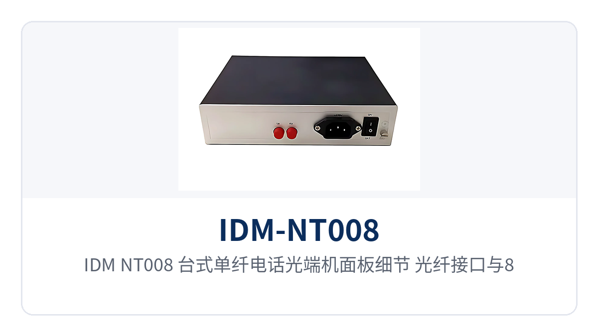
Figure 2: Panel details of the IDM-NT008 desktop single fiber telephone optical multiplexer, with a close-up of the optical fiber port and the 8/ALM optical fiber alarm indicator LED
Typical Application Scenarios
Private Network Voice Access for Remote Mining Areas and Oilfields
In mining areas and oilfields, the well stations and duty points are far from the switching office, and subscriber line provisioning over twisted pair is both limited by distance and prone to electromagnetic interference (EMI). With the Raytrans IDM-NT008, one desktop unit is installed at the central station and one at the remote well station, and 1 optical fiber between them carries 8 telephone channels, extending duty telephones and dispatch telephones to the well station; voice does not pass through the public network, and both on-site operations and dispatch communication use dedicated channels. One device covers 8 channels, and when multiple channels go off-hook at the same time, call setup is maintained by the loop current of 25mA per channel, making the equipment suitable for the multi-user concurrency of industrial private networks.
Communication Along the Line for Electric Power and Rail Transit
Telephone services at electric power substations and rail transit sites along the line are distributed along the route, and laying large-pair-count cable point by point is costly and susceptible to traction current interference. With one IDM-NT008 installed at each site along the optical cable already laid, up to 8 channels of voice service along the line can be connected to the trunk optical network, and call quality is not affected by line length or the electromagnetic environment. The compact desktop enclosure can be placed directly in the site communications cabinet or duty room, reducing the workload of station building modification.
Unattended Equipment Rooms and Cross-Boundary Line Extension
Sites such as unattended equipment rooms, pumping stations and base stations are unattended all year round, so it must be possible to see at a glance whether a telephone channel is in use and whether the optical path is normal. The IDM-NT008 uses 8 telephone indicator LEDs to distinguish the in-use and ringing states and an optical fiber alarm LED to distinguish optical path faults, so O&M personnel can make a preliminary judgment during an on-site inspection without carrying any instruments. In cross-boundary line extension scenarios, installing one desktop device at the remote end allows the telephone services of the switching office to cover remote users, eliminating the investment in building an additional switching office in a remote area.


