IDM-MUX30 Optical-Electrical Integrated Transmission Equipment
3 slots mixed, fully configured with 24 E1 plus 30 telephone channels; single-fiber carrying saves PCM and switches
The IDM-MUX30 30-channel SDH telephone optical multiplexer features a 155M optical interface, a standard 19-inch 1U chassis, and provides 4 groups of EOS 10/100M Ethernet interfaces; 3 service slots, where each slot of the IDM MUX30 optical-electrical integrated equipment can accommodate one 8*E1 board, totaling 24 E1 ports; or 8-channel/10-channel 64K subscriber services; or an 8-port Fast Ethernet switching board, or a 720P high-definition video input/output interface board.
IDM-MUX30 30-channel SDH telephone optical multiplexer is an STM-1 optical-electrical integrated transmission device developed by Beijing Ruiguang Jiyuan Digital Technology Co., Ltd. (Raytrans). It consists of an SDH optical transmission unit, 3 service slots, and PCM service cards, and is used to carry telephone, E1, and Ethernet services simultaneously over a single 155M optical fiber. It is an SDH device designed for private network access scenarios.
The device uses a 19-inch standard 1U chassis with dimensions of 440×230×45 (mm), occupying only one rack unit when installed in a standard communications cabinet. SDH, PDH, and IP access functions are integrated within the same chassis, so access nodes do not need separate transmission devices for voice, telecontrol data, and Ethernet, reducing cabinet space and cabling workload. As a professional SDH equipment manufacturer, Raytrans combines MSTP capabilities with a compact structure in this model, facilitating rapid deployment of optical transmission equipment in government private network optical fiber communication solutions and military emergency communications vehicle solutions.
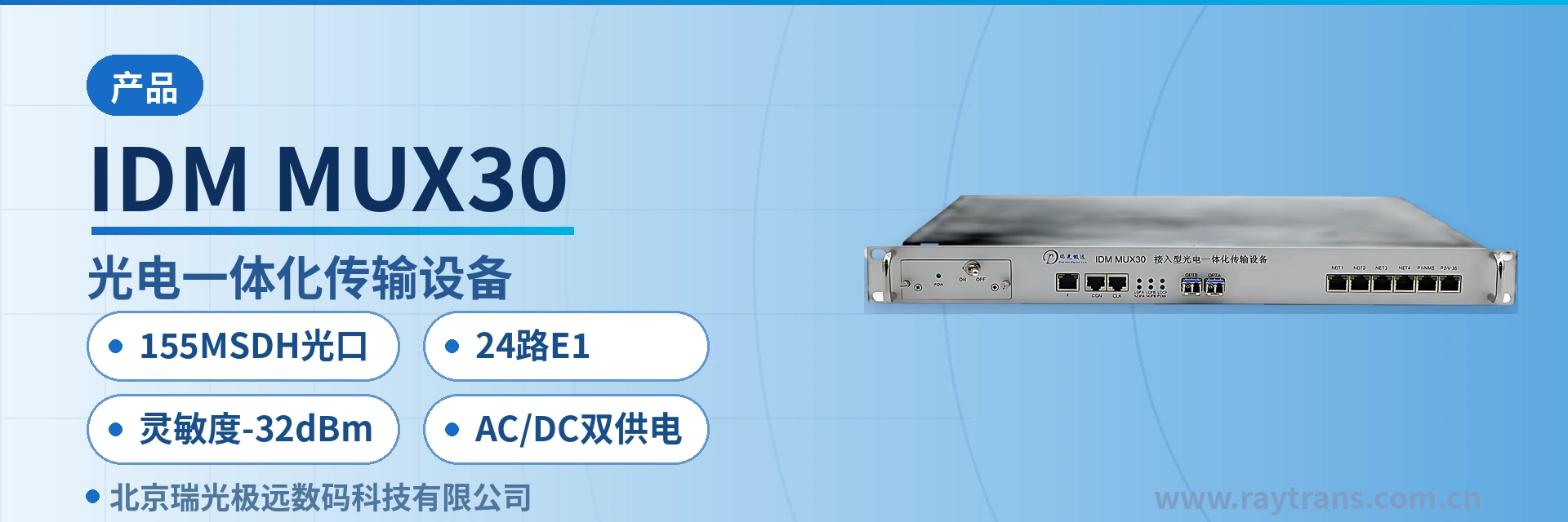
Key Specifications at a Glance: 155M SDH optical port · 24 E1 channels · -32 dBm sensitivity · AC/DC dual power supply · 19-inch 1U chassis · 10 W overall power consumption
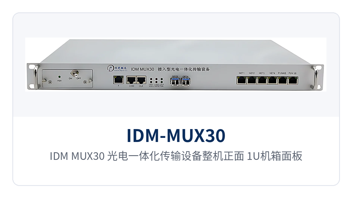
Figure 1: IDM-MUX30 optical-electrical integrated transmission device front view — close-up of the 1U chassis panel and optical link alarm indicator LEDs
What is a 30-channel SDH telephone optical multiplexer?
A 30-channel SDH telephone optical multiplexer is an access device that carries PCM voice services over the SDH hierarchy, with STM-1 on the line side and 64K subscriber interfaces and E1 on the tributary side. IDM-MUX30 is built around SDH and EOS technology, with a cross-connect capacity of 128×128 VC-12, and can allocate voice, E1, and Ethernet services to line time slots at VC-12 granularity. It is a typical SDH device for private network access scenarios.
The device is equipped with two 155.52 Mbps optical interfaces, A and B, and can be used as a terminal multiplexer or an add-drop multiplexer to build point-to-point, chain, and ring transmission networks, or to network jointly with a centralized MSTP system. On the line side, it can interconnect with STM-1 optical interfaces of standard-compliant SDH/MSTP equipment, so the existing transmission network does not need to be replaced entirely; during selection, simply verify against the interface specifications of the SDH equipment manufacturer for smooth network integration.
Why can a single 155M optical fiber carry telephone, E1, and Ethernet simultaneously?
The STM-1 line rate is 155.52 Mbps, and services use VC-12 as the basic container. Each VC-12 carries 2.048 Mbps, and one STM-1 can accommodate 63 VC-12s. The device allocates containers to E1, 64K voice, and EOS Ethernet according to the site service list, with Ethernet bandwidth allocated as N×VC12 (N≤50). Each service type occupies an independent container without preempting others. This VC-12-granularity allocation is exactly the typical use of MSTP and SDH equipment in private network access.
What cards can be inserted into the 3 service slots of IDM-MUX30?
The three service slots determine the service combination of a single device. Slots are populated card by card according to the site service list, and full population achieves maximum capacity. The voice channel and E1 capacity of the 3-slot mixed-insertion optical multiplexer varies with the number of inserted cards. The table below lists each function and its purpose row by row; during configuration, check against the site list to avoid missing voice channels, E1 directions, or Ethernet ports.
| Function | Description |
|---|---|
| SDH optical transmission | Two 155.52 Mbps optical interfaces, A and B, receive/transmit rate 155M/155M, wavelength 1310nm/1550nm, supporting chain and ring networking |
| 24-channel E1 access | Each of the 3 slots holds one 8×E1 card, providing 24 E1s at full population, compliant with ITU-T G.703, impedance 75Ω/120Ω, frame structure PCM30/31 |
| 30-channel 64K subscriber service | Each 64K service card provides 8 or 10 channels; three 10-channel cards provide 30 telephone lines in total, with FXO connecting to the exchange side and FXS connecting to telephones |
| 4 groups of EOS Ethernet | The main unit provides 4 groups of EOS 10/100M Ethernet interfaces, compliant with IEEE802.3, full/half duplex/adaptive |
| 8-port Fast Ethernet switching card | A single card provides 8 Fast Ethernet switching interfaces, allowing multiple terminals at a site to access locally without an additional small switch |
| 720P video interface card | The video input/output card carries 720P high-definition images, with surveillance video and voice sharing the same optical link |
| VC-12 cross-connection | Cross-connect capacity 128×128 VC-12, allocating time slots at 2.048 Mbps granularity, supporting path protection |
| Network element timing | Compliant with ITU-T G.813, supporting local crystal oscillator, line-derived, and external clock 2MBIT/2MHZ |
| Monitoring and alarm | Panel indicator LEDs display specific alarm states, and the device also outputs alarm information externally |
| Network management channel | Provides DCC, E1, N×64K, and TCP/IP management channels, supporting the simple network management protocol (SNMP) |
| Dual power supply optional | AC220V and DC-48V power supply formats are selectable, with overall power consumption of 10 W |
Voice services reside on the 64K service card: FXO interfaces connect to the exchange side, and FXS interfaces connect directly to telephones, with an audio range of 300 Hz to 3400 Hz and A-law companding per ITU G.711. Service cards are selected by voice channel direction, and a single device can hold cards of different directions simultaneously, completing number assignment and access in one configuration.
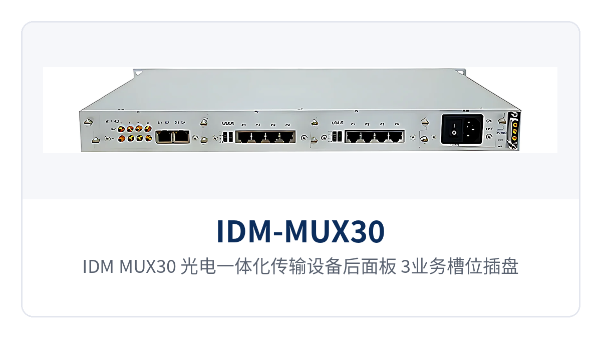
Figure 2: IDM-MUX30 optical-electrical integrated transmission device rear panel — layout of 3 service slots, E1/Ethernet interfaces, and power supply terminals
How to verify key specifications: optical ports, E1, Ethernet, and power supply
Specifications are listed in three groups: optical interfaces, E1 and Ethernet, and power supply and environment. The verification order is to first calculate the link optical power budget, then count voice channels and E1 directions, and finally confirm the power supply format and cabinet space. Sites with special interface requirements should state them at the time of ordering to avoid temporary on-site adapters.
Optical interfaces and transmission distance
| Item | Parameter/Specification | Description/Applicable Conditions |
|---|---|---|
| Interface type | FC (SC and others customizable) | Selected according to the on-site optical distribution frame and patch cord connectors |
| Fiber mode | Single-mode (multimode optional) | Single-mode for 20 Km links; multimode selected according to on-site optical cable |
| Receive/transmit rate | 155M/155M | STM-1 line rate, with consistent receive and transmit |
| Receive/transmit wavelength | 1310nm/1550nm | Wavelengths and interface types at both ends must be paired |
| Transmit optical power | -15~-8 dBm | Available optical power range at the transmit side |
| Receiver sensitivity | Better than -32 dBm | Receive threshold for weak optical links; distance calculated per optical power budget |
| Transmission distance | 20 Km | 20 Km over single-mode; long-distance optical modules can be optionally installed for longer transmission |
E1 and Ethernet interfaces
| Item | Parameter/Specification | Description/Applicable Conditions |
|---|---|---|
| Bit rate | 2048 Kbps | Standard E1 line rate |
| Line coding | HDB3 | Line coding compliant with ITU-T G.703 |
| Impedance | 75Ω/120Ω | 75Ω coaxial or 120Ω balanced, selected on site |
| Frame structure | PCM30/31 | 32 time slots per frame, with 30 time slots carrying services |
| Signaling | Channel-associated signaling | Voice channel status is conveyed together with the voice time slots |
| Maximum E1 count | 24 | Each of the 3 slots holds one 8×E1 card |
| Ethernet interface | RJ-45 | EOS 10/100M, compliant with IEEE802.3 |
| Ethernet bandwidth | N×2.048 Mbps (N≤50) | Allocated by VC-12 container, full/half duplex/adaptive |
Power supply, power consumption, and installation environment
| Item | Parameter/Specification | Description/Applicable Conditions |
|---|---|---|
| Power supply mode | AC220V/DC-48V | Dual power supply optional, selected according to site power conditions |
| Overall power consumption | 10 W | Low power draw and heat dissipation pressure for long-term online operation |
| Operating temperature | -15℃~+50℃ | Communications equipment room and field cabinet environments |
| Relative humidity | 0~95% (non-condensing) | Normal operation under non-condensing conditions |
| Dimensions | 440×230×45 (mm) | Length×Depth×Height, 19-inch 1U rack installation |
The optical power budget determines whether a link can be commissioned: with transmit optical power of -15~-8 dBm and receiver sensitivity better than -32 dBm, calculated at the lower transmit limit and the receive threshold, the available attenuation for a 20 Km single-mode link is approximately 17 dB. For links with many splice points or aged optical cables, the remaining margin can still support reception, so weak optical links do not require frequent optical module replacement.
How does 3-slot mixed insertion save cabinet space?
Bringing voice, E1, and Ethernet services into a single 1U device is the direct benefit of the 3-slot mixed-insertion structure. By allocating service cards according to the site service list, a single device can simultaneously carry telephone, telecontrol data, and Ethernet, so an access point does not need a separate optical multiplexer for each service type. There are four common card configurations:
- Voice-intensive sites: insert 10-channel 64K service cards into all three slots, providing 30 telephone lines from a single unit, with FXO and FXS cards selected by voice channel direction;
- E1-oriented sites: insert 8×E1 cards into all three slots, providing 24 E1s at full population, directly connecting to existing PCM or SDH tributaries;
- Data-oriented sites: insert 8-port Fast Ethernet switching cards, aggregating multiple terminals at the site locally before uplinking to the optical path;
- Sites requiring image upload: insert 720P video input/output cards, with surveillance video and voice sharing a single optical fiber.
Card configuration changes only the service cards; the chassis, optical ports, and external cabling remain unchanged, so capacity expansion does not require replacing the entire unit. For substations and trackside equipment rooms with limited cabinet space, one device replaces multiple single-function devices, reducing rack units and patch cords accordingly.
How to network a 30-channel SDH telephone optical multiplexer: chain, ring, and star
The networking approach is determined by site distribution: several sites connected in a line use chain networking, with each site along the line dropping off services in sequence; sites arranged in a loop use ring networking, where services travel in the other direction when one fiber path is interrupted; a central station connecting to multiple remote stations uses star networking, with one device at the central side aggregating services from all directions. As an SDH equipment manufacturer, Raytrans presents these three networking models in its product showcase, covering most private network site distribution patterns.
The device can serve as a terminal multiplexer or an add-drop multiplexer. Intermediate sites in a chain network only drop off local telephone and E1 services, while the remaining time slots pass through to downstream sites, so multiple SDH devices do not need to be stacked at intermediate sites. With dual optical ports and VC-12 path protection, network management and panel alarms can locate faults by section, and O&M personnel can check alarms before deciding whether to visit the site.
Differentiated value: 155M SDH optical port, 24 E1 channels, and dual power supply
Each of the three capabilities has verifiable specifications that can be written directly into technical specifications and bid parameter tables, and they are the main differences between this SDH device and ordinary optical multiplexers that carry voice only. All three hold simultaneously under the site conditions of electric power, rail transit, and military and government private networks.
| Differentiation Point | Customer Value |
|---|---|
| 155M SDH optical port, 24 E1 channels | Multiple services on a single unit, saving cabinet space: the STM-1 line side brings E1, 64K voice, and 4 groups of EOS Ethernet into one 1U chassis, so an access point does not need to cascade multiple single-function devices |
| -32 dBm sensitivity, 20 Km single-mode transmission | Stable operation on weak optical links: transmit optical power of -15~-8 dBm corresponds to a receive threshold better than -32 dBm, leaving power margin even on 20 Km spans with many optical cable splice points |
| AC/DC dual power supply, 10 W overall | Suited to unattended sites: both -48V DC distribution panels and 220V AC mains power can supply power directly, and 10 W power consumption reduces storage battery discharge pressure, so sites do not need inverters |
| 19-inch 1U, 440×230×45 (mm) | Occupies only one rack unit in a standard cabinet, installable in trackside equipment rooms and vehicle-mounted racks, and deployable even at sites with limited space |
Typical Application Scenarios
IDM-MUX30 targets three types of sites: electric power private networks, rail transit communication, and military and government private networks. The service card combination and power supply format are adjusted to site conditions, while the optical path and chassis remain uniform, and spare parts and O&M approach stay consistent as well. The access lists differ across the three site types, yet the card configuration approach can reuse the same method: first define the voice channels, then the E1 and Ethernet, and finally select the power supply format according to the on-site power source.
Electric Power Private Network: Substation Dispatch Telephone and Telecontrol Data Backhauled over the Same Fiber
Between substations and the dispatch center, both dispatch telephone and telecontrol, metering and monitoring data are carried. The device aggregates the E1 and 64 kbit/s services entering the station, configures the three slots according to the number of bays, and delivers voice channels and data to the dispatch center over the same 155M optical link, reducing the number of incoming optical cables and wiring.
Sites are mostly unattended, and the device is designed for -15℃+50℃ and 095% non-condensing humidity. The -48V DC distribution panel in the station can directly supply DC-48V power, and the 10W overall power consumption places little discharge pressure on the storage battery. When a new bay is added, only service cards and cross-connect configuration are added, while the chassis and external wiring remain unchanged.
Rail Transit Communication: Inter-Station Chain and Ring Networking, No Interruption on Weak Optical Links
Stations along the line, trackside equipment rooms and section substations are distributed over dozens of kilometers, and inter-station liaison telephone, broadcast control and monitoring data need to be aggregated at the central side. The device connects the stations in a chain, while in a ring, services are rerouted in the other direction when one fiber is abnormal, so inter-station communication does not stall entirely due to a single point of failure.
Section optical cables have many splice points and relatively high link attenuation; receiver sensitivity better than -32dBm leaves power margin on weak optical links. Service cards are configured according to the number of interfaces at each station: stations with heavy call handling get 64 kbit/s service cards, monitoring points get 8-port Fast Ethernet switching cards or 720P video cards, and O&M identifies the fault section based on the network management system and panel alarm indications.
Military and Government Private Networks: Direct AC/DC Dual Power Supply Access, 3 Slots Mixed as Required
Power supply conditions at field command posts, vehicle-mounted racks and temporary duty posts vary with the site: indoor equipment rooms have AC mains power, while vehicle-mounted and field sites mostly use DC power. AC220V/DC-48V dual power supply is optional, and sites take power according to existing power supply conditions without adding inverters or power distribution panels for the device. This feature also directly supports the rapid deployment requirements of military emergency communications vehicle solutions and government private network optical fiber communication solutions.
The 3 slots are mixed as required with E1, 64 kbit/s service, Fast Ethernet switching and video cards, so one device handles the access and upstream transmission of voice, data and image services. The 19-inch 1U chassis fits into a standard cabinet or vehicle-mounted rack, and the hoisting and wiring workload during mobile deployment decreases with the number of devices.
Selection and Deployment Recommendations
Selection is determined by five items: slot configuration, optical interface and distance, power supply format, installation environment and network management approach. The five items explain the check contents and common practices one by one, so on-site survey and commercial quotation can proceed in parallel, avoiding the discovery of interface or power mismatch only after delivery. As an optical multiplexer manufacturer and SDH equipment manufacturer, Raytrans recommends technical interfacing with the manufacturer at the survey stage to align the card configuration table in one pass.
- Slot configuration: first count telephone voice channels and E1 directions; for more voice channels, insert 10-channel 64 kbit/s service cards; for more E1, insert 8×E1 cards; for data-dominant sites, insert 8-port Fast Ethernet switching cards;
- Optical interface and distance: the optical interface is FC (SC and others can be customized); single-mode 20Km is the standard distance; for longer distances, long-distance optical modules are optional and the optical power budget must be calculated;
- Power supply format: choose AC220V for AC equipment rooms and DC-48V for DC sites; overall power consumption is 10W; wiring terminals and polarity are subject to the supplied technical documentation;
- Installation environment: operating temperature -15℃
+50℃, humidity 095% non-condensing; the 19-inch 1U chassis requires reserved rack space and heat dissipation space as required; - Network management and alarms: plan DCC, E1, N×64K or TCP/IP management channels, incorporate the device into the existing network management system via SNMP, and connect alarm outputs to equipment room monitoring.
Before deployment, align the site list with the card configuration table, pair the wavelengths and interface types at both ends of the optical modules, and power on only after verifying the power supply polarity. After commissioning, first check the panel alarm indications and optical link receiving status, then verify telephone and E1 channels one by one, and finally incorporate the device into the network management system for unified monitoring.