IDM 10G SDH Intelligent Multi-Service Optical Transmission Equipment
64K large cross-connect intelligent distribution eliminates the digital distribution frame; 155M to 10G online smooth upgrade
The SDH intelligent multi-service optical transmission equipment provides flexible equipment configuration with STM-64/16/4/1 compatible equipment; supports online upgrade of equipment from 155M to 10G. High-capacity cross-connect capability: 200×200 VC4, 600×600 VC3, 12600×12600 VC12 and 22400
The IDM 10G/2.5G SDH intelligent multi-service optical transmission equipment is an SDH intelligent multi-service optical transmission equipment developed by Beijing Ruiguang Jiyuan Digital Technology Co., Ltd. (Raytrans). It consists of a 19-inch card-based chassis, STM-64/16/4/1 optical interface units, a high-capacity TDM cross-connect unit, and various service access cards. Service cards can be mixed and inserted according to the project list and brought online, facilitating rapid product showcase and service provisioning.
The complete SDH intelligent multi-service optical transmission equipment is designed for backbone and aggregation nodes of electric power private networks, rail transit, and military and government affairs private networks. It consolidates E1 circuits, FE and GE Ethernet, and 64K audio and data services into a single cross-connect matrix, so the access layer no longer needs a separate narrowband multiplexer for each service type. As a professional SDH equipment manufacturer, Raytrans provides electric power private network SDH transmission solutions for power scenarios and meets the networking requirements of government private network optical fiber communication solutions with optical transmission equipment forms such as MSTP and MSAP.
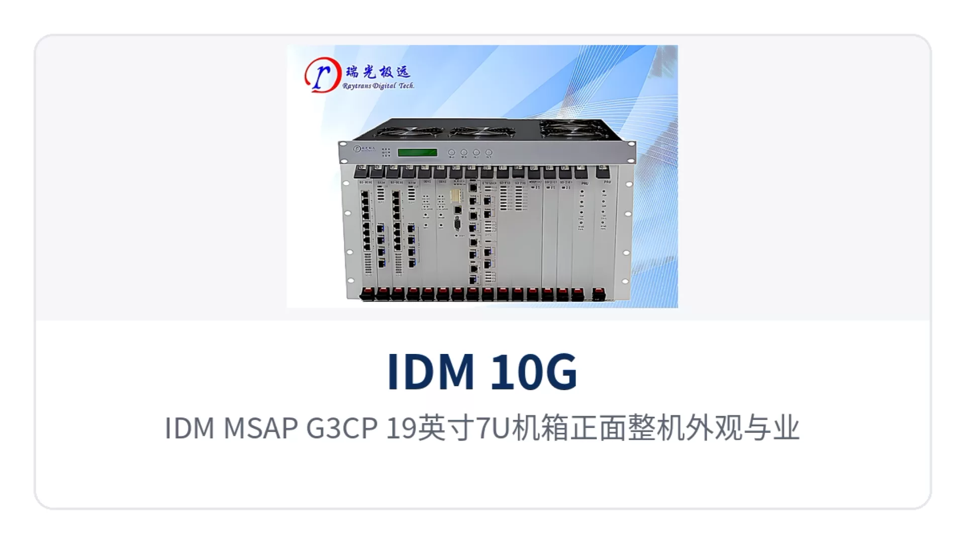
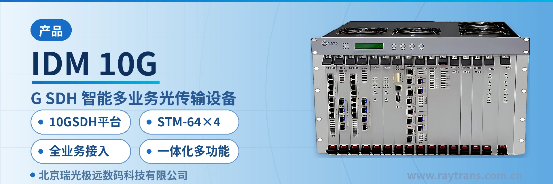
Figure 1: Front view and service slot layout of the IDM MSAP-G3CP 19-inch 7U chassis
Key Specifications at a Glance: 10G SDH platform · 22400×22400 cross-connect · STM-64×4 · full-service access · 504 E1 access channels · 7U and 3U chassis forms
What rates and interfaces does this SDH intelligent multi-service optical transmission equipment support
The optical interfaces cover four rate steps: STM-1, STM-4, STM-16, and STM-64. E1 tributary interfaces operate at the 2.048Mbps bit rate, HDB3 line coding, and PCM30/32 frame structure specified in ITU-T G.703, and Ethernet interfaces comply with IEEE 802.3. Cross-connect granularity is divided into four levels: VC-4, VC-3, VC-12, and 64K. Narrowband services and Ethernet services are scheduled within the same matrix, forming a complete SDH equipment product showcase system.
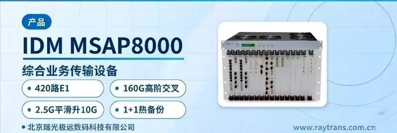
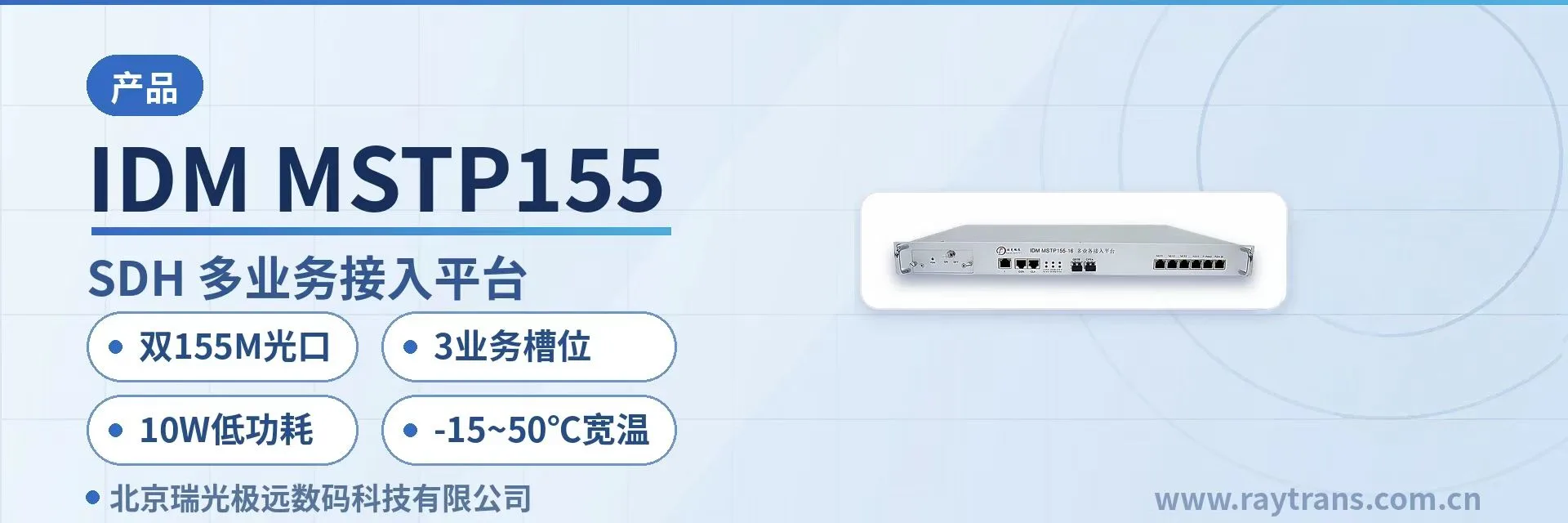
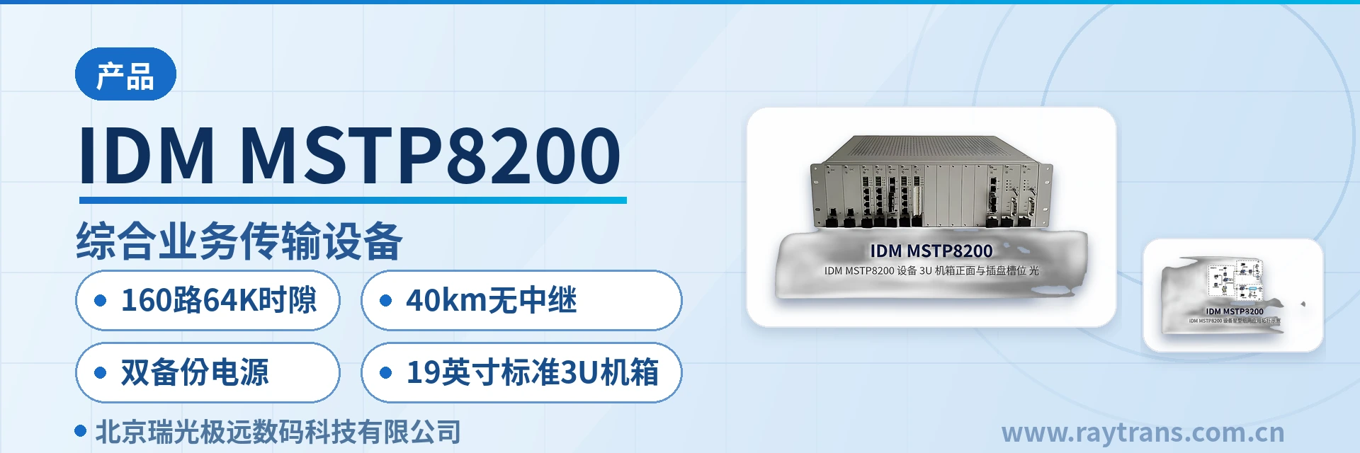
The differences among the three chassis forms lie in the number of service slots and the cross-connect capacity step, while the rate system and service types remain consistent. The 7U MSAP-G3CP carries 10G-level cross-connect capacity and more service cards; the 3U MSTP8000 trades 17 3U slots for rack height; and the 3U MINICP serves small and medium-capacity sites with 9 mixed slots. As a professional SDH equipment manufacturer, Raytrans adopts a unified card system and maintenance procedures across the three forms.
How to choose among the three chassis forms: 7U, 3U, and 3U mixed slots
Selection starts with the site's total service volume and rack margin, then the model is determined by cross-connect capacity step. The three forms support the same interface types; the differences concentrate on the number of service slots, cross-connect scale, and per-unit access limit. Check each item in the table below to decide.
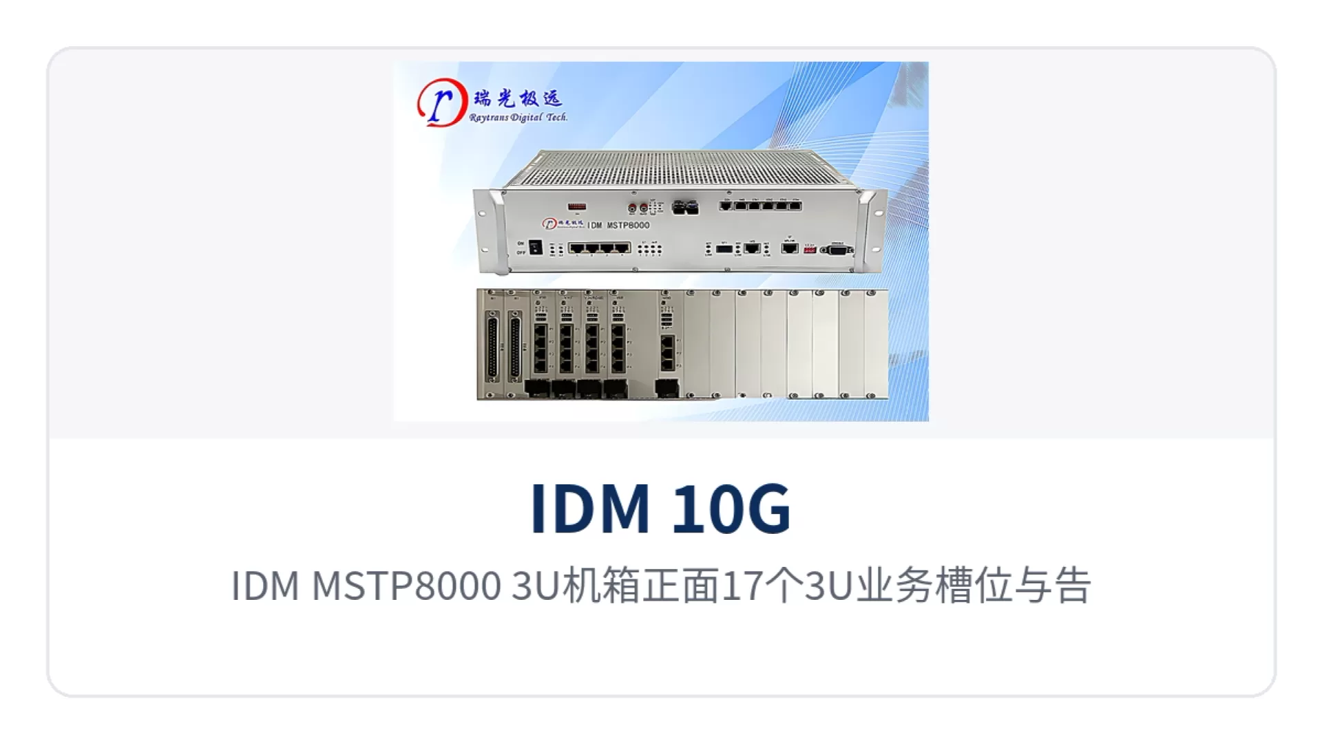
Figure 2: Front view of the IDM MSTP8000 3U chassis with 17 3U service slots and alarm indicator LEDs
| Chassis Form | Service Slots | Cross-Connect Capability | Suitable Sites |
|---|---|---|---|
| IDM MSAP-G3CP (7U) | 12 6U slots | 200×200 VC4, 600×600 VC3, 12600×12600 VC12, 22400×22400 64K | Backbone and aggregation equipment rooms with many service card types and optical directions |
| IDM MSTP8000 (3U) | 17 3U slots | 160×160 VC4, 480×480 VC3, 1440×1440 VC12, 2240×2240 64K | Aggregation equipment rooms with tight rack height and high slot demand |
| IDM MINICP (3U) | 9 (4×6U slots + 5×3U slots) | 160×160 VC4, 480×480 VC3, 1440×1440 VC12, 2240×2240 64K | Small and medium-capacity access sites and terminal stations |
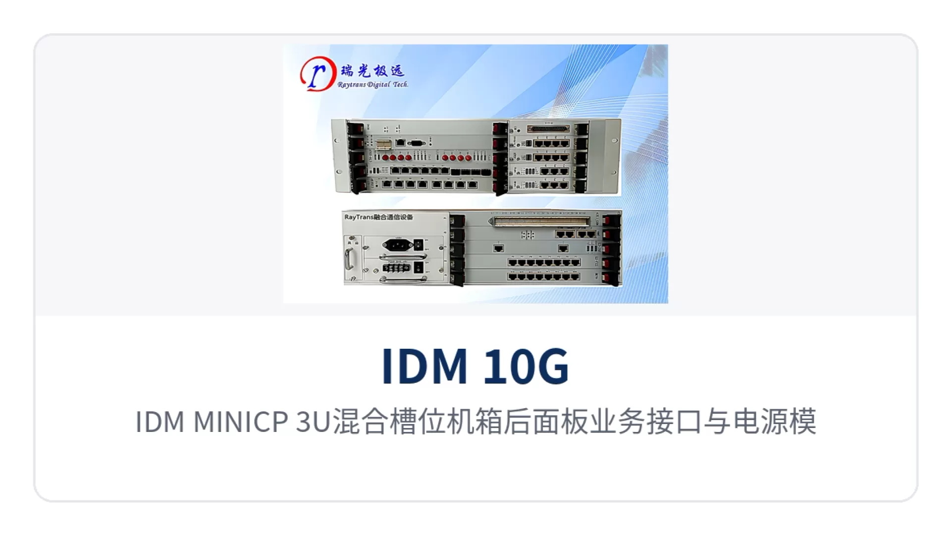
Figure 3: Rear panel service interfaces and power supply module layout of the IDM MINICP 3U mixed-slot chassis
The three forms share one rate and service system, cards can be managed under the same maintenance procedures, and spare parts are stocked to the same specification. When a site is upgraded from an access station to an aggregation station, it is enough to switch to a model with more slots according to service volume; the service card configuration list and O&M practices do not need to be redone. This design approach also facilitates a unified selection basis for electric power private network SDH transmission solutions and government private network optical fiber communication solutions.
What problems do the 22400×22400 cross-connect and intelligent patching solve
The 22400×22400 cross-connect means the cross-connect matrix uses 64K time slots as granularity and provides any-to-any connection capability between 22400 input time slots and 22400 output time slots. A 64K time slot is the bandwidth occupied by a single voice channel in the PCM30/32 frame structure. One E1 is organized into 32 time slots, of which 30 carry services and time slot 0 is used for frame alignment and alarms.
On top of the matrix, three types of intelligent patching capabilities are provided. Intelligent optical patching schedules optical directions at the VC-4 level; intelligent digital patching replaces physical digital distribution frames by 2M time slots; and intelligent voice patching replaces voice distribution frames by 64K time slots. To change a circuit, only the cross-connect configuration is modified, with no need to re-jumper in the equipment room.
A single unit can support digital patching of 12600×12600 2M time slots and voice patching of 22400×22400 64K time slots. With distribution frames gone from the equipment room, patching workload, distribution cabinet footprint, and points of failure are all reduced, and no space needs to be reserved for new jumpers during capacity expansion.
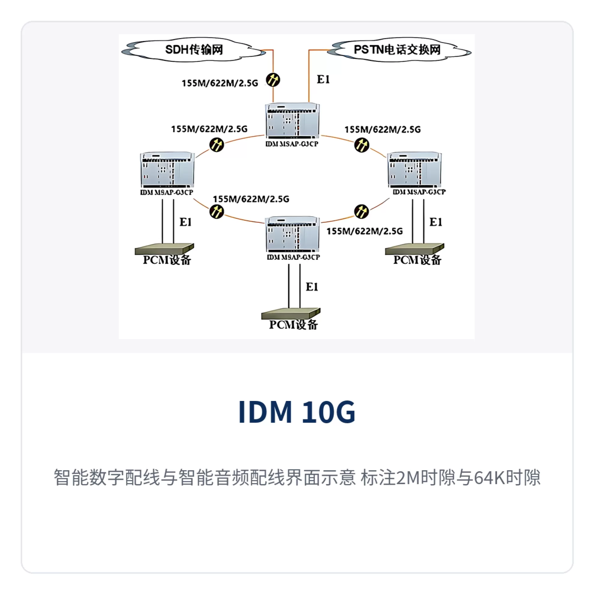
Figure 4: Intelligent digital patching and intelligent voice patching interface diagram, showing the cross-connection relationship between 2M time slots and 64K time slots
64K time slot cross-connection supports three modes: cross-connection with signaling, cross-connection without signaling, and signaling-modifying cross-connection. Cross-connection with signaling passes voice channels together with channel-associated signaling through the network, while signaling-modifying cross-connection rewrites signaling content at the cross-connect stage, which is used to unify signaling formats when interconnecting with existing PCM switching equipment.
Full-service access capability: service types and interfaces in one table
The complete optical transmission equipment concentrates optical transmission, cross-connection, service access, and network management in the same chassis. The functions and their roles are listed in the table below. When checking a configuration, compare item by item against the project service list: first confirm the interface type, then calculate the number of service cards and slot occupation.
| Function | Description |
|---|---|
| Flexible equipment configuration | STM-64/16/4/1 compatible, supporting smooth upgrade from 155M to 10G |
| High-capacity cross-connect capability | 200×200 VC4, 600×600 VC3, 12600×12600 VC12, and 22400×22400 64K cross-connect, provided by the MSAP-G3CP model |
| Intelligent patching | Intelligent optical patching, intelligent digital patching, and intelligent voice patching, replacing traditional physical digital distribution frames and voice distribution frames |
| Multi-service provision | Provides STM-1/4/16/64 optical interfaces, E1 interfaces, GE and FE Ethernet interfaces, N×64K E1/V.35 interfaces, and PCM interfaces such as FXO/FXS/EM/V.24/magneto |
| High integration | Three forms: 7U chassis with 12 6U slots, 3U chassis with 17 3U slots, and 3U chassis with 9 mixed slots |
| Strong networking capability | Supports ring, chain, star, tangent ring, and mesh topologies; a single chassis can implement STM-4/16/64 dual-fiber rings or four-fiber rings |
| Network survivability mechanisms | Supports SDH protection mechanisms such as 2F/4F MSP and optical port 1+1 |
| Equipment protection mechanisms | Main control 1+1 hot standby, cross-connect and clock 1+1 hot standby, power supply 1+1 hot standby |
| NMS platform | Supports SNMP protocol and provides management, configuration, monitoring, and statistics functions |
| Communication convergence expansion | Physically isolated gigabit EOS expansion card and fast Ethernet EOS expansion card, 10GE and 2GE+8FE all-optical switching card, 4G LTE access card, command and dispatch server card, SIP voice trunk card and digital trunk card, 1.25G/2.5G/5G/10G PDH optical access card, optically isolated IO expansion card, single-E1 and multi-E1 bridge cards |
| Equipment monitoring and testing | Line side and equipment loopback tests on optical ports, EOS Ethernet, and E1 ports; E1 in-service BER test; standard audio test; optical power and receiver sensitivity monitoring |
Service cards are divided by interface family: voice, data, Ethernet, and bridge services are each carried by corresponding cards, and cards can be mixed in the same chassis, with slots calculated by accumulating the number of cards. 64K narrowband services fall into three categories: audio, data, and IP packet. The specific interface types are shown in the table below.
| Service Category | Interface Type |
|---|---|
| 64K audio PCM services | FXS, FXO, EM2/4 audio, channel-associated signaling magneto, 2100Hz magneto |
| 64K data PCM services | RS232/RS485/RS422, X.50/X.58, codirectional 64K, CAN bus |
| 64K IP packet PCM services | n×64K bridge, N×E1 bridge |
The three types of 64K services are assigned time slots within the same cross-connect matrix, so audio and data do not each occupy a separate transmission channel. A site only needs to calculate the total time slot volume once based on the number of voice channels, data channels, and bridge bandwidth, then convert it into the corresponding number of service cards and slot occupation. The convergence of the above MSTP and MSAP capabilities on the same platform enables Raytrans equipment to cover the multi-service access requirements in both electric power private network SDH transmission solutions and government private network optical fiber communication solutions.
How is smooth upgrade from 155M to 10G implemented
Upgrade proceeds step by step by optical port rate, while the chassis, service cards, and external optical cables remain unchanged during the process. The implementation sequence is arranged according to site conditions, and at each step the cross-connect assignment and alarm state can be checked on the NMS before proceeding to the next step.
- First check the live network's optical port rate, chassis slot margin, and optical cable attenuation to determine whether the target rate step is STM-4, STM-16, or STM-64;
- Replace or add optical interface cards of the corresponding rate, and complete cross-connect assignment and clock source settings for the new optical direction on the NMS;
- For service expansion, only add or replace service cards; the chassis, backplane, and user-side patching remain as they are;
- When the cross-connect capacity step needs to be raised, adjust the cross-connect card and main control card according to the model configuration list; the specific plan is subject to the manufacturer's technical documentation and commercial confirmation.
The value of smooth upgrade from 155M to 10G lies in the fact that existing investment does not become obsolete as the rate step changes. Early sites first deploy STM-1 optical ports to carry E1 and small-granularity Ethernet; as services grow, they switch to STM-4 and STM-16 optical port cards and can ultimately upgrade to STM-64. Each upgrade touches only the optical interface side, while user-side wiring and service cards remain in use as before. For the long-term evolution of electric power private network SDH transmission solutions and government private network optical fiber communication solutions, this step-by-step upgrade path allows SDH equipment to continue delivering value across different service stages.
How to configure networking and protection mechanisms
Networking topologies support ring, chain, star, tangent ring, and mesh; a single chassis can implement STM-4, STM-16, and STM-64 dual-fiber rings or four-fiber rings. For cross-site networking, 64K time slots are assigned to the corresponding optical directions according to service assignment, and time slot planning is arranged once along with the site list. For the multi-site networking requirements common in product showcase, the time slot assignment method of this SDH equipment can be completed directly on the NMS.
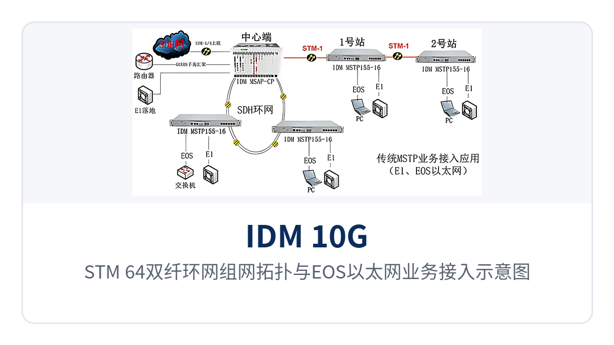
Figure 5: STM-64 dual-fiber ring network topology and EOS Ethernet service access diagram
Protection mechanisms are configured by layer. At the SDH layer, 2F/4F MSP and optical port 1+1 are enabled, so that services are switched to the backup channel when a single-segment fiber fails; at the device level, 1+1 hot standby is configured for the control, cross-connect, clock, and power supply; on the maintenance side, alarms, performance, and configuration change records are viewed through SNMP network management. As a professional SDH equipment manufacturer, Raytrans provides complete network management support for protection mechanism configuration.
Chain networks suit routes with long hop distances and few sites, while ring networks suit metro and private network backbones with bidirectional routing conditions. Tangent rings and mesh topologies are used for cross-region interconnection, with services intercommunicating between the two rings through cross-connection provisioning, so no separate transmission device needs to be added for interconnection. In electric power private network SDH transmission solutions, tangent ring structures are commonly used for cross-region interconnection between substations and dispatch centers.
Key Specifications
The following specifications are taken from the product documentation of the IDM 10G/2.5G SDH intelligent multi-service optical transmission equipment, with access quantities counted per standalone unit at full slot configuration. The specific slot configuration, service card models, and ordering combinations are subject to the manufacturer's technical documentation and commercial confirmation.
| Item | IDM MSAP-G3CP | IDM MSTP8000 | IDM MINICP |
|---|---|---|---|
| Dimensions | 19-inch 7U | 19-inch 3U | 19-inch 3U |
| Number of service slots | 12 | 17 | 9 (4×6U slots + 5×3U slots) |
| Equipment rate | STM-64/16/4/1 | STM-64/16/4/1 | STM-64/16/4/1 |
| Cross-connect capacity | 200×200 VC4, 600×600 VC3, 12600×12600 VC12, 22400×22400 64K | 160×160 VC4, 480×480 VC3, 1440×1440 VC12, 2240×2240 64K | 160×160 VC4, 480×480 VC3, 1440×1440 VC12, 2240×2240 64K |
| STM-64 standard or cascaded | 4 | 4 | 4 |
| STM-16 standard or cascaded | 40 | 4 | 4 |
| STM-4 standard or cascaded | 40 | 4 | 4 |
| STM-1 service | 56 | 10 | 4 |
| E1 service | 504 | 24 | 252 |
| Fast Ethernet (FE) | 40 | 28 | 16 |
| Gigabit Ethernet (GE) | 40 | 16 | 16 |
The clock and 64K service types are technical specifications shared by the three models and are listed item by item in the table below. During planning, verify the service card models against the actual interface types at the site, select the clock source on the network management system according to networking conditions, and note that the three types of 64K services can be mixed at the same site. The MSTP and MSAP platforms are consistent in service card compatibility, which facilitates unified spare parts management.
| Item | Parameter/Specification | Description |
|---|---|---|
| Clock characteristics | Master clock, external clock (2.048MHz, 2.048Mbps), clock extracted from optical port | Select the clock source according to networking conditions; cross-connect and clock support 1+1 hot standby |
| 64K audio PCM services | FXS, FXO, EM2/4 audio, channel-associated signaling magneto, 2100Hz magneto | Adapts to automatic telephones, common-battery and magneto telephones |
| 64K data PCM services | RS232/RS485/RS422, X.50/X.58, codirectional 64K, CAN bus | Low-speed data, telecontrol, and fieldbus services |
| 64K IP packet PCM services | n×64K bridge, N×E1 bridge | Ethernet services transparently transmitted over E1 or n×64K channels |
The STM-64, STM-16, and STM-4 quantities in the table refer to the number of access channels in standard interface or cascaded mode, while the E1 and Ethernet quantities vary with service card configuration. For capacity planning, first calculate the number of E1 channels and the total time slots according to the service list, then check whether the cross-connect capacity step of the model leaves sufficient margin. For aggregation nodes in government private network optical fiber communication solutions, it is recommended to select the model by cross-connect capacity step first, so as to avoid capacity expansion constraints later.
Differentiated Value: Which On-Site Problems These Four Capabilities Address
The capability differentiators of this Raytrans SDH intelligent multi-service optical transmission equipment correspond item by item to customer on-site problems. Before configuration, use the table below to determine which model and which type of service card are needed, then return to the parameter table to calculate access quantities, so as to avoid unnecessary margin at both the model and slot levels. The Raytrans brand has accumulated extensive private network deployment experience in the field of optical transmission equipment, and the following four capabilities have all been verified on site.
| Differentiation Point | Customer Value |
|---|---|
| 10G SDH platform: a standalone unit supports 22400×22400 64K cross-connection | Voice, data, and Ethernet services at an aggregation node are scheduled in the same matrix, with no need to cascade multiple narrowband multiplexers |
| STM-64×4: four STM-64 optical ports per standalone unit, compatible with STM-16/4/1 | A 10G backbone ring can be formed with one device, optical directions at a site are configured as services increase or decrease, and the rate step is not locked |
| Smooth upgrade from 155M to 10G | Early STM-1 sites upgrade step by step by replacing optical port cards as services grow, while the chassis, service cards, and external optical cables continue to be used |
| Full-service access: E1, FE, GE, and 64K audio and data | One platform covers circuit services, Ethernet, and narrowband services, reducing the variety of spare parts and unifying O&M practices |
There is a configuration sequence among the four capabilities. Cross-connect capacity determines how many time slots can be carried, optical port rate determines the upper bandwidth limit per direction, service cards determine which interface types can be connected, and the upgrade path determines how long this investment can be used. Only by checking all four together against the site list can any one step become a bottleneck be avoided. In electric power private network SDH transmission solutions, matching cross-connect capacity with optical port rate is particularly critical.
Typical Application Scenarios
Electric power private networks, rail transit, and military and government affairs private networks are the three main application areas of this system. The three scenarios differ in requirements for time slot scheduling, protection mode, and chassis form, and their configuration priorities also differ. The networking and service card descriptions below should be applied according to on-site conditions.
Electric Power Private Networks
In electric power private networks, dispatch telephones, telecontrol data, and video backhaul run simultaneously between substations and dispatch centers. The entire system uses STM-16 or STM-64 optical ports to form a dual-fiber ring network, collecting the E1 protection channels and Ethernet services of each station into the same cross-connect matrix, with dispatch voice carried by FXS, FXO, or magneto service cards. This electric power private network SDH transmission solution has been deployed at multiple substation sites, and the SDH-layer ring network protection can meet the reliability requirements of unattended substations.
Ring network protection and 1+1 hot standby of the control, cross-connect, clock, and power supply ensure that an unattended substation still has available channels when a single-segment optical cable or a single card fails. Adding a new bay requires only changes to the cross-connect configuration and service cards, while optical cables and cabinets remain unchanged; before the equipment is put into operation, simply verify the time slot occupation once against the site list.
Rail Transit
Along rail transit lines, stations, depots, and traction substations have short hop distances and dense sites. E1 carries signal interlocking and block services, while train dispatching telephones and section broadcasting run over 64K audio channels. The entire system uses STM-4 or STM-16 optical ports to form a chain network or ring network, and services along the line are provisioned by station at the central side.
After inter-station services are concentrated into one 3U MSTP8000 or MINICP, the number of devices and cables in the equipment room decreases. The network management system is incorporated into unified line monitoring through SNMP, and fault location changes from site-by-site inspection to checking alarms first and then performing loopback tests on optical ports and E1 ports.
Military and Government Affairs Private Networks
Nodes in military and government affairs private networks are distributed across fixed equipment rooms, command posts, and vehicle-mounted platforms, with varying power supply and rack conditions. The entire system adapts to different racks with 7U and 3U chassis forms, and service cards are mixed according to the on-site list to provide E1, Ethernet, audio, and bridge services. Government private network optical fiber communication solutions usually require equipment to support mixed insertion of multiple services, and the combination of this SDH equipment and the MSAP platform can meet such requirements.
When intercommunication with existing communication systems is required, SIP voice trunk cards, digital trunk cards, dispatch server cards, or 4G LTE access cards can be inserted to bring transmission and dispatching into the same chassis. Optically isolated IO expansion cards are used for on-site status quantity acquisition and control, preventing interference from external lines from entering the equipment.
Conclusion
As a set of SDH intelligent multi-service optical transmission equipment, the IDM 10G/2.5G SDH intelligent multi-service optical transmission equipment brings the 10G SDH platform, 22400×22400 cross-connection, STM-64×4 optical ports, and full-service access into one series, covering backbone aggregation and access sites with 7U and 3U chassis forms. In electric power private network SDH transmission solutions, this series can rely on MSTP and MSAP mechanisms to achieve isolated multi-service bearing; for government private network optical fiber communication solutions, it can likewise provide smooth evolution from 155M to 10G in the form of optical transmission equipment, and Raytrans has accumulated mature deployment experience in this field.
The equipment is supplied in rate steps from 155M to 10G, so sites can be upgraded step by step as services grow, and chassis, service cards, and external optical cables are not discarded when rates change. When changing models within the same series, the cross-connect configuration and time slot planning can be migrated according to the original list, and the workload of relocation and cutover is concentrated on the optical port and card side.
Before deployment, calculate the number of voice channels, data channels, and Ethernet channels according to the site service list, then determine the chassis form, cross-connect capacity step, and service card configuration. Time slot planning, protection mode, and clock source selection should be verified together with the manufacturer's technical support, and after the equipment is put into operation, periodic inspection should be carried out based on the alarm and performance data of the SNMP network management system.