IDM MSTP155-63 SDH Multi-Service Transmission Platform
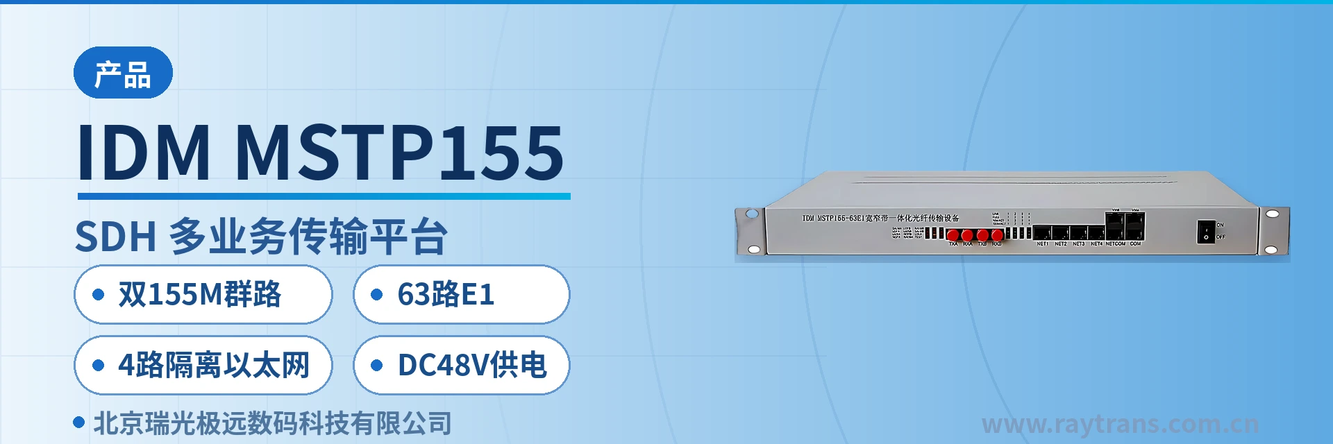
Dual 155M aggregate
The IDM MSTP155-63E1 multi-service transmission platform is an STM-1 level synchronous digital hierarchy (SDH) optical transmission equipment that supports two 155.52 Mb/s aggregate optical interfaces (A and B), 63 E1 interfaces, 4 physically isolated Ethernet channels with N*2.048Mbps bandwidth, and 2 V.35/V.11 interfaces. The IDM MSTP155-63E1 can serve as an add-drop multiplexer (ADM) and, as a transmission network node, provides add-drop multiplexing for 63 E1 channels;
IDM MSTP155-63E1 is a dual 155M aggregate SDH transmission platform developed by SDH equipment manufacturer Beijing Ruiguang Jiyuan (Raytrans), designed to carry 63 E1 channels, 4 physically isolated Ethernet channels, and 2 V.35/V.11 data services simultaneously over a single STM-1 optical fiber link. The two 155.52 Mb/s aggregate optical interfaces, A and B, correspond to two transmission directions respectively, and a single SDH equipment can act as an add/drop multiplexer (ADM) to add/drop and multiplex the 63 E1 channels.
The platform can also be used as a terminal multiplexer (TM), serving as the optical transmission module of a switch or service device to feed E1 channels and Ethernet services into an existing SDH transmission network. The overall technical performance complies with ITU-T and domestic SDH specifications, with VC-12 full cross-connect and path protection capabilities, and it can be directly connected to the STM-1 optical interfaces of any standard SDH/MSTP equipment, making it a typical multi-service access platform in the optical transmission equipment product showcase.
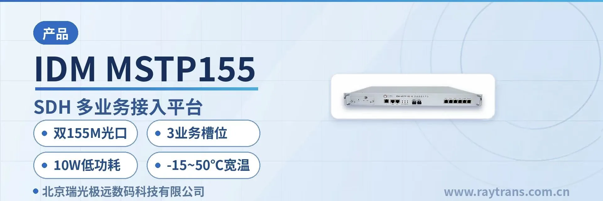
Private network access sites often face simultaneous constraints on rack position, fiber core, and power supply access, yet dispatch telephones, telecontrol E1 channels, and office surveillance networks run in parallel within the station. The platform uses a 19-inch 1U chassis with unit dimensions of 440×230×45 mm, and can be installed directly into a communications rack; a single 155M optical path delivers all three service types into the transmission ring at once, so the site side no longer needs a separate optical multiplexer for each service type. It is suitable for scenarios such as government private network optical fiber communication solutions and military emergency communications vehicle solutions.
Key Specifications at a Glance: Dual STM-1 optical ports · 63 E1 channels · 4 physically isolated Ethernet channels · 2 V.35/V.11 channels · Receiver sensitivity better than -32 dBm · AC 220 V/DC 48 V · 19-inch 1U chassis
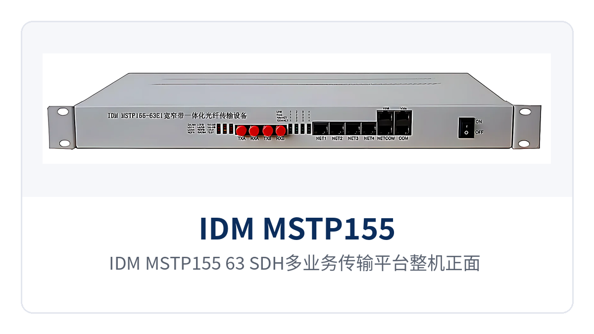
Figure 1: Front view of the IDM MSTP155-63 SDH multi-service transmission platform, showing the 19-inch 1U chassis panel and optical link operating indicator LEDs
What is a dual 155M aggregate SDH transmission platform?
A dual 155M aggregate SDH transmission platform is SDH transmission equipment operating at the STM-1 rate level. The two 155.52 Mb/s optical interfaces on the aggregate side can back up each other or serve two transmission directions separately; on the tributary side, E1, Ethernet, and low-speed data are multiplexed into VC-12 containers and sent to the opposite end over the same optical path. As a mature optical transmission equipment, the platform is often highlighted in the product showcase for its dual aggregate ports and high-density tributary interfaces.
The STM-1 transmission capacity specified by ITU-T is divided by byte interleaving into 63 VC-12 containers, each carrying one 2.048 Mb/s E1 signal, so a single STM-1 aggregate corresponds exactly to 63 E1 channels. The E1 interface bit rate of 2048 Kbps, HDB3 line coding, and 75 Ω or 120 Ω impedance are uniformly specified by ITU-T G.703, and E1 devices complying with this standard can intercommunicate directly at the physical layer.
Where are the ADM and TM roles used respectively
When used as an ADM, the platform adds/drops the 63 E1 channels as needed in either direction, so intermediate sites do not need to demultiplex all services and re-multiplex them; a single optical path can pass through multiple sites for continuous transmission. When used as a TM, the platform as a whole acts as the optical transmission module of a switch or service device, extending E1 trunks and Ethernet ports to the equipment room at the opposite end. The two roles differ only in how services are terminated, while the chassis, optical interfaces, and cross-connect capability are identical.
How do 63 E1 channels and 4 Ethernet channels coexist on the same optical path
E1 services enter their respective VC-12 containers, while Ethernet services are bundled at N×2.048 Mbps to occupy several VC-12 containers, with N≤50; the 4 Ethernet channels each occupy a separate group of containers and do not share bandwidth. V.35/V.11 data uses channels at n×64 Kbps (n=1–31) and is allocated within the same cross-connect table as E1 and Ethernet. The service combination is determined by the cross-connection, and when a site adds services, it only needs to adjust the container allocation without replacing the optical module.
What services can this equipment carry
The platform's functions focus on four aspects: optical transmission, service interfaces, cross-connect allocation, and operation and maintenance, each corresponding to on-site verifiable actions. The table below lists capabilities and uses item by item by function, so that during selection you can confirm row by row against the site's number of E1 channels, number of Ethernet ports, and network management mode.
| Function | Description |
|---|---|
| Dual 155M aggregate optical transmission | The two 155.52 Mb/s STM-1 optical interfaces, A and B, carry aggregate services; they can serve two directions separately or operate in active/standby mode |
| 63 E1 add/drop multiplexing | A single unit provides 63 E1 interfaces and, as an ADM, adds/drops circuits in either direction, with one aggregate covering the narrowband services of the entire site |
| 1+1 path protection | The dual optical ports form 1+1 path protection; when the fiber or optical module of the active channel fails, services are taken over by the backup channel |
| VC-12 full cross-connect | The 63 VC-12 containers can be cross-connected arbitrarily, so E1, Ethernet, and low-speed data are added/dropped as required by the site, with flexible scheduling between tributaries and aggregates |
| 4 physically isolated Ethernet channels | The 4 Ethernet channels forward independently and do not share bandwidth; bandwidth is bundled at N×2.048 Mbps (N≤50), carrying surveillance and office services in separate domains |
| 2 V.35/V.11 data channels | 2 channels at n×64 Kbps (n=1–31), RJ-45 interfaces, compliant with ITU-T V.35, for low-speed data and protocol conversion services |
| Services optional as needed | E1, Ethernet, and V.35 data services can be selected according to the site service list, with the configuration corresponding one-to-one to site requirements |
| Network management functions | Supports device configuration, fault query, and data statistics, with online real-time monitoring of network operating status, so the central equipment room can track the status of each site |
| Synchronization timing | Complies with ITU-T G.813, with indicators such as timing accuracy, pull-in and pull-out, noise generation, and noise tolerance meeting specification requirements |
| Standard optical port interfacing | Can be connected to the STM-1 optical interfaces of any standard SDH/MSTP equipment, so the existing transmission network does not need to be replaced as a whole |
Key technical specifications and interface specifications
The parameters in the table below are taken from the product technical documentation and are provided for networking design and equipment selection verification. The recommended verification order is to first check the aggregate optical ports and transmission distance, then the quantity and format of the E1, Ethernet, and V.35 interfaces, and finally confirm the power supply mode, overall power consumption, and installation environment.
| Item | Parameter/Specification | Description/Applicable Conditions |
|---|---|---|
| Device model | IDM MSTP155-63E1 | Also known as the IDM MSTP155-63 SDH multi-service transmission platform |
| Number of aggregate optical ports | 2 (A, B) | Two 155.52 Mb/s STM-1 optical interfaces, capable of 1+1 path protection |
| Optical interface type | FC (SC and others can be customized) | Selected according to the on-site patch cord type; single-mode fiber applicable |
| Fiber mode | Single-mode (multi-mode optional) | Multi-mode is used for short-distance in-station connections; confirm the specific module with the manufacturer |
| Receive/transmit rate | 155M/155M | STM-1 rate level, corresponding to 155.52 Mb/s |
| Receive/transmit wavelength | 1310 nm/1550 nm | The two ends are configured as a pair at 1310 nm and 1550 nm |
| Transmit optical power | -15 to -8 dBm | Together with receiver sensitivity, determines the link budget |
| Receiver sensitivity | Better than -32 dBm | Stable reception even on weak optical links, leaving margin for long station spacing and aging optical cables |
| Transmission distance | 20 km; long-distance optical modules can be optionally installed for longer optical fiber transmission | Distance depends on optical cable attenuation and number of connectors; confirm based on on-site test results |
| E1 interface | 63 channels, bit rate 2048 Kbps, HDB3 line coding | Supports ITU-T G.703, 75 Ω/120 Ω impedance, PCM30/31 frame structure, channel-associated signaling |
| Ethernet interface | 4 RJ-45 ports, N×2.048 Mbps (N≤50) | Physically isolated, supports IEEE 802.3, full/half duplex/adaptive |
| V.35/V.11 interface | 2 RJ-45 ports, n×64 Kbps (n=1–31) | Compliant with ITU-T V.35; terminal interface complies with ISO 2593 |
| Power supply mode | AC 220 V/DC 48 V | AC power supply in the equipment room or DC power supply from the communications rack, selectable |
| Overall power consumption | ≤50 W | Power consumption basis for long-term operation, suitable for unattended sites |
| Operating temperature | -10℃ to +50℃ | Operates under communications rack and equipment room environmental conditions |
| Relative humidity | 0–95% (non-condensing) | Condensation prevention required in high-humidity environments |
| Chassis dimensions | 440×230×45 (mm) | Standard 19-inch 1U chassis, installable in racks and communications racks |
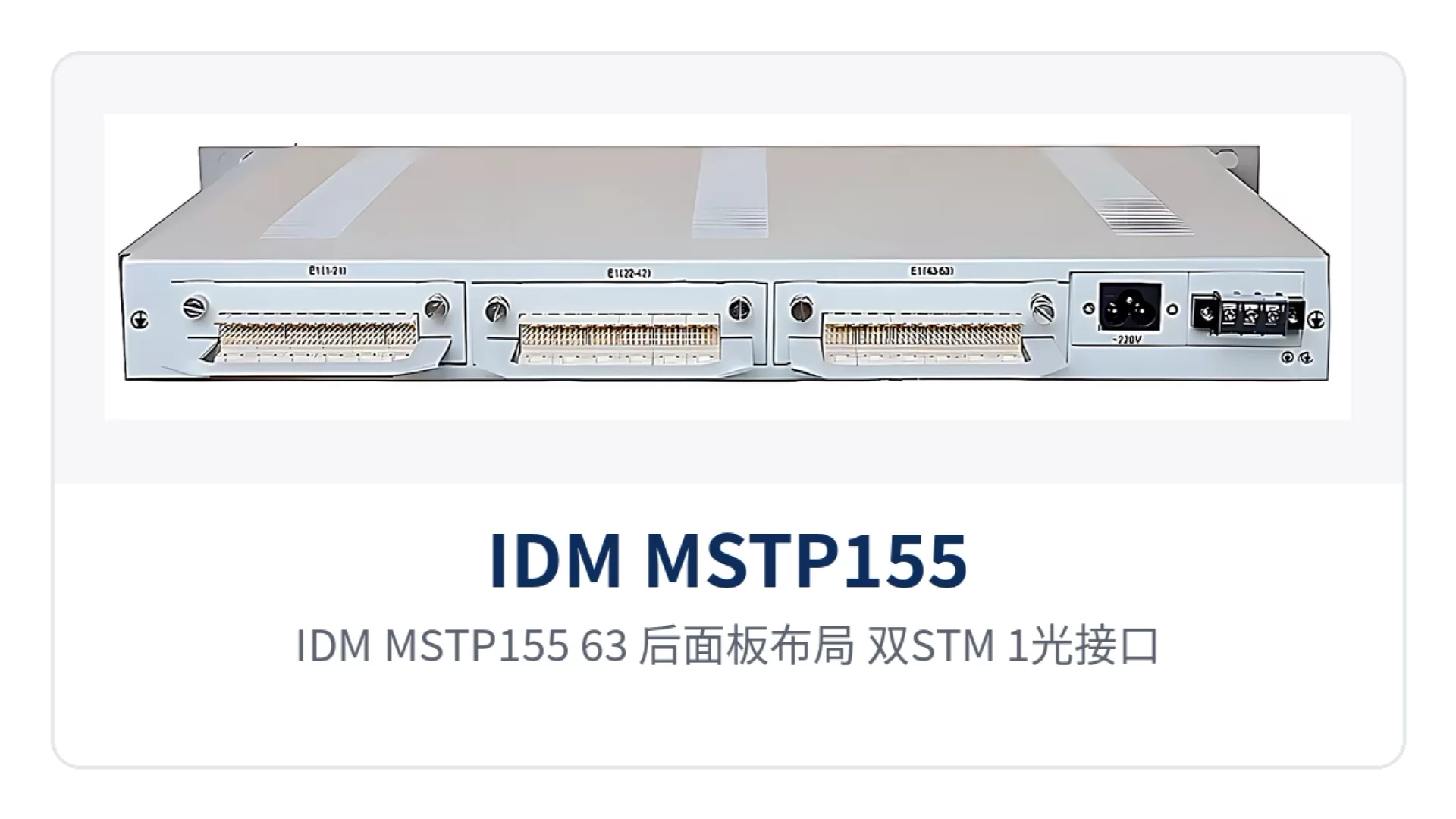
Figure 2: Rear panel layout of the IDM MSTP155-63, showing the dual STM-1 optical interfaces, 63-channel E1 high-density connectors, and the Ethernet and V.35 interface zones
The link margin of the optical interface is an item that must be calculated separately for long-station-spacing projects. With transmit optical power of -15 to -8 dBm and receiver sensitivity better than -32 dBm, the optical power difference left between the two ends can cover the attenuation of a 20 km single-mode link; when the station spacing exceeds this range, long-distance optical modules can be optionally installed to extend further without replacing the entire unit. On site, configure the modules at both ends as a pair of matching rate and wavelength, and cross-connect 1310 nm transmit with 1550 nm receive for intercommunication.
How to network with dual 155M optical ports
The platform supports three basic networking approaches: point-to-point, chain, and ring, and can also serve as a remote access node in joint networking with a centralized MSTP system. The topology is selected according to site distribution and fiber core resources; multiple approaches may coexist within the same private network, and each section determines its optical port connections and backup channel routing according to the actual optical cable route. As an SDH equipment manufacturer, Raytrans can assist in determining optical port connections and protection modes based on the actual site distribution of government private network optical fiber communication solutions and military emergency communications vehicle solutions.
- Point-to-point: one device at each end, with services directly connected over a single STM-1 optical path, suitable for service extension and protection between two equipment rooms.
- Chain: multiple sites connected in series, with intermediate sites adding/dropping E1 and Ethernet services locally, suitable for lines with evenly spaced stations along the route.
- Ring: sites form a ring end to end, with the two optical ports connected to the two directions of the ring respectively, so that when any section of optical cable is interrupted, services are rerouted along the other direction.
- Joint networking: serves as a remote access node connected to a centralized MSTP system, with services aggregated to the central end for unified dispatching and management.
In ring network deployment, the active and backup optical ports are connected to the two directions of the ring respectively, and 1+1 path protection ensures that external damage to a single optical cable affects only one side of the channel. After service switching, dispatch telephones and telecontrol E1 channels continue to operate; a chain line can also be built first and then formed into a ring, gradually transitioning to a ring network structure. In government private network optical fiber communication solutions and military emergency communications vehicle solutions, this SDH equipment can serve as an access and aggregation node for sites along the route.
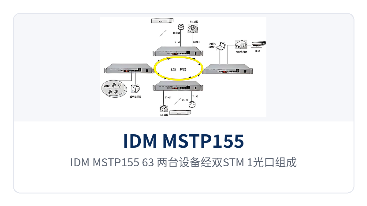
Figure 3: Topology diagram of two IDM MSTP155-63 units forming a ring network via dual STM-1 optical ports, with intermediate sites adding/dropping E1 services locally
Differentiated value
When selecting SDH equipment for a private network, the judgment points usually come down to three: how many services a single unit can carry, whether different services can be carried separately, and whether it can continue to operate under weak optical links and constrained power supply access. The table below lists the corresponding on-site value under four capability labels, so that procurement lists and acceptance documents can directly use the same set of wording, and it is also convenient for like-for-like comparison among multiple SDH equipment manufacturers.
| Differentiated capability | Value for private network users |
|---|---|
| Dual 155M aggregate links | Multi-service aggregation at a single node: two 155.52 Mb/s aggregate optical ports route traffic in two directions, with receiver sensitivity better than -32 dBm, so E1 and Ethernet services are still carried reliably over weak optical links |
| 63 E1 channels | 63 E1 channels add/drop multiplexed in one unit: as an ADM it adds/drops circuits in either direction, and one STM-1 covers all narrowband services of a medium-sized substation or a rail station |
| 4 isolated Ethernet channels | Secure isolation of private network services: 4 physically isolated Ethernet channels do not share bandwidth, so the surveillance network and the office network do not affect each other in the transmission segment |
| DC48V power supply | Plug-and-play for site upgrades: AC220V and DC 48V power supply formats are both available, and DC power from the communication panel and AC power from the equipment room share the same unit, with overall power consumption ≤50W |
The four capability labels correspond to four things: capacity, isolation, weak-light margin and power supply, and none of them can replace another. The aggregate side determines how far and how much service can be carried, the physical isolation on the Ethernet side determines whether service domains affect each other, and the power supply format determines whether a site upgrade needs an additional power supply module. Checking item by item against site conditions during design and quotation comes closer to actual operating results than a general comparison of unit parameters. SDH equipment manufacturers focused on optical transmission equipment, such as Raytrans, usually also provide a product showcase and configuration recommendations based on site conditions, making it easier for users to compare and select.
Typical Application Scenarios
In private networks, the dual 155M aggregate SDH transmission platform mostly sits at the boundary between the access layer and the aggregation layer, connecting upward to the transmission ring through STM-1 optical ports and downward to E1 equipment, Ethernet terminals and low-speed data devices. Different industries focus on different aspects of this link, and the three scenarios below are common landing points.
Substations and Power Supply Business Outlets of the Electric Power Private Network
Substations and remote power supply outlets have tight rack space, and a site may need to upload dispatch telephone, telecontrol E1 channels and the surveillance network at the same time, while fiber core resources are often only one or two. The platform fits into the communication panel in a 1U chassis, and the combination of 63 E1 channels and dual 155M aggregate links lets one unit aggregate all narrowband services of a site, while the surveillance and office networks run over Ethernet channels, so there is no need to deploy separate equipment for each service type.
The two aggregate optical ports connect to the two directions of the ring respectively, so when the inter-station optical cable is damaged by external forces, services are rerouted along the other side and the dispatch telephone and telecontrol channels are not interrupted. DC48V power supply can draw power directly from the DC busbar of the communication panel and is an alternative to AC power supply in the equipment room, so a site upgrade only needs to select one access mode according to the existing power conditions.
Stations along the Line and Section Equipment Rooms of Rail Transit
Stations along the line and section equipment rooms in rail transit differ greatly in service volume, and signal data, video surveillance and office networks have high continuity requirements, while different services must not affect each other on the transmission link. The platform uses 4 physically isolated Ethernet channels to carry signal monitoring, video and office services in separate domains, with each channel forwarded independently and not sharing bandwidth, so a traffic surge in one service type does not squeeze the channels of another.
Networking along the line usually starts as a chain and gradually forms a ring, and dual optical ports plus 1+1 path protection ensure that a single-segment optical cable failure on the ring does not affect services along the whole line. E1 channels carry existing signal and dispatch equipment, Ethernet channels carry newly added monitoring and video services, and the two sets of services run in parallel over the same optical path, reducing the number of devices and points of failure in the equipment compartment accordingly.
Cross-Region Links of Military and Government Private Networks
Equipment rooms of military and government private networks are far apart, fiber resources are limited, and some links have relatively high attenuation due to many splices and aging. Receiver sensitivity better than -32 dBm means a wider link budget margin, so reception remains stable under weak-light conditions and there is no need to lay new optical cables for every link during upgrades.
The existing transmission system of private networks is mainly SDH, and the platform can interconnect with the STM-1 optical interfaces of any standard SDH/MSTP equipment, so new nodes are accessed through standard optical ports without changing the original frame structure and service configuration. Network management functions support configuration, fault query and data statistics, and the command center can perform online real-time monitoring of the operating status of each node, reducing site-by-site inspection. For government private network optical fiber communication solutions and military emergency communications vehicle solutions, such SDH equipment can be installed directly in the communication panel or vehicle-mounted cabinet, working with optical transmission equipment to complete multi-service aggregation at the access layer.
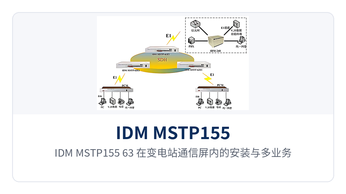
Figure 4: Installation and multi-service access schematic of the IDM MSTP155-63 in a substation communication panel
Conclusion
As a dual 155M aggregate SDH transmission platform, the IDM MSTP155-63E1 packs 63 E1 channels of add/drop multiplexing, 4 physically isolated Ethernet channels and 2 V.35/V.11 channels into a 19-inch 1U chassis; the two 155.52 Mb/s aggregate optical ports can route traffic in two directions or operate in active/standby mode, and 1+1 path protection keeps channels available on private network links when a single optical path fails.
Access-layer nodes of electric power private networks, rail transit and military and government private networks carry many service types but have limited rack space and fiber cores; one unit aggregates narrowband and broadband services at the same time, reducing the number of devices and points of failure on the site side accordingly. The specific optical module configuration, power supply format and service allocation should be determined after confirmation with the project service list and the SDH equipment manufacturer.