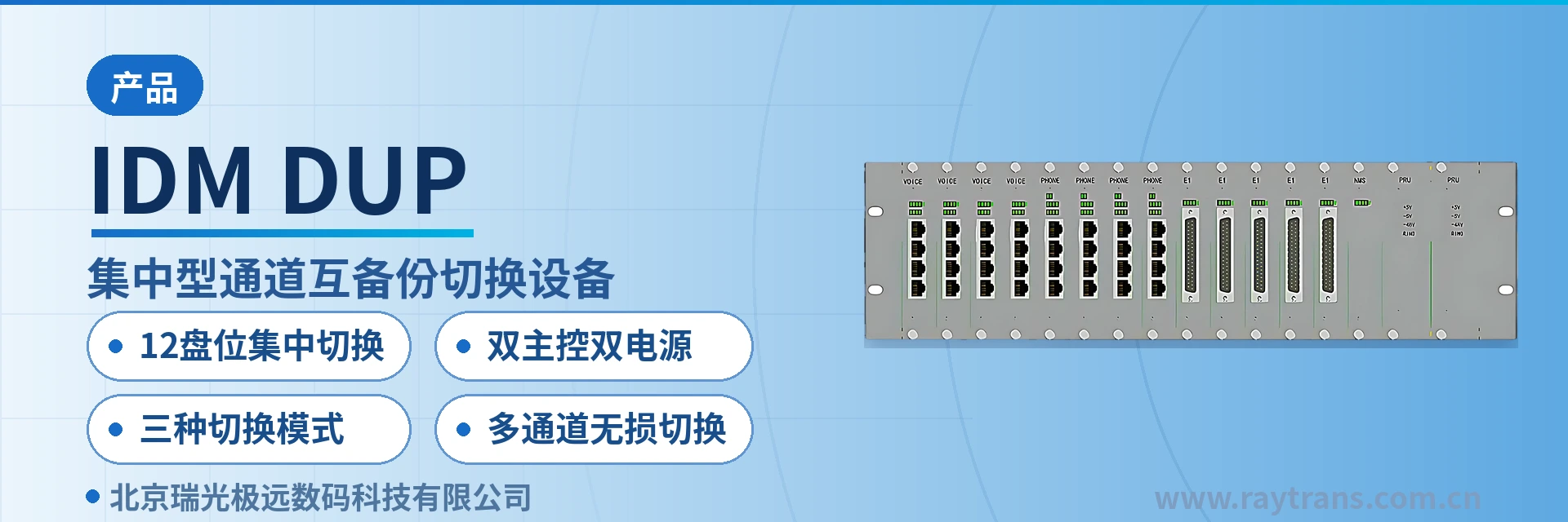
IDM DUP Centralized Channel Mutual Backup Switching Equipment
12 card slots mixed insertion 48 channels dual main control dual power supply hitless switching only when manual indicator light is on
Some important remote dispatch and control sites (such as subways, airports, and military) often require high system reliability and frequently use services over two or more transmission networks (for example, leasing channels from China Unicom and China Mobile separately, or mutual backup between satellite and terrestrial networks).
The IDM DUP centralized channel mutual backup switching equipment is a 3U centralized switching device developed by Beijing Ruiguang Jiyuan Digital Technology Co., Ltd. (Raytrans), used to feed the same service into two or more transmission networks simultaneously and automatically select the path with normal transmission at the receiving end. As a professional SDH equipment manufacturer and optical multiplexer manufacturer, Raytrans provides 12 mutual backup card slots in a centralized manner within the same chassis of this device, covering multi-path transmission and active optimal path selection transmission for E1 channels, telephone channels, pure audio channels, and RS232/RS485 channels, fully meeting the product showcase requirements of SDH equipment in multi-path transmission scenarios.
Places such as subway dispatch, airport operations command, and military remote command often lease channels from two carriers separately, or use satellite and terrestrial networks as mutual backup, so the same service is transmitted simultaneously over two or more links. Whether a link is interrupted is determined by the network side, while the subscriber terminal can only connect to one channel; if no device handles the switchover on the terminal side, the only option is for the duty operator to rewire at the cabinet. The centralized channel mutual backup switching equipment addresses exactly this terminal-side segment, and is widely used in scenarios such as subway dispatch channel mutual backup switching, military emergency communications vehicle solutions, and government private network optical fiber communication solutions.
The purpose of mutual backup channel switching is to reduce service interruption caused by transmission path failure or equipment failure. When a link degrades, the device judges and switches over to the normal path, and the dispatch console and telephone need not perceive the switchover process; the main control and power supply are further mutual backups, so the switching segment itself does not become a new single point. Raytrans's mutual backup channel switching equipment coordinates networking with SDH equipment, providing reliable assurance for various private network communication.
Key Specifications at a Glance: 12-slot centralized switching · dual main control and dual power supply · three switchover modes · multi-channel lossless switching · 3U chassis · unified Ethernet network management card
How many channels can 12 mutual backup card slots switch in a centralized manner?
The chassis of the centralized equipment provides 12 mutual backup switching card slot positions, with all service cards inserted in the same 3U chassis, and channel monitoring and switching uniformly performed by the Ethernet network management card. According to the channel definitions in the product documentation, each telephone mutual backup card and voice mutual backup card manages 4 channels, giving 48 channels when the 12 slots are at full configuration; each E1 lossy/lossless switching card has only two groups of E1 channel switching, giving 24 groups at full configuration.
The card slots are mixed insertion according to service needs, and telephone mutual backup cards, voice mutual backup cards, and E1 lossy/lossless switching cards can be configured simultaneously in the same chassis. Whichever service requires mutual backup and however many channels are needed, the corresponding number of service cards is configured; the number of channels increases or decreases with the card slots, unlike distributed solutions where a separate switching device is set up for each service type. This centralized mutual backup channel switching equipment performs channel selection and switchover functions in SDH transmission networks, and with SDH equipment can achieve automatic switching between primary and backup paths, making it a common companion product form for SDH equipment manufacturers in private network communication projects.
How do dual CMU main control cards and dual power cards as mutual backup eliminate single points of failure?
The chassis can provide dual CMU main control cards and dual power cards in mutual backup, with mutual backup relationships between the two main control cards and between the two power feeds; when a single main control card or a single power feed fails, services continue to be carried by the other. For places such as subway dispatch and military remote command that do not allow downtime, the redundancy level of main control and power supply affects continuous operation more than the number of channels. Taking subway dispatch channel mutual backup switching as an example, dispatch channels carry train command voice and data, and interruption directly affects operational safety; the redundancy design of dual main control and dual power supply is precisely the safety net for such scenarios.
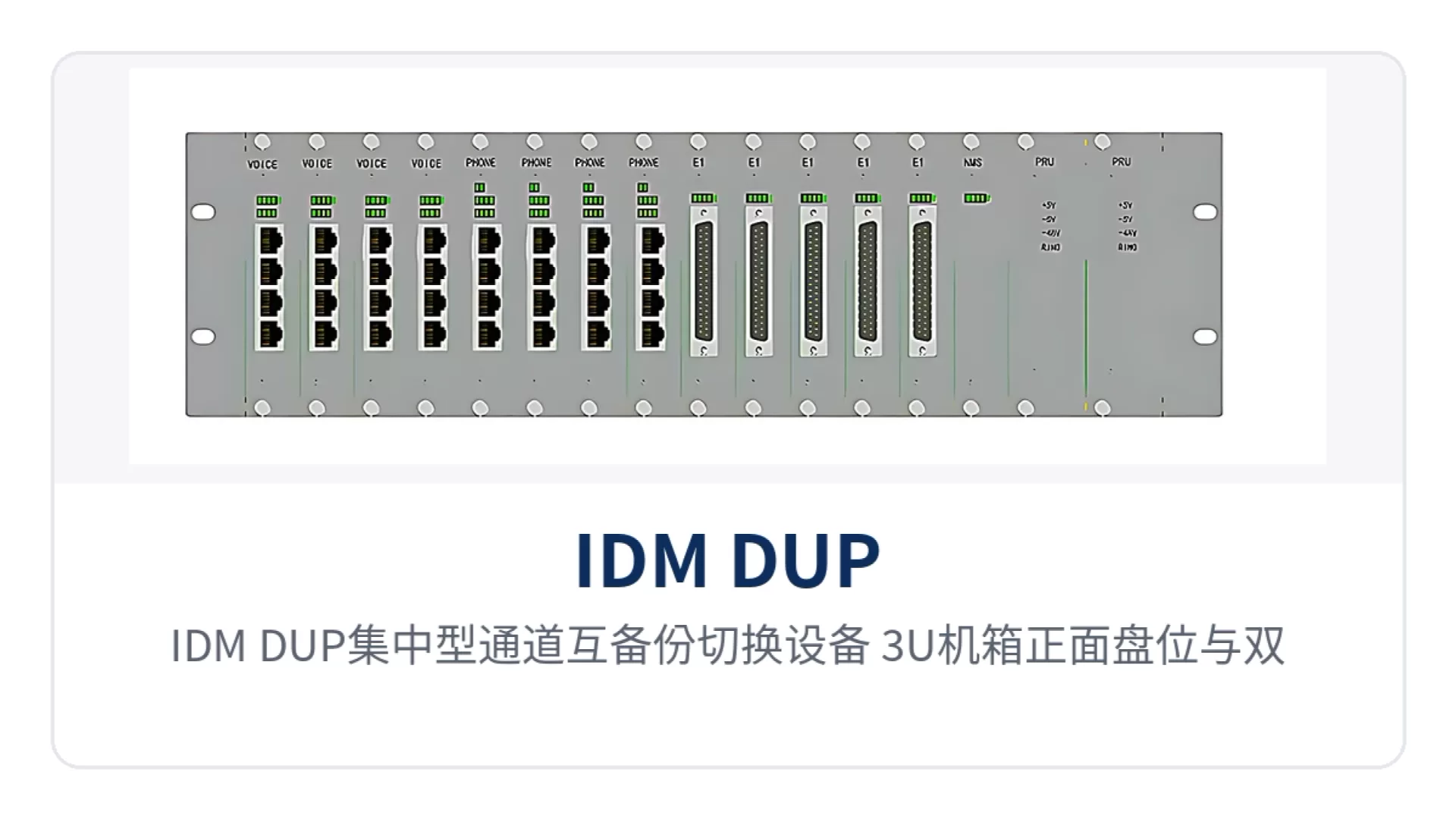
Figure 1: IDM DUP centralized channel mutual backup switching equipment 3U chassis front card slots and dual power cards appearance
The centralized equipment adopts a 3U architecture, with a unified Ethernet network management card in the chassis responsible for channel monitoring of each service card and issuing switching conditions. The operating status of all card slots is centralized in one place, and on-duty personnel can see on the network management which link each channel currently takes and which switchover mode it is in.
How many services do the telephone, voice, and E1 channel cards each manage?
The service cards of IDM DUP are divided by channel type; whichever card is inserted provides mutual backup and selection capability for that channel type, and the mixed-insertion chassis lets the same network management system manage telephone, audio, and E1 services simultaneously. The channel capacity and manual switching configuration of each card are listed in the following points; during configuration, select cards according to the number of on-site service channels.
- Telephone mutual backup card: for telephone channels, the 4-position DIP switch on the card controls manual switching of channels 1 to 4 respectively, and one card manages 4 telephone channels.
- Voice mutual backup card: for pure audio channels, the channel division is consistent with the telephone mutual backup card, likewise configured in groups of 4 channels.
- E1 lossy/lossless switching card: for E1 channels, one card has only two groups of E1 channel switching, configured in groups of 2 channels, with lossy and lossless card types.
How do the three switchover modes of automatic, network management, and manual coordinate?
Each user card slot supports three modes: automatic switchover, network management switchover, and manual switchover, and the current mode is indicated by the mode indicator light on the front panel. The mode can be set remotely by the network management system or changed on the spot with the mode switching button on the front panel, so both the equipment room and the site can operate it.
The division of labor among the three modes is automatic in normal times, remotely changeable, and locally forcible. Automatic switchover executes according to conditions preset by the network management system, requiring no on-duty operator intervention in daily operation; network management switchover is issued by on-duty personnel on the network management system; manual forced switchover can directly designate a channel via the network management system or the DIP switch on the card, and manual switching has higher priority. In government private network optical fiber communication solutions, this multi-mode coordination approach accommodates both daily automatic O&M and on-site forced dispatch during major events.
Why is manual forced switchover the prerequisite for lossless switching?
Lossless switching requires that service information not be lost before and after switching, and the device binds manual switching authority with mode status: only when the manual switching indicator light is illuminated is the manual switching of the DIP switch executed, so the switching action falls at a confirmable and predictable moment.
The 4-position DIP switch on each service card controls manual switching of channels 1 to 4 respectively, and the E1 switching card has only two groups of E1 channel switching. When a service needs to be fixed to a designated link according to the command relationship, first confirm that the manual switching indicator light on the service card is illuminated, then toggle the DIP switch of the corresponding channel.
What functions does the centralized channel mutual backup switching equipment provide?
The functions revolve around four main lines: splitting, detection and selection, three switchover modes, and network management monitoring, listed item by item in the table below for checking configuration against on-site service interfaces and O&M approach. The supply voltage, overall power consumption, and mechanical dimensions not listed in the table are subject to the manufacturer's technical documentation and are not a basis for acceptance on delivery.
| Function | Description |
|---|---|
| Multi-path transmission | The same service is fed into two or more transmission networks simultaneously; the number of channels is determined by the number of configured service cards |
| Active optimal path selection transmission | The receiving end judges the status of each channel and automatically selects the normally transmitting path for output |
| 12-slot centralized switching | The 3U chassis provides 12 mutual backup switching card slot positions, and switching of multiple channels is completed centrally in the same chassis |
| Dual CMU main control mutual backup | Dual CMU main control cards are mutual backups; when a single main control card fails, services continue to be carried by the other |
| Dual power card mutual backup | Dual power cards provide mutual backup power supply; a single power supply failure does not affect channel operation |
| Automatic switchover | Automatic switchover according to conditions preset by the network management system, requiring no manual intervention in daily operation |
| Network management switchover | Channel monitoring and switching are performed via Ethernet network management, with switching conditions set by the network management system |
| Manual forced switchover | A channel can be manually designated via the network management system or the DIP switch on the card, and manual switching has higher priority |
| Mode indication and control | The three modes of automatic, network management, and manual are indicated by panel indicator lights, and the panel button can switch modes |
| Lossless switching control | Manual switching is executed only when the manual switching indicator light is illuminated, and service information is not lost during switching |
Key Specifications and Performance Specifications
The architecture, card slot capacity, and switchover modes of the centralized equipment are listed item by item in the table below, with parameter definitions subject to the product documentation. Electrical and environmental specifications not given in the table are subject to the technical documentation supplied with the unit; during solution configuration, check against the items in the table and the number of on-site service channels.
| Item | Parameter/Specification | Description/Applicable Conditions |
|---|---|---|
| Device model | IDM DUP | Centralized channel mutual backup switching equipment |
| Chassis architecture | 3U centralized | Unified Ethernet network management card; service cards inserted in the chassis |
| Service card slots | 12 mutual backup switching card slot positions | Telephone cards, voice cards, and E1 switching cards mixed insertion, configured by number of service channels |
| Main control redundancy | Dual CMU main control cards mutual backup | Services uninterrupted when a single main control card fails |
| Power redundancy | Dual power cards mutual backup | A single power supply failure does not affect channel operation |
| Supported channel types | E1 channel, telephone channel, pure audio channel, RS232/RS485 channel | Select the corresponding service card by channel type |
| Channels per card | Telephone and voice cards 4 channels, E1 switching card 2 groups of E1 channels | The 4-position DIP switch on the card controls manual switching respectively |
| Switchover modes | Automatic switchover, network management switchover, manual switchover | Manual switching has higher priority |
| Switchover control | Network management sets switching conditions, panel button switches modes | Current mode indicated by panel indicator light |
| Network management interface | Unified Ethernet network management card | Channel monitoring and switching conditions issued uniformly |
| Power supply and power consumption | not yet recorded in the knowledge base | Subject to the manufacturer's technical documentation |
| Mechanical dimensions and operating environment | not yet recorded in the knowledge base | Subject to the manufacturer's technical documentation |
Differentiation Point
The three differentiated capabilities land on site as the concentration of card slots, the redundancy of the chassis, and the operating authority of switching, compared item by item in the table below. In the same configuration list, the number of card slots determines how many channels can be carried, and redundancy determines whether the chassis becomes a new single point.
| Differentiation Point | Customer Value |
|---|---|
| 12-slot centralized switching: multiple channels consolidated into one 3U chassis | 12 mutual backup card slots switch centrally, reducing service interruption caused by transmission path or equipment failure, and eliminating the need to set up a separate switching device for each service type in the equipment room |
| Dual main control and dual power supply: dual CMU main control cards and dual power cards mutual backup | Dual CMU main control cards and dual power cards mutual backup eliminate single points of failure and ensure service continuity |
| Three switchover modes: automatic, network management, and manual coexist | Automatic/network management/manual three switchover modes, with manual forced switchover having higher priority, using the same equipment in both peacetime and wartime states |
| Multi-channel lossless switching: telephone, voice, E1, RS232/RS485 configured by card | Multi-channel lossless switching; manual switching is executed only when the manual switching indicator light is illuminated, making switching actions controllable and traceable |
At the solution selection level, Raytrans, as an SDH equipment manufacturer and optical multiplexer manufacturer, can provide companion SDH equipment and product showcase around the IDM DUP centralized mutual backup channel switching equipment, and offer complete channel mutual backup configuration recommendations for scenarios such as military emergency communications vehicle solutions, government private network optical fiber communication solutions, and subway dispatch channel mutual backup switching, making it convenient for users to complete selection and solution interfacing within a unified product showcase system.
Typical Application Scenarios
The reason remote dispatch and control sites are equipped with centralized channel mutual backup switching equipment is that the services themselves must not fail along with a single link. During networking, one unit is configured at each end; the transmitting side feeds the same service into two links, the receiving side selects and outputs the optimal path according to channel status, and the two intermediate hops traverse different transmission networks. As a professional SDH equipment manufacturer, Raytrans provides complete mutual backup channel switching equipment solutions for such scenarios in its SDH product showcase.
Subway Dispatch Control
Subway dispatch carries the voice and data of train dispatch, power dispatch, and environment control dispatch, and multi-network redundancy is a routine requirement. Subways often lease channels from two carriers simultaneously, sending dispatch services to stations and depots via two networks respectively; the centralized channel mutual backup switching equipment centrally splits multiple services on the equipment room side, and the station side automatically selects and receives the optimal path according to channel status, achieving reliable assurance for subway dispatch channel mutual backup switching.
The 3U chassis is placed in the communications equipment room, with dual power cards and dual CMU main control cards in mutual backup, and the duty operator can see on the network management which link each channel takes. When there are many line stations, using one centralized device to carry multiple channels is easier to maintain uniformly than placing a separate switching device at each station.
Airport Operations Command
Airport operations command covers voice and public address for apron guidance, passenger services and ground support positions; interruption of any channel affects the pace of flight support. Airports usually have both a self-built transmission network and leased channels, with satellite links supplementing some scenarios; the centralized channel mutual backup switching device feeds the same service into two links simultaneously, and the receiver automatically selects the normal one.
The 12 card slots can be mixed in the same chassis with telephone mutual backup cards, voice mutual backup cards and E1 switching cards, so multiple services across the terminal, apron and operation control center share one network management system. Switchover conditions are set by the network management system according to support periods, and on-duty personnel do not need to confirm each unit at the cabinet.
Military Remote Command
Military remote command places high demands on redundancy and controllability, and often uses mutual backup between satellite and terrestrial networks to carry command telephone and dispatch data. In the military emergency communications vehicle solution provided by Raytrans, the centralized channel mutual backup switching device performs centralized splitting on the command post side, while the remote end selects the optimal channel for reception according to channel status, so command services stay on the normal path when link quality changes.
The need to designate channels according to the command relationship in combat readiness status is handled by manual forced switchover: it can be specified directly through the network management system or the DIP switches on the card, and manual switchover takes priority over automatic switchover. Dual CMU main control cards and dual power cards work in mutual backup, so the chassis does not drop out entirely on a single point of failure, and the command post no longer needs a separate backup device for the switchover stage.
Conclusion
As a centralized channel mutual backup switching device that packs 12 mutual backup card slots, dual CMU main control cards and dual power cards into a 3U chassis, IDM DUP places multi-path transmission, proactive selection and three switchover modes under one network management system, making it suitable for places such as subway dispatch control, airport operations command and military remote command where services must not fail with a single link. As an optical multiplexer manufacturer, Raytrans can provide complete SDH equipment selection support for government private network optical fiber communication solutions and military emergency communications vehicle solutions in its SDH product showcase.
Three things need to be confirmed clearly during selection: the channel types and number of channels to be mutually backed up on site, the number of links required, and whether switchover is led by automatic or manual operation. Channel type determines which service card is configured, the number of channels determines the number of card slots, and the switchover mode determines the network management conditions and DIP switch settings; once these three are settled, the chassis configuration and O&M division of work are settled as well.