IDM MULTI1000 Integrated Service Multiplexer
Five types of uplink heterogeneous automatic switchover, 10-slot mixed insertion of service and line cards, 24 E1 channels
With the mature development of information transmission technology, significant improvements have been made in terms of equipment size and cost performance. Therefore, in many application scenarios such as military, emergency management, air traffic control communication and navigation, oil, and various engineering sites, it will
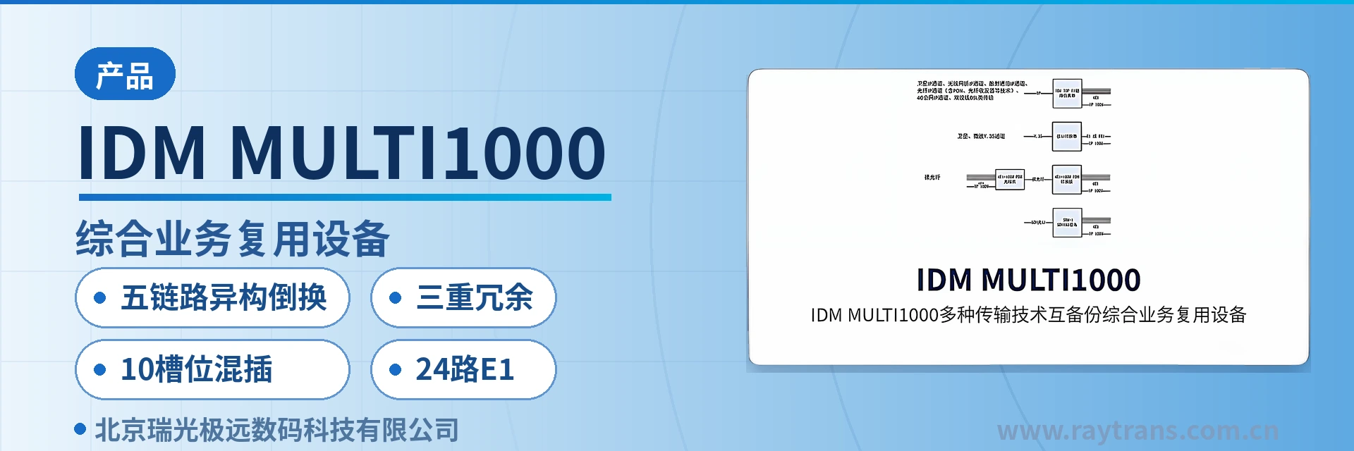
IDM MULTI1000 multi-link switchover integrated service multiplexer is an integrated service multiplexer developed by Beijing Ruiguang Jiyuan Digital Technology Co., Ltd. (Raytrans), combining multiple transmission technologies and multiple service access in one unit. It consists of an uplink access unit, a main control and clock unit, 10 undifferentiated I/O slots and various service access modules. It is used in military emergency communications, air traffic control communications and navigation, and oil and engineering sites to bring dozens of narrowband and broadband user services into the same device, and is a typical product showcase of an SDH equipment manufacturer and an optical multiplexer manufacturer for private network scenarios.
The design approach is to turn the various transmission channels readily available on site into uplink means for the same service access platform. The device can use an IP link, E1 link, bare fiber link, SDH link or wireless 4G link as the uplink transmission channel; when multiple links are configured, automatic protection switching can be performed between different types of uplink links, meeting the link reliability requirements of the military emergency communications vehicle solution and the government private network optical fiber communication solution.
Key specifications at a glance: 24 E1 channels · 4 Ethernet ports · 10 I/O slots · redundant power supply and main control board · automatic switchover among five types of uplink links · 1 node clock interface (ECK)
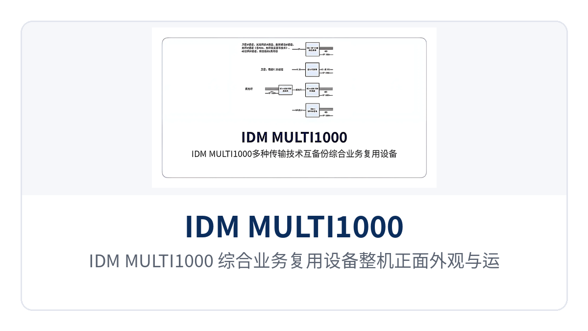
Figure 1: Overall front appearance and operating indicator LEDs of the IDM MULTI1000 integrated service multiplexer
What kind of device is a multi-link switchover integrated service multiplexer
A multi-link switchover integrated service multiplexer is an access layer device centered on multi-service access that backs up multiple transmission technologies with each other: one side faces the on-site user service interfaces, and the other side multiplexes services into IP, E1, bare fiber, SDH or 4G channels for transmission. When two or more uplink links of different types are configured, the links can switch over automatically. As an access product of the SDH equipment manufacturer Raytrans, the device is often used in multi-service access scenarios in the product showcase.
The modular structure lets service access and line access share the same set of slots, so a site can be commissioned by inserting modules according to the service list. When service types or capacity change, replacing or adding the corresponding modules adapts to the new requirements, while the chassis and existing modules continue to be used.
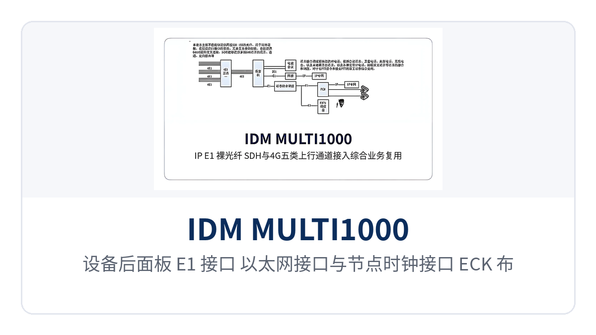
Figure 2: Close-up of the cabling area for E1 interfaces, Ethernet interfaces and the node clock interface (ECK) on the rear panel
What types of common uplink transmission channels are there
The uplink channels the device can connect to fall into five types, each with different bandwidth conditions and acquisition methods, which can be combined and configured on site accordingly.
IP-type transmission: satellite IP channels, wireless bridge IP channels, troposcatter communication IP channels, optical fiber IP channels (including PON, media converter and other technologies), 4G public network IP channels and twisted pair DSL-type transmission.
E1 channels: usually provided by PDH optical multiplexers, microwave equipment and DSL equipment, or other E1 channels leased from a carrier.
V.35 broadband channels: usually provided by satellite or microwave channels, with bandwidth less than the width of one E1.
SDH channels: usually optical port or electrical port, with a common bandwidth of 155.52Mbit/s, i.e. the STM-1 interface, so services of SDH equipment from different vendors can interoperate.
Bare fiber channels: usually 4E1 plus wire-speed 100M Ethernet PDH optical multiplexers are used to transmit services.
Why do military and other scenarios first emulate IP channels into E1
Military and other sites need to add encryption devices on E1 transmission channels. A common practice is to first use TDM over IP equipment to emulate an E1 channel over the IP network, and then connect it to the integrated service multiplexer. This approach is also reflected in Raytrans' military emergency communications vehicle solution.
The IDM TOP series IP line emulation equipment features high clock accuracy and the ability to provide stable framed E1 output when the bandwidth is insufficient to emulate one E1 channel, so that IP uplink links can also meet the access requirements for adding encryption devices.
How is heterogeneous automatic switchover among five types of uplink links implemented
Heterogeneous automatic switchover only considers whether a link can normally transmit services, and does not require the backup link to be of the same type as the primary link. The device implements heterogeneous automatic switchover among five types of uplink links—IP/E1/bare fiber/SDH/4G—and services pass as long as any one link is normal. This capability is the core feature of the multi-link switchover integrated service multiplexer and also serves scenarios with high link reliability requirements such as the government private network optical fiber communication solution.
Links participating in switchover: IP links, E1 links, bare fiber links, SDH links and wireless 4G links.
Switchover trigger condition: when the uplink link currently carrying services is interrupted or cannot normally transmit services, the services are carried by the remaining available links.
Switchover scope: services switch between links of different types, and the backup link is not required to be of the same type as the primary link.
Relationship with redundancy: transmission link redundancy, together with power supply redundancy and main control board redundancy, forms full-system redundancy, and the three types of redundancy can be configured at the same time.
Automatic switchover among five types of uplink links solves the problem of inconsistent channel sources on site: vehicle-mounted sites often have both 4G channels and satellite IP channels, fixed sites have bare fiber or SDH, and leased lines are mostly E1. With these channels connected in parallel to the same device, services can be carried as long as any one is normal, so the path is not lost due to the interruption of a single channel.
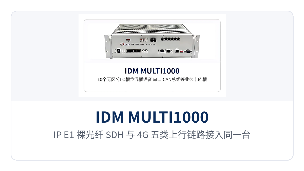
Figure 3: Networking diagram of IP, E1, bare fiber, SDH and 4G uplink links accessing the same device
How are 24 E1 channels accessed
How 24 E1 channels are accessed is implemented directly according to the interface list: the device provides 24 E1 interfaces, 4 Ethernet interfaces (FE1, FE2, FE3) and 1 node clock interface (ECK). The 24 E1 channels can be used to carry narrowband services such as voice channels, audio and low-speed data.
E1 channels can be obtained flexibly: they can be provided by PDH optical multiplexers, microwave equipment and DSL equipment from PDH optical multiplexer manufacturers, or other E1 channels leased from a carrier. After services enter the device, they are allocated by channel and time slot to the 24 E1 interfaces for output, so a single device can concentrate and multiplex voice channels and data scattered in various directions onto the uplink channels.
During on-site configuration, first count the number of voice and data channels required in each direction, then check the time slot occupation of each E1, and determine the clock source of the node clock interface as well. Voice goes through FXO/FXS, magneto telephone or hotline phone service cards, and low-speed data goes through G.703 codirectional 64K, RS232/RS485 and other service cards, allocated to the corresponding directions by number of channels.
Which service cards can be inserted into the 10 I/O slots
Which service cards can be inserted into the 10 I/O slots—the answer is that these slots do not distinguish between service and line, and the same set of slots can hold either user service modules or line modules. The 10-slot mixed insertion supports dozens of narrowband and broadband services; when the service list changes, replacing or adding the corresponding modules is sufficient, making it convenient to combine as required in the product showcase.
Voice type: FXO/FXS, 2-wire/4-wire audio (E&M), magneto telephone, hotline phone and other voice channel services.
Data type: asynchronous/synchronous RS232, asynchronous and synchronous RS422, RS485, V.21, V.22, V.24, V.34, V.35, G.703 codirectional 64K.
Interface and bus type: 10/100BASE-T Ethernet, on/off signal, CAN bus.
During on-site card configuration, first count the number of channels of each interface type according to the site service list, then check the occupation of the 10 I/O slots and reserve slots for subsequent capacity expansion. The same chassis can be assembled into a voice-oriented configuration or a configuration dominated by serial ports, on/off signals and Ethernet, and spare parts are common among sites.
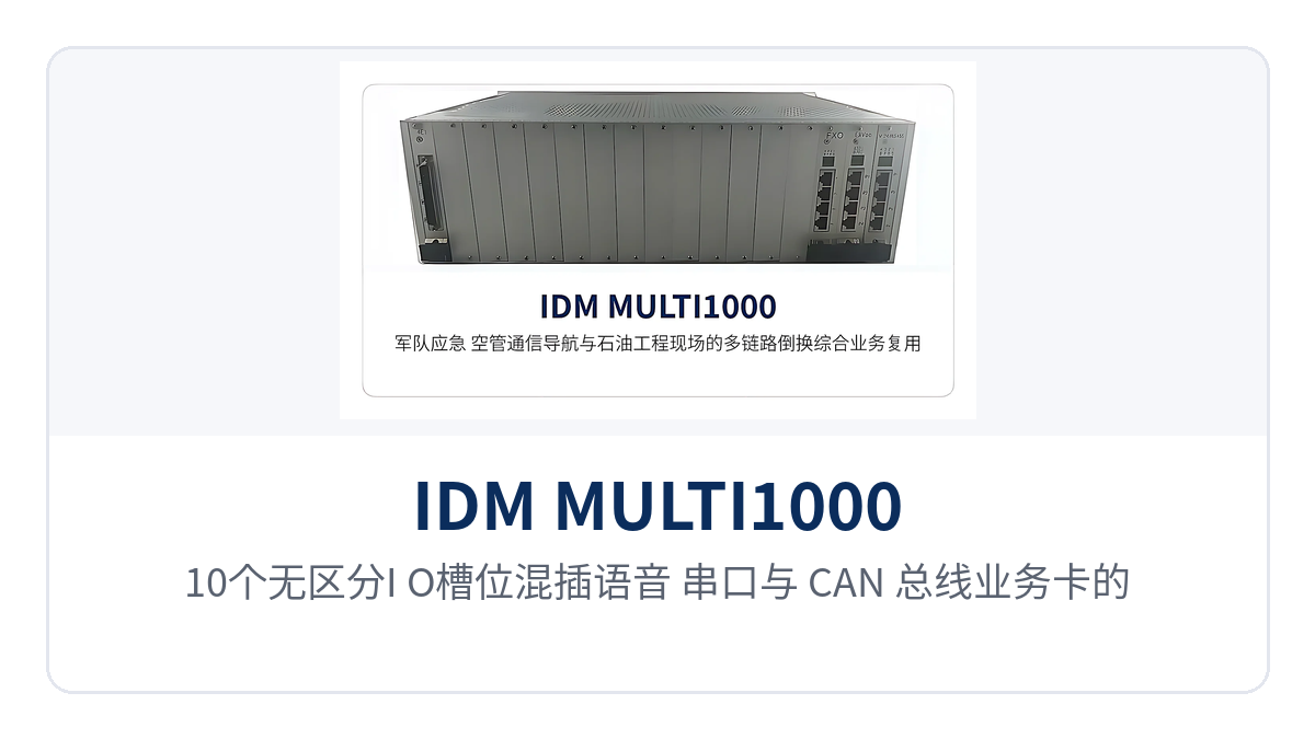
Figure 4: Close-up of the slot layout with 10 undifferentiated I/O slots mixing voice, serial port and CAN bus service cards
What parts does the full-system triple redundancy include
IDM MULTI1000 can be optionally equipped with full-system redundancy (power supply/main control board/transmission link), so services are not interrupted by a single link failure. The three types of redundancy correspond to the three links of power supply, control and transmission. Raytrans can optionally provide this redundancy configuration as required in the government private network optical fiber communication solution and the military emergency communications vehicle solution.
Power supply redundancy: power supply modules are configured redundantly, and when one power supply is abnormal, the other continues to supply power.
Main control board redundancy: main control boards are configured redundantly, and when the main control unit is abnormal, services are continued by the standby main control unit.
Transmission link redundancy: multiple uplink links can be configured at the same time, with automatic protection switching between links.
The three types of redundancy—power supply, main control board and transmission link—can be configured at the same time, so services are not interrupted by a single point of failure. For unattended engineering sites and emergency communications sites, this design is the main means of reducing site visits and shortening failure recovery time.
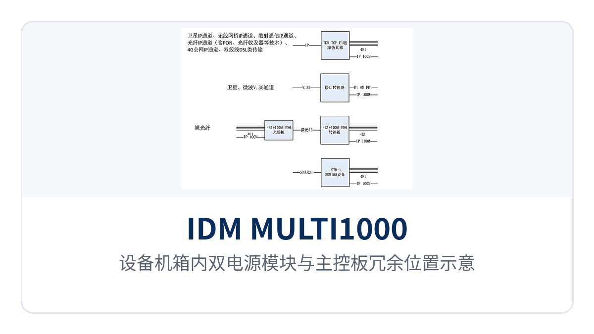
Figure 5: Schematic of the positions of the dual power supply modules and redundant main control boards in the chassis
How are network management and online self-test used
The optional network management functions automatically load network-wide configuration information, allow configuration of port parameters and support loopback detection; on-duty personnel check the port status and channel conditions of each site at the central side without visiting each site to check the configuration.
The device supports inserting self-test signals to check channel transmission conditions, assisting device commissioning and routine maintenance. The installation and maintenance phase also supports transmission over long-latency satellite links, with satellite links such as E1, V.35 or Ethernet selectable, so services can be carried normally even when satellite channel latency is relatively high.
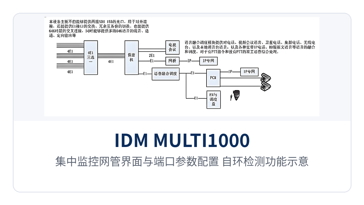
Figure 6: Schematic of the centralized monitoring network management interface with port parameter configuration and loopback detection functions
Core functions and performance parameters
IDM MULTI1000 concentrates multiple transmission link access, multi-service multiplexing and centralized monitoring in the same chassis. The functions and their purposes are shown in the table below.
Function | Description |
|---|---|
Five uplink types | An IP link, E1 link, bare fiber link, SDH link or wireless 4G link can be selected as the uplink transmission channel |
Heterogeneous automatic switchover | When multiple links are configured for uplink, automatic protection switching is performed between different types of uplink links, and service signal transmission is ensured as long as any one link is normal |
System-wide redundancy | Optional power supply redundancy, main control board redundancy and transmission link redundancy; the three types of redundancy can be configured simultaneously |
Multi-service access | Optional services such as FXO/FXS, 2-wire/4-wire audio (E&M), asynchronous/synchronous RS232, asynchronous and synchronous RS422, RS485, 10/100BASE-T, V.21, V.22, V.24, V.34, on/off signal, CAN bus, magneto telephone, hotline phone, V.35 and G.703 codirectional 64K |
Slot expansion | Modular design; the 10 I/O slots do not distinguish between service and line, meeting current application and subsequent expansion requirements |
Centralized monitoring | Optional network management functions; automatically loads network-wide configuration information, allows configuration of port parameters and supports loopback detection |
Satellite link adaptation | Supports transmission over satellite links with large latency; satellite links such as E1, V.35 or Ethernet can be selected |
Online self-test | A self-test signal can be inserted to check channel transmission status and assist in device commissioning and maintenance |
Interface configuration | 4 Ethernet interfaces (FE1, FE2, FE3), 1 node clock interface (ECK) and 24 E1 interfaces |
Interface and capability parameters are listed in the table below. The parameters are subject to the product documentation, and the specific configuration is determined according to the project service list.
Item | Parameter/Specification | Description/Applicable Conditions |
|---|---|---|
Uplink transmission link | Five types: IP, E1, bare fiber, SDH and wireless 4G | Optional according to the channels available on site; can be used standalone or in combination |
Link switchover | Automatic protection switching between different types of uplink links | Takes effect when two or more links are configured for uplink; services can be transmitted as long as any one link is normal |
Redundancy configuration | Power supply redundancy, main control board redundancy and transmission link redundancy | Optional configuration, determined according to the project reliability requirements |
E1 interface | 24 channels | Carries narrowband services such as voice channels, audio and low-speed data |
Ethernet interface | 4 (FE1, FE2, FE3) | Used for 10/100BASE-T service access |
Node clock interface | 1 (ECK) | Used for node clock interconnection |
I/O slots | 10, without distinguishing between service and line | Modular plug-in cards, supporting dozens of narrowband and broadband services |
Service type | FXO/FXS, 2-wire/4-wire audio (E&M), RS232, RS422, RS485, 10/100BASE-T, V.21, V.22, V.24, V.34, on/off signal, CAN bus, magneto telephone, hotline phone, V.35, G.703 codirectional 64K | Modules are selected according to the site service list |
IP link emulation | An IP channel can be emulated as an E1 channel before access | Suited to sites where encryption equipment needs to be added on the E1 channel |
Satellite link | Supports transmission over satellite links with large latency | Satellite links such as E1, V.35 or Ethernet can be selected |
Centralized monitoring | Optional network management functions | Automatically loads network-wide configuration information, port parameters are configurable and loopback detection is supported |
The correspondence between the three differentiated capabilities and the on-site value is shown in the table below.
Selling Point | Value on Site |
|---|---|
Five-link heterogeneous switchover: automatic heterogeneous switchover among IP, E1, bare fiber, SDH and 4G | Any link that is up keeps traffic flowing; switchover does not require the backup link to use the same format as the primary link, so networking works even when channel sources are not uniform |
Triple redundancy: power supply, main control board and transmission link | The three types of redundancy can be ordered together; services are uninterrupted on a single point of failure, reducing site visits for unattended sites |
10-slot mixed insertion: 10 undifferentiated I/O slots | 10 undifferentiated I/O slots take dozens of narrowband and broadband service cards; capacity expansion needs no new enclosure, and spare parts are common across sites |
24 E1 channels: 24 E1 channels plus 4 Ethernet interfaces in a standalone unit | One device carries voice channels, audio and low-speed data at the same time, so a hub site does not need a separate unit for each service type |
Typical Application Scenarios
IDM MULTI1000 targets sites with mixed channel types and a wide variety of services; five-link heterogeneous switchover and system-wide triple redundancy are the basis for its role as access-layer transmission in these scenarios. Across the following three industry orientations, the differences in device configuration lie mainly in which uplinks are accessed and which service cards are inserted.
How to Build a Network at a Military Emergency Communications Site
The uplinks of military emergency communications often change with the mission: bare fiber may be available in the camp, a vehicle-mounted state relies on wireless 4G, and remote areas need satellite IP channels. IDM MULTI1000 accesses these channel types at the same time and automatically switches over after multiple uplinks are configured, so any link that is up continues to carry command voice and critical data.
When a cryptographic device needs to be added on an E1 channel, a TDMoIP device can first emulate the IP channel as E1 before access; power redundancy and main control board redundancy provide backup at the power supply and main control levels for a temporary command post. In a military emergency communications vehicle solution, SDH links, 4G and satellite channels can be online at the same time, and on-site service cards can be added or removed as required to achieve rapid commissioning of multiple services.
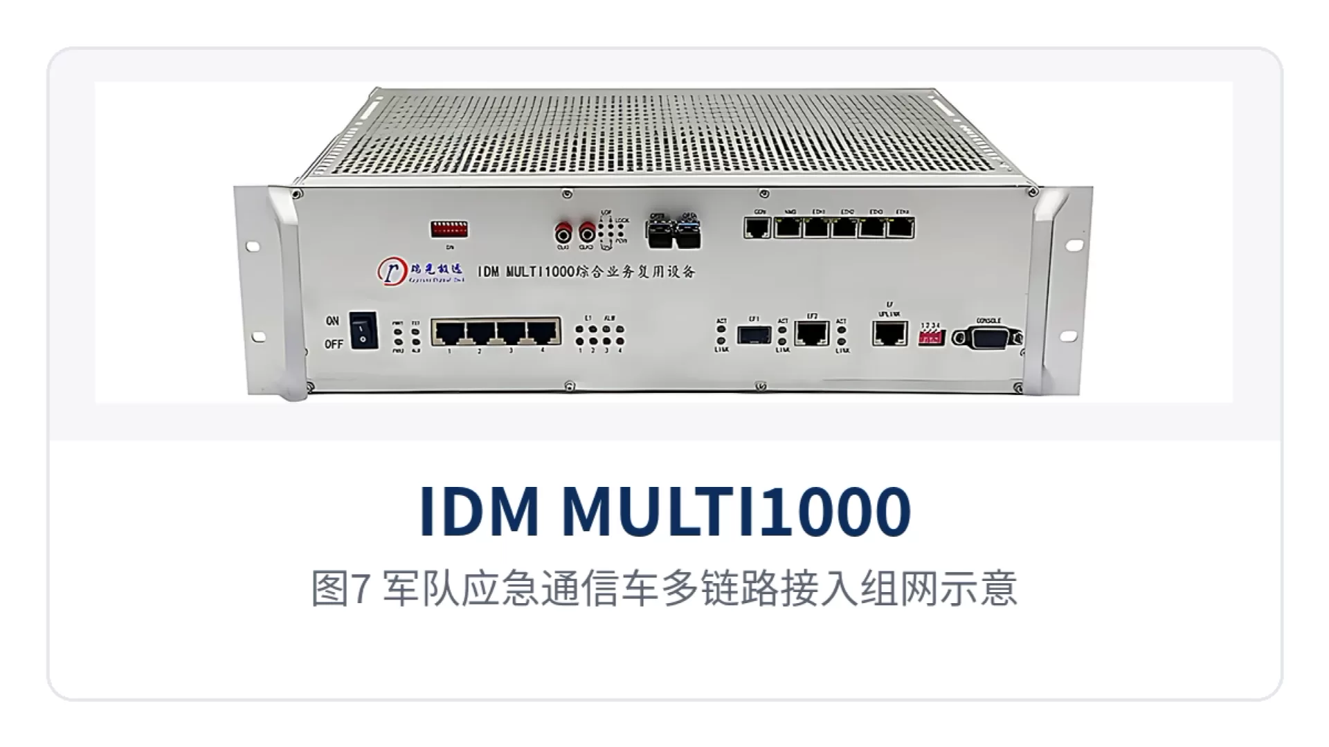
Figure 7: Multi-link access networking schematic for a military emergency communications vehicle
How to Configure an Air Traffic Control Communication and Navigation Site
Services at an air traffic control communication and navigation site are mainly voice and low-speed data, with many interface types and channels under different ownership. IDM MULTI1000 uses 24 E1 channels plus 4 Ethernet interfaces to carry such multiple services, and one device completes the access and multiplexing of voice channels, audio and data; E1 channels can be provided by PDH optical multiplexers or microwave equipment, or leased from a carrier.
Air-ground calls and navigation data demand high channel continuity, and five-link heterogeneous switchover leaves the site one more available channel beyond the existing ones. The optional network management function automatically loads network-wide configuration information and supports configuration and loopback detection of port parameters, making it easy for on-duty personnel to track channel status at each site from the central side.
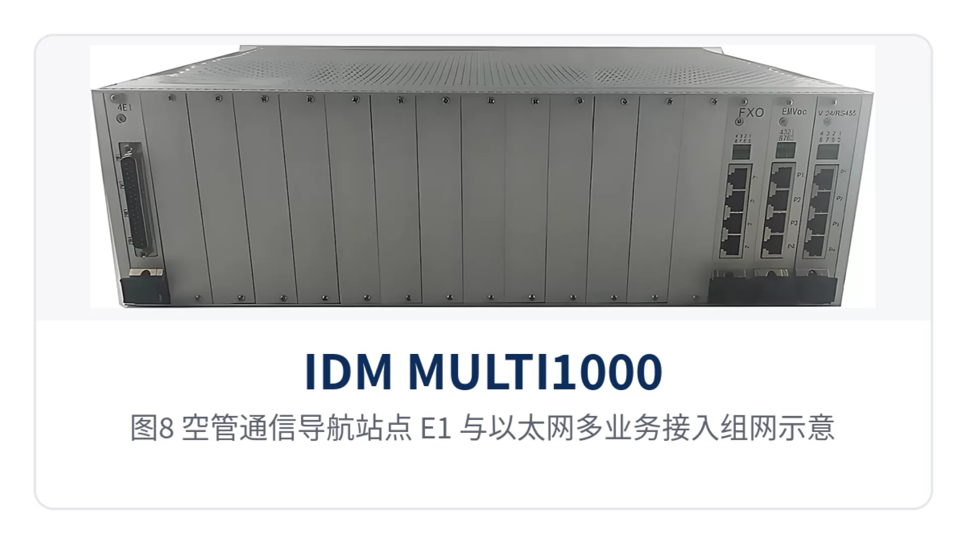
Figure 8: E1 and Ethernet multi-service access networking schematic for an air traffic control communication and navigation site
How to Use Unattended Sites in Oil and Engineering Fields
Sites in oil and engineering fields are often scattered in the field, with unstable power supply and channel conditions. IDM MULTI1000 supports transmission over high-latency satellite links and can select satellite links such as E1, V.35 or Ethernet; even when satellite is used as the uplink channel with relatively high latency, services can still be carried.
The five channel types of IP, E1, bare fiber, SDH and 4G can be combined according to on-site conditions, and any link that is up keeps traffic flowing. 10 undifferentiated I/O slots take dozens of narrowband and broadband service cards, so the same batch of equipment adapts to the service list of different sites; during capacity expansion, modules can be replaced or added without changing the enclosure.
Figure 9: Satellite and optical fiber hybrid networking schematic for unattended sites in oil and engineering fields