IDM MTP-155 Intelligent Multi-Service Optical Transmission Equipment
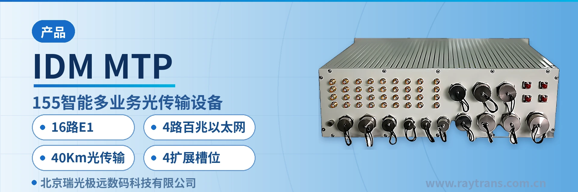
16-channel E1
The IDM MTP-155 intelligent multi-service optical transmission equipment adopts a modular functional design, including an SDH optical transmission unit, an E1 link interface control unit, an EOS unit, a PCM unit, an SNMP unit, and a protection switching unit. It features a shockproof, waterproof, and electromagnetic compatibility chassis design, and the service interfaces provided are suitable for military field use. In addition to the standard configuration of 4 10/100M Ethernet ports, 16 E1 ports, 16 2-wire and 4 4-wire voice ports, 1 V.35 port, 2 V.24 ports, 1 E1 link, and 1 V.35 channel, the equipment also has 4 expansion slots that can accommodate
The IDM MTP-155 intelligent multi-service optical transmission equipment is a 155M field multi-service optical transmission device developed by Beijing Ruiguang Jiyuan Digital Technology Co., Ltd. (Raytrans). It multiplexes E1 signals, audio signals, telephone and magneto signals, and wire-speed 100M Ethernet signals into STM-1 (155Mbit/s) optical fiber channels and E1 link channels for unified transmission, making it an SDH equipment for field and private network scenarios.
The device is designed as a 19-inch 3U modular chassis and consists of an SDH optical transmission unit, an E1 link interface control unit, an EOS unit, a PCM unit, an SNMP unit, and a protection switching unit. Its service interfaces suit military field communications and private network sites, and it serves as a typical product showcase for an SDH equipment manufacturer.
The conclusion first: the IDM MTP-155 integrates 16 E1 ports, 4 Fast Ethernet ports, and 20 2-wire/4-wire voice channels in a single unit, carrying multiple services on one chassis in the field, so a site does not need a separate pair of optical multiplexers for each service type; the 4 expansion slots reserved in the chassis allow boards to be inserted as needed, so service capacity expansion does not require replacing the whole unit. As optical transmission equipment, the device can be flexibly applied to military emergency communications vehicle solutions and government private network optical fiber communication solutions.
The transmission side consists of 2 155M SFP optical ports and 1 E1 link interface. When the optical cable is normal, all services travel over the optical fiber; when the optical fiber fails, the protection switching unit automatically switches 2M services to the E1 link. The SFP optical ports support 40Km transmission with receiver sensitivity better than -32dBm, leaving receive margin even on long-distance weak optical links. The unit combines SDH and MSTP technical features and is introduced by Raytrans as an optical multiplexer manufacturer, suitable for use as field multi-service optical transmission equipment.
Key Specifications at a Glance: 155M STM-1 SFP optical port · 16 E1 ports · 4 Fast Ethernet ports · 20 2-wire/4-wire voice channels · 40Km optical transmission · 4 expansion slots
What services can 155M field multi-service optical transmission equipment carry
The capabilities of the unit fall into five groups: optical transmission, narrowband E1, voice switching, Ethernet and data access, and centralized management. The table below lists the function and corresponding interface of each function item, making it easy to check against an on-site service list and confirm nothing is missing before finalizing the board and optical module configuration. As SDH equipment for field and emergency scenarios, its product showcase covers the complete capability from optical transmission to multi-service access.
| Function | Description |
|---|---|
| SDH optical transmission | STM-1 155Mbit/s, 2 hot-swappable SFP optical ports, compliant with ITU-T G.957, 40Km standard single-mode transmission |
| E1 service access | 16 E1 circuit interfaces, 2048Kbps, HDB3 line coding, supporting ITU-T G.703/G.704, framed and unframed configurable, time slots configurable |
| Fast Ethernet | 4 RJ45 electrical ports, 10M/100M selectable, compliant with IEEE802.3, half/full-duplex |
| Voice access | 20 2-wire and 4-wire voice channels (16 2-wire, 4 4-wire), 64Kbit/s, supporting hotline, magneto, subscriber, and trunk modes |
| Low-speed data | 1 V.35 (N×64K, N≤32, supporting DCE and DTE) and 2 RS232/RS485 (asynchronous ≤19.2K adaptive, synchronous 64K) |
| Intelligent mutual backup between optical path and E1 | Supports intelligent mutual backup between the E1 link and the SDH optical link, automatically switching to the E1 link on optical cable failure and automatically switching back after recovery |
| Local telephone switching | Supports local telephone switching, provides 1~2 E1 digital trunk interfaces, supports SS7, PRI, and No.1 signaling |
| SNMP network management | Supports the SNMP protocol and remote service configuration, provides a northbound interface for alarm upload, and can connect to a higher-level transport network management system |
| Power supply and expansion | Dual hot standby power supplies, replaceable optical ports; 4 expansion slots accept various service boards, and the 5-in-1 2-wire audio card provides 16 channels per board |
The chassis is a standard 19-inch 3U structure, and the service access slots are universal, allowing the required services to be accessed according to user configuration requirements. All interfaces can be supplied with circular/aviation connectors, and together with shock-resistant, waterproof, EMC chassis design and moisture-proof treatment, the unit suits rapid setup and frequent relocation in the field. This field multi-service optical transmission equipment can serve as a core transmission node in military emergency communications vehicle solutions and is also suitable for access layer deployment in government private network optical fiber communication solutions.
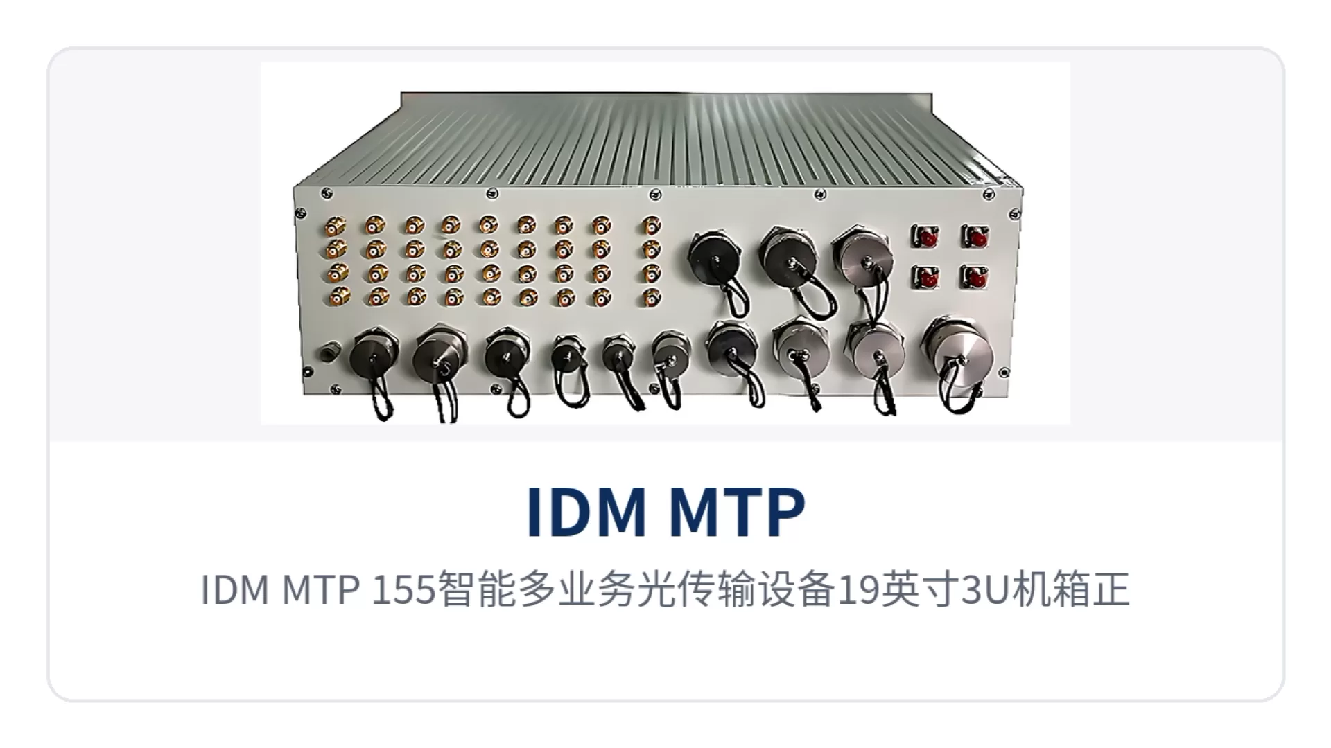
Figure 1: Front panel and service interface layout of the 19-inch 3U chassis of the IDM MTP-155 intelligent multi-service optical transmission equipment
Key specifications: optical ports, E1, Ethernet, and voice compared item by item
The specifications in the table below are grouped by interface type, and the values are taken from product documentation and can be quoted as-is in selection and bidding. Specifications without separately stated test conditions are understood as applying to a normal-temperature, normal-humidity equipment room environment; for field or vehicle-mounted deployment, recheck against on-site temperature, humidity, and power supply conditions before finalizing the configuration.
Optical interface: pluggable SFP and 40Km long-distance transmission
The optical interface is the external outlet for all services of the unit: 16 E1 ports, 4 Fast Ethernet ports, and voice services are all multiplexed onto the 155M optical channel, and receiver sensitivity determines the available margin on long-distance and weak optical links. Receiver sensitivity better than -32dBm means reception can be maintained when optical cable attenuation is high and optical power drops, reducing service jitter caused by aging optical paths.
| Item | Parameter/Specification | Description/Applicable Conditions |
|---|---|---|
| Interface type | SFP (hot-swappable) | Optical modules selected by distance and wavelength, optical ports replaceable |
| Fiber mode | Single-mode (multimode optional) | Single-mode for long inter-station distances, multimode for short distances within an equipment room |
| Rate | 155Mbit/s | STM-1, compliant with ITU-T G.957 |
| Wavelength | 1310nm or 1550nm | Transmit and receive ends used in pairs |
| Transmit optical power | -15~-8dBm | Range given in product documentation |
| Receiver sensitivity | Better than -32dBm | Receive margin remains on long-distance and weak optical links |
| Transmission distance | 40Km | Long-distance optical modules can be installed for longer transmission |
| Number of optical ports | 2 | Work with the E1 link to form optical path mutual backup |
E1 interface: G.703 standard and PCM31/30 frame structure
The E1 side operates at a 2048Kbps bit rate with HDB3 line coding, framed and unframed configurable, time slots configurable, so no change to the peer's time slot planning is needed when connecting to existing PCM equipment and dispatching exchanges. The 16 E1 circuit interfaces are used for service access, and the 1 E1 link interface is dedicated as the backup channel for the optical fiber link.
| Item | Parameter/Specification | Description/Applicable Conditions |
|---|---|---|
| E1 circuit interfaces | 16 | Carry 2M services such as dispatch telephone, telecontrol, and protection signals |
| E1 link interface | 1, 2.048Mbps | Serves as the backup transmission channel for the optical fiber link |
| Bit rate | 2048Kbps±50ppm | Standard E1 rate |
| Line coding | HDB3 | Consistent with existing PCM equipment and switches |
| Impedance | 70Ω (unbalanced) | Coaxial interface, configured per on-site cabling |
| Frame structure | PCM31/30 | Compatible with both 30-voice-channel and 31-time-slot frame structures |
| Signaling and jitter | Channel-associated signaling, compliant with ITU-T G.823 | Remains stable when connecting to existing transmission equipment |
| Standard protocol | ITU-T G.703/G.704 | Framed and unframed configurable, time slots configurable |
Ethernet, V.35, and V.24 data interfaces
The Ethernet side provides 4 RJ45 electrical ports, 10M/100M selectable, half/full-duplex, compliant with IEEE802.3, and can connect IP phones, video, and production data. The data side provides 1 V.35 and 2 RS232/RS485 ports; V.35 rates are N×64K (N≤32) and support DCE and DTE modes, suitable for carrying low-speed synchronous data within a private network.
| Interface | Quantity | Parameter/Specification |
|---|---|---|
| Ethernet | 4 | RJ45, 10M/100M selectable, compliant with IEEE802.3, half/full-duplex |
| V.35 | 1 | N×64K, N≤32, supporting DCE and DTE modes, compliant with ITU-T V.35 |
| RS232/RS485 | 2 | Asynchronous ≤19.2K adaptive, synchronous 64K, meeting ITU-T RS232 and RS485 |
| Order wire | 1 | For on-site order wire contact |
| Synchronous clock | 1 pair | 1 external input clock, 1 output synchronous clock |
| Management interface | 1 | Compliant with IEEE802.3, communication protocol SNMP |
Voice interfaces, power supply, and environmental conditions
The voice side provides 20 channels in total, of which 16 are 2-wire and 4 are 4-wire, at 64Kbit/s, and can operate in hotline, magneto, subscriber, and trunk modes. The 5-in-1 2-wire audio card provides 16 2-wire audio channels per board, and each channel can be independently configured as FXO, FXS, hotline, magneto, or 2100Hz magneto, so a single board can adapt to various access objects such as user telephones, trunk lines, and magneto telephones.
| Item | Parameter/Specification | Description/Applicable Conditions |
|---|---|---|
| 2-wire voice | 16 | 64Kbit/s, configurable as FXO, FXS, hotline, magneto, 2100Hz magneto |
| 4-wire voice | 4 | 64Kbit/s, 600Ω, transmit level 0dBr, receive level -3.5dBr |
| Frequency band | 300~3400Hz | Standard voice frequency band |
| Crosstalk and idle noise | ≤-65dBmop, <-65dBmop | Measures voice channel crosstalk and squelch level |
| Power supply mode | AC220V (187 |
AC and DC power supply, dual hot standby power supplies |
| Operating temperature | -25℃~55℃ | Storage temperature -40℃~75℃ |
| Relative humidity | ≤95%, non-condensing | Combined with waterproof, moisture-proof, and shock-resistant design |
| Chassis height | ≤3U | For installation in a 19-inch standard cabinet |
As a professional SDH equipment manufacturer, Raytrans offers this SDH equipment to complement its optical transmission equipment and optical multiplexer manufacturer product lines, meeting MSTP networking and multi-service access requirements.
How intelligent mutual backup between the optical path and E1 link works
Knowledge block: intelligent mutual backup between the optical path and E1 link means the SDH equipment maintains both the STM-1 primary optical fiber channel and the E1 backup channel at the same time, with the protection switching unit monitoring link status, automatically switching 2M services to the E1 link when the optical cable is interrupted and automatically switching back after recovery. Switchover time depends on how the backup channel is established: ≤50ms in hot standby mode, ≤15s in dial-up mode, and ≤50s in integrated network management mode.
When the optical fiber channel is in good condition, all services are transmitted over the 155M optical fiber, and Ethernet services are configured with 2M bandwidth granularity, providing Ethernet channels with N×2M bandwidth capacity. After an optical fiber failure, services move to the E1 link channel and are transmitted at specified 64K and N×64K, with Ethernet services reconfigured at 64K granularity and bandwidth converging with the backup channel.
| Backup channel establishment mode | Time to switch 2M services to the E1 link | Applicable conditions |
|---|---|---|
| Hot standby mode | ≤50ms | The E1 link is pre-established and maintained, and switchover is completed inside the device |
| Dial-up mode | ≤15s | The E1 link needs to be temporarily established by dialing |
| Integrated network management mode | ≤50s | The E1 link is established via integrated network management |
For bit error characteristics, the optical fiber link complies with the relevant provisions of ITU-T G.826 and can be used to evaluate channel transmission quality. Switchover status and link alarms can be viewed remotely through SNMP network management, so duty personnel at the central side can judge whether a site visit is needed without patrolling each station.
How 4 expansion slots address private network service capacity expansion
The 4 expansion slots address service growth and configuration changes: services beyond the standard configuration do not require an additional SDH equipment, since inserting a board extends capacity while the chassis, power supply, and network management remain the same set. For private network projects built in phases, the initial configuration follows current service volume and boards are added as needed later, so investment and cabinet space grow with the services.
- Voice capacity expansion: the 5-in-1 2-wire audio card is configured board by board, with 16 channels of 2-wire audio per board, and each channel can be set independently as FXO, FXS, hotline, magneto, or 2100Hz magneto;
- Data expansion: various service boards can be inserted into the expansion slots, the service access slots are universal, and V.35 and V.24 low-speed data boards are selected according to the on-site equipment interfaces;
- Interface form: all interfaces are available in circular/aviation connector form, which is preferred for vehicle-mounted and field applications with frequent plugging or unplugging;
- Network management and clock: the SNMP network management and synchronous clock interfaces are provided uniformly with the chassis, so no separate management channel is needed after board expansion.
What to check during capacity expansion is the number of slots and the power supply headroom of the unit. Before inserting boards, confirm the slots and interface types occupied by each board according to the on-site service list. The 4 expansion slots are populated as required, so private network capacity expansion does not require replacing the entire unit; the total cost of ownership is shared between the equipment and the boards, rather than replacing a whole unit at every expansion.
Typical Application Scenarios
The common features of the following three scenarios are distributed sites, many service types with low bandwidth at a single point, and the frequent absence of dedicated duty personnel on site. IDM MTP-155 is deployed as a pair at the central office and the remote end, and the transmission line consists of a 155M optical fiber and an E1 link forming mutual backup channels. Voice, E1, and Ethernet services are aggregated between the same pair of devices, making it a typical product showcase from Raytrans for private network and field scenarios.
Military Field Communications: Communication Vehicles and Field Bases Deployed as a Pair
A typical approach to field communications is to install the central office at the command post and the remote end in a communication vehicle or field base, with one device at each end forming a complete military emergency communications vehicle solution. The central office can access the telephone switching network through FXO analog trunks or E1 digital trunks, supporting SS7, PRI, and No.1 signaling, and at the same time access the IP network through Fast Ethernet interfaces; V.35, V.24, hotline phone, ordinary telephone, E1, and 4-wire audio services are all connected.
The requirements of the field environment on the chassis and interfaces focus on vibration resistance, moisture protection, and rapid commissioning. The 19-inch 3U chassis adopts shockproof, waterproof, and electromagnetic compatibility designs, the interfaces are available with circular/aviation connectors, and the power supply supports DC-48V and DC24V vehicle-mounted direct current as well as AC220V alternating current; once the vehicle is in place, the service can be commissioned by connecting the power supply and the optical cable, and when the optical cable is damaged, services are automatically switched over to the E1 link for fallback transmission.
Electric Power and Energy Private Network: Multi-Service Backhaul for Substations and Line Sites
Sites of the electric power and energy private network are distributed along the line with large spacing between stations. What is carried between stations includes existing 2M dispatch telephone and protection signals, as well as IP services such as telecontrol data and in-station surveillance. IDM MTP-155 uses 16 E1 interfaces to carry narrowband services and 4 Fast Ethernet interfaces to carry IP data, so a single device aggregates both types of services and there is no need to stack multiple transmission devices in the cabinet, making it suitable as an access layer node for a government private network optical fiber communication solution.
Sites are unattended all year round, so power supply and temperature adaptability are key points in selection. The device supports AC220V, DC-48V, and DC24V power supplies with dual hot standby power supplies, an operating temperature of -25℃~55℃, and a relative humidity of ≤95% non-condensing; when the optical cable is damaged by road construction or extreme weather, services are switched to the E1 link, voice and critical data remain continuous, and services need not be interrupted during emergency repair.
Rail Transit Line Communications: Centralized Backhaul of Station and Section Services
Between stations, depots, and section equipment rooms of rail transit, telephones, PA, clocks, and some signal data are still mainly based on E1 and audio interfaces, while surveillance and office services run over Ethernet. With many sites along the line and low bandwidth at a single point, using one multi-service optical transmission device to collect narrowband and Ethernet services into the same 155M link saves cabling compared with cabling separately by service, and also facilitates unified spare parts.
Section optical cables have many splices and relatively high attenuation; the 40Km optical port transmission and receiver sensitivity better than -32dBm leave margin for the link and reduce the number of repeated site visits caused by optical path aging. Once the optical cable is interrupted, 2M services are switched to the E1 link within 50ms in hot standby mode, and with SNMP network management the link and service status can be viewed at the central side, giving emergency repair dispatching a better basis.
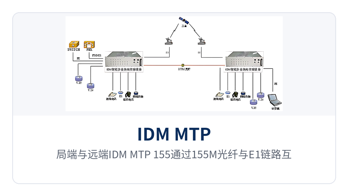
Figure 2: Schematic of the networking topology in which the central office and remote IDM MTP-155 units back each other up through a 155M optical fiber and an E1 link
How to Check Selection and Deployment
Selection starts from the on-site conditions, and the configuration can be determined by checking five items: optical path, E1 capacity, Ethernet interfaces, number of voice channels, and power supply and installation. The five items explain the check contents and common practices one by one, making it easy for the site and commercial teams to confirm in sync and avoid the situation where interfaces are sufficient but optical power or power supply does not match.
- Optical module and distance: select SFP modules according to the optical cable length and attenuation between stations, mainly single-mode with multi-mode optional, with wavelengths at both ends matched as a pair; for links beyond 40Km, long-distance optical modules are optional;
- E1 capacity: count the number of channels occupied by dispatch telephone, telecontrol, and protection signals, plan according to 16 E1 interfaces, and reserve backup channels;
- Ethernet interfaces: allocate according to 4 10/100M interfaces, connecting IP phones, video, and production data to different interfaces to avoid mixed connections of different services;
- Number of voice channels: count the number of 2-wire and 4-wire voice channels; 16 channels of 2-wire and 4 channels of 4-wire are the standard configuration, and any excess is supplemented with boards in the expansion slots;
- Power supply and installation: check whether the site is AC220V, DC-48V, or DC24V and whether dual hot standby power supplies are required; the 19-inch 3U chassis is installed in a standard cabinet.
During deployment, first deploy the central office and remote end as a pair, then confirm how the E1 backup channel is established. Where fast service recovery after a fiber break is required, the E1 link is pre-established and maintained in hot standby mode, with a switchover time of no more than 50ms; for sites without dedicated line conditions, the backup channel can be established by dial-up or integrated network management mode, with switchover times within 15s and 50s respectively.
Conclusion
For field and private network sites, the value of the transmission segment lies in whether one optical fiber can carry telephony, data, and Ethernet all at once. As a 155M field multi-service optical transmission device, IDM MTP-155 uses a 19-inch 3U chassis to bring 16 E1 interfaces, 4 Fast Ethernet interfaces, and 20 voice channels into the same device, so only one model needs to be maintained at the site side. As a professional optical transmission equipment and optical multiplexer manufacturer, Raytrans continues to provide product showcase and solution support for private network users on its SDH and MSTP product lines; the degree of cooperation of an SDH equipment manufacturer at the selection stage directly affects the efficiency of project implementation.
SFP optical ports transmit over 40Km with receiver sensitivity better than -32dBm, and intelligent mutual backup between the optical path and the E1 link switches services to the backup channel when the optical cable fails; the 4 expansion slots are populated as required, so service capacity expansion does not require replacing the entire unit. For upgrade projects, check the E1 capacity, Ethernet interfaces, number of voice channels, and power supply format according to the on-site service list to determine the optical module and board configuration.