IDM MSAP622/155 Aggregation-Type SDH Equipment
Three technologies in one frame save two devices; 6U card-based expansion on demand; optical port rate change and mutual backup online
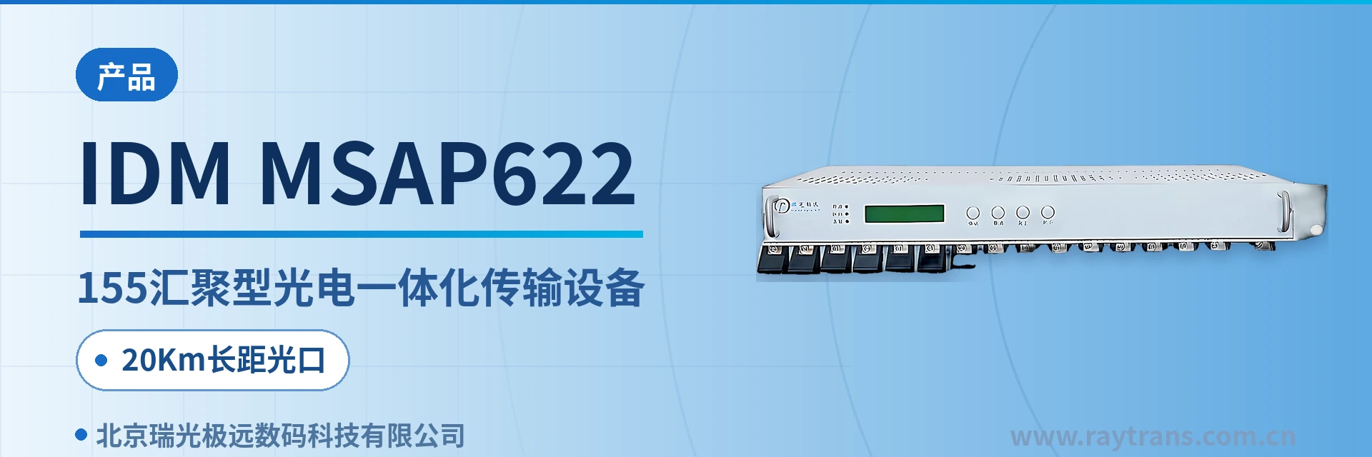
The IDM MSAP622/155 SDH equipment adopts a 19-inch (6+1)U card-based structure. The MSAP equipment can be configured with different numbers and types of tributary service boards according to actual needs, providing multi-service access functions. The MSAP equipment can provide STM-1/STM-4 uplink optical interfaces. The optical access board types of the MSAP equipment include STM-1 access boards and STM-4 aggregation boards; downstream, it provides access for multiple services such as gigabit Ethernet, Fast Ethernet, E1 services, telephone services, and various 64K services.
IDM MSAP622/155 is a 622M aggregation-type optical-electrical integrated transmission device developed by Beijing Ruiguang Jiyuan Digital Technology Co., Ltd. It consists of STM-4 and STM-1 optical transmission units, a cross-connect aggregation unit, and card-based service access units. It is used for service access, transmission, and aggregation at the access layer of data communication networks, and is an SDH equipment designed for access-layer aggregation scenarios.
The unit adopts a 19-inch 6U card-based structure, providing STM-4 uplink optical interfaces and STM-1 access optical interfaces upward, and inserting different types of tributary cards downward according to the service point table, supporting access to gigabit Ethernet, Fast Ethernet, E1, telephone, and various 64K services. The device integrates three technologies—SDH transmission, PBX voice switching, and all-optical Ethernet switching—into a single chassis. As a representative model in the access-layer product showcase of an SDH equipment manufacturer, its card-based structure facilitates on-demand configuration of various service interfaces.
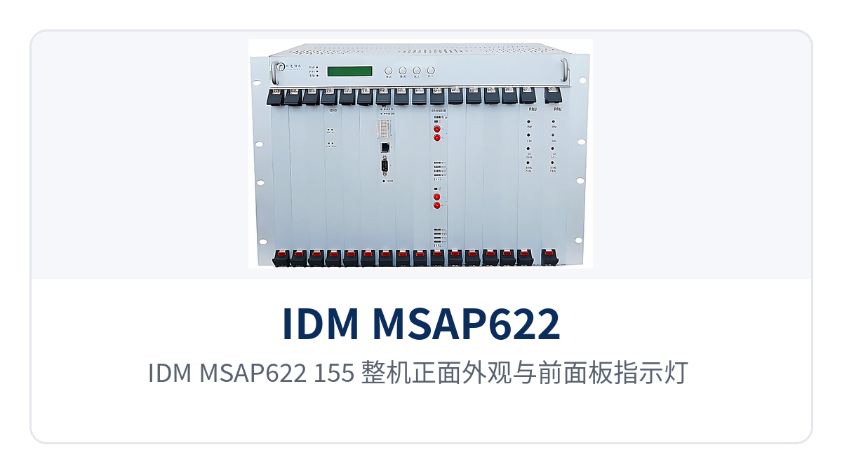
Figure 1: Front view of the IDM MSAP622/155 unit with close-ups of the front panel indicator LEDs and service card slots
Key Specifications at a Glance: STM-4 622M uplink · E1 N×VC12 channelization · Dual power supply -48V/220V · 20Km long-distance optical port · Receive/transmit rates 622.08Mbps and 155.52Mbps · ≤150W overall power consumption · 19-inch 6U card-based
In networking applications, the device can serve as optical transmission equipment to handle transmission and aggregation of access-layer services, supporting MSTP multi-service transport capabilities, and is suitable for access node deployment in government private network optical fiber communication solutions. Meanwhile, its compact 6U card-based structure and dual power supply configuration also suit scenarios with high requirements for space and power supply adaptability, such as military emergency communications vehicle solutions. As an optical multiplexer manufacturer, Raytrans has continued the optical-electrical integrated design approach in this model, providing a flexible product showcase solution for access-layer SDH and MSTP hybrid networking.
How does the 622M aggregation-type optical-electrical integrated transmission device aggregate multiple STM-1 links into a single 622M uplink
The uplink side is tiered by optical access card: the STM-4 aggregation card operates at 622.08Mbps, and the STM-1 access card operates at 155.52Mbps. The two card types are inserted into different slots of the same chassis, and access sites and aggregation sites are configured separately according to network hierarchy. When fully configured, STM-4 optical interfaces can reach 20 and STM-1 optical interfaces can reach 56, with the actual number determined by the card configuration. As a mature product of a professional SDH equipment manufacturer, the device plays a key role in the optical transmission equipment field by aggregating multiple STM-1 services into a 622M uplink.
Cross-connection is the core of aggregation: the STM-4 cross-connect aggregation card provides, per card, non-blocking cross-connection of 32×32 VC-4s, 2016×2016 VC-12s, and 512×512 64K time slots, supporting unidirectional, bidirectional, and broadcast services.
The STM-1 cross-connect aggregation card provides, per card, 441×441 VC-12s and 1024×1024 64K time slots, likewise supporting unidirectional, bidirectional, and broadcast services. VC-12 is the SDH channel granularity that carries 2.048Mbps E1; one VC-4 accommodates 63 VC-12s, and E1, Ethernet, and 64K services each occupy an independent container. This SDH cross-connect architecture enables the device to flexibly schedule various service granularities in MSTP networking.
Reliability is implemented at the module level: the STM-4 cross-connect aggregation card, main control card, and power card are all configured in mutual backup mode. The STM-4 cross-connect aggregation card provides 4 STM-4 optical interfaces, the optical ports can be configured online to STM-1 rate, and any two STM-4 optical ports can back up each other. Maintenance or expansion is performed by card-by-card replacement, while the time slots and cabling of the remaining service cards remain unchanged.
Functional composition: transmission, cross-connection, service access, synchronization, and network management each handle their part
Functions are organized along five lines: transmission, cross-connection, service access, synchronization, and network management. The table below lists each function item and its role. When configuring an MSAP device, verify card types and quantities against the project service point table. The interface quantities in the table are the maximum capacity with fully configured cards; actual configuration is subject to slots and cross-connect capacity.
| Function | Description |
|---|---|
| SDH optical transmission | Provides STM-4 (622.08Mbps) and STM-1 (155.52Mbps) optical interfaces upward; fully configured with 20 STM-4 interfaces and 56 STM-1 interfaces |
| VC-4, VC-12, and 64K cross-connection | STM-4 cross-connect aggregation card: 32×32 VC-4s, 2016×2016 VC-12s, 512×512 64K time slots non-blocking cross-connection per card; STM-1 cross-connect aggregation card: 441×441 VC-12s, 1024×1024 64K time slots |
| E1 access | Fully configured with 536 E1 interfaces, compliant with ITU-T G.703, impedance 75Ω/120Ω, frame structure PCM30/32, channel-associated signaling |
| Ethernet access | Fully configured with 104 FE interfaces, each group bandwidth N×VC12 (N≤50); fully configured with 16 GE interfaces, each group bandwidth N×VC12 (N≤63); both support IEEE802.3 |
| Telephone and audio | Fully configured with 210 FXS/FXO/magneto interfaces and 100 E&M 2/4-wire interfaces; voice encoded at ITU G.711 A-law 64Kbps |
| 64K data | Fully configured with 210 codirectional 64K interfaces and V.24 interfaces (asynchronous ≤9600bps, synchronous 64Kbps); V.35 interfaces n×64Kbps (n=0–31) |
| Digital trunk | Digital trunk card can be inserted, providing 8×N trunk interfaces (N≤8) |
| Signaling gateway | Signaling gateway card can be inserted, supporting SS7, No.1, PRI, V5.2, and other signaling |
| Ethernet aggregation card | G3-EOSEOP card provides 4 groups of independent Ethernet aggregation interfaces; in EOS mode each group supports access from 63 directions; G3-2GE card provides 2 GE groups, each with 1 optical and 1 electrical port, bandwidth N×VC12 (N≤63) |
| Synchronization timing | Clock source selectable among line clock, external clock (2Mbit/s or 2MHz), and free-run |
| Network management and alarms | Provides Ethernet management channels based on DCC, E1, N×64K, and TCP/IP; connects to the Netguard management system; supports the simple network management protocol (SNMP) |
| Networking and NE configuration | The same device can be configured as TM, ADM, or MADM; supports point-to-point, chain, ring network, star, tree, ring-to-ring, and intersecting ring networking |
| Thermal design | Natural cooling and forced fan cooling; intelligent temperature-controlled fans and fan status detection |
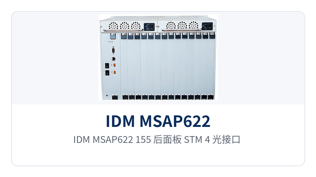
Figure 2: Rear panel layout of the IDM MSAP622/155 showing STM-4 optical interfaces, E1 and Ethernet service interfaces, and power terminals
The above functional composition enables the device to be deployed as standalone SDH equipment or as an MSTP platform carrying multi-service access. In product showcases it is often presented to users in the form of a card configuration table. As an optical multiplexer manufacturer, Raytrans uses this series of devices as aggregation-layer nodes in both government private network optical fiber communication solutions and military emergency communications vehicle solutions, leveraging the cross-connection scheduling capability of SDH equipment to complete unified uplink of multiple E1 and Ethernet services.
How to verify key specifications: optical ports, E1, Ethernet, voice, and power supply
Specifications are listed in groups: optical interfaces, E1, Ethernet and data, voice, and power supply and environment. The verification order is to first calculate the optical power budget and inter-station distance, then count E1 directions and service points, and finally confirm the power supply mode and cabinet space. Values in the table are taken from product technical documentation; engineering calculations are subject to on-site optical fiber and cabling conditions. As an SDH equipment manufacturer, Raytrans lists these interface specifications item by item in its optical transmission equipment product showcase, making it easy for private network users to verify selection.
Optical interfaces and 20Km transmission distance
STM-4 uses SFP optical modules, and STM-1 uses FC optical interfaces; single-mode is the standard configuration, with multimode optional. Transmit optical power is -12 to -6dBm, receiver sensitivity is better than -32dBm, and standard single-mode transmission distance is 20Km. When station spacing exceeds the standard configuration, long-distance optical modules can be installed to extend reach without changing the chassis or service time slot configuration. The optical interfaces of this SDH equipment series are selected according to board rate level and can be directly incorporated into government private network optical fiber communication solutions during MSTP networking.
| Item | Parameter/Specification | Description/Applicable Conditions |
|---|---|---|
| Interface type | STM-4: SFP; STM-1: FC | Pluggable optical modules; single-mode is standard, multimode optional |
| Receive/transmit rate | 622.08Mbps/622.08Mbps (STM-4), 155.52Mbps/155.52Mbps (STM-1) | Receive and transmit rates are identical; selected by board rate level |
| Receive/transmit wavelength | 1310nm/1550nm | Modules at both ends are paired by wavelength |
| Transmit optical power | -12 to -6dBm | Used for optical link budget calculation |
| Receiver sensitivity | Better than -32dBm | Receive threshold for weak optical links |
| Transmission distance | 20Km | Standard single-mode configuration; long-distance optical modules optional for longer reach |
E1 interfaces: 2.048Mbps bit rate and N×VC12 channelization
E1 tributaries comply with ITU-T G.703 recommendations, with a bit rate of 2.048Mbps, HDB3 line code, PCM30/32 frame structure, and 75Ω or 120Ω impedance selected according to on-site cabling. Each E1 is mapped into one VC-12 container, and E1 time slots on the line are assigned by the cross-connect matrix to designated directions. E1 channelization supports N×VC12 (N≤50/63), allowing E1 services to be flexibly converged into 622M or 155M optical channels. The E1 tributaries of SDH equipment can directly interface with existing PDH and PCM equipment, and handle convergence of voice channels and telecontrol services in military emergency communications vehicle solutions.
| Item | Parameter/Specification | Description/Applicable Conditions |
|---|---|---|
| Bit rate | 2.048Mbps | Standard E1 line rate |
| Line code | HDB3 | Consistent with domestic E1 line standards |
| Standard protocol | Supports ITU-T G.703 | Can directly interface with 2M tributaries of SDH, PDH, and PCM equipment |
| Impedance | 75Ω/120Ω | Coaxial or balanced access, selected according to on-site cabling |
| Frame structure | PCM30/32 | 32 time slots per frame, 30 time slots carry services |
| Signaling | Channel-associated signaling | Voice channel status is transmitted together with voice time slots |
| Interface quantity | Fully configured 536 channels | Calculated according to site E1 direction count and protection mode |
Ethernet interfaces: FE N≤50 per group, GE N≤63 per group
Fully configured with 104 FE interfaces and 16 GE interfaces, all RJ-45, supporting IEEE802.3 and full/half duplex adaptive. Ethernet bandwidth is set as N×VC12: FE bandwidth N≤50 per group, GE bandwidth N≤63 per group. Ethernet services and E1 each occupy independent VC-12 containers within the same 622M optical channel and do not preempt each other's bandwidth. MSTP multi-service carrying capability enables Ethernet and E1 to converge in parallel within the same SDH equipment, reducing the variety of equipment in government private network optical fiber communication solutions.
| Item | Parameter/Specification | Description/Applicable Conditions |
|---|---|---|
| FE interface | RJ-45, N×VC12 (N≤50) | IEEE 802.3 compliant, full/half duplex/adaptive, 104 ports at full configuration |
| GE interface | RJ-45, N×VC12 (N≤63) | IEEE 802.3 compliant, full/half duplex/adaptive, 16 ports at full configuration |
| Codirectional 64K interface | G.703 standard, 64Kbps, balanced 120 Ω | Fully compliant with ITU-T G.703 recommendation |
| V.24 interface | Asynchronous ≤9600bps; synchronous 64Kbps | Electrical characteristics comply with CCITT V.28 protocol |
| V.35 interface | RJ-45, n×64Kbps (n=0~31) | Compliant with ITU-T V.35 recommendation; terminal interface complies with ISO2593 |
| Digital trunk interface | 8×N (N≤8) | Provided by the digital trunk card for trunk access on the switch side |
Voice and 64K Data Interfaces
Telephone services are implemented with four types of interface cards: FXO, FXS, magneto, and EM2/4-wire. Voice is uniformly encoded at ITU G.711 A-law 64Kbps and intercommunicates with existing PCM networks, so no transcoding device is required at either end. 64K data services cover three interface types: codirectional 64K, V.24, and V.35. Telecontrol, monitoring, and router uplinks select cards by rate, and all time slots are assigned within the same cross-connect matrix. The optical multiplexer manufacturer calculates card configuration against the site voice channel point table, with voice and data services sharing SDH time slot resources.
| Item | Parameter/Specification | Description/Applicable Conditions |
|---|---|---|
| FXO/FXS audio range | 300Hz~3400Hz | Transmission within the voice frequency band |
| Compression | ITU G.711 A-law | 64Kbps voice encoding, intercommunication with PCM networks |
| Impedance | Three-element complex impedance 200Ω+560Ω//0.1μF | 2-wire telephone interface specification |
| Loop current | 20mA per channel | Telephone power feeding current |
| EM2/4-wire and magneto interface | Audio 300Hz~3400Hz, balanced 600 Ω impedance | Compression ITU G.711 A-law, return loss no less than 18 dB |
| Number of interfaces | FXS/FXO/magneto 210 at full configuration, EM2/4-wire 100 | Cards configured per site voice channel point table; voice channels multiplexed in 64K time slots |
Power Supply, Power Consumption, and Installation Environment
Power supply formats are selectable between AC220V and DC-48V. AC equipment rooms and DC sites share the same model, so only one type of spare part is needed. Overall power consumption is ≤150W, keeping power supply access and heat dissipation manageable at full card configuration. The STM-4 cross-connect aggregation board, main control card, and power card are configured for mutual backup; wiring terminals and polarity are subject to the accompanying technical documentation. This power supply design suits the DC power supply conditions of military emergency communications vehicle solutions and also meets the long-term online requirements of unattended sites in government private network optical fiber communication solutions.
| Item | Parameter/Specification | Description/Applicable Conditions |
|---|---|---|
| Power supply mode | AC220V/DC-48V | Dual power supply formats selectable, chosen per equipment room power supply conditions |
| Overall power consumption | ≤150W | Unit power draw at full card configuration |
| Key module backup | STM-4 cross-connect aggregation board, main control card, power card in mutual backup | Inspection by card-by-card replacement, other services unaffected |
| Operating temperature | -10℃~+50℃ | Communications equipment rooms, substation communication rooms, and field cabinets |
| Relative humidity | 0~95% (non-condensing) | Normal operation under non-condensing conditions |
| Dimensions | 482×309×132 (mm) | Length×Depth×Height, 19-inch rack installation |
Differentiated Value: STM-4 622M Uplink, E1 Channelization, and Dual-Power Low Power Consumption
Each of the three differentiated capabilities has verifiable specifications that can be written directly into technical specifications and bid parameter tables. Uplink rate determines whether an aggregation node can aggregate multiple directions with a single device; channelization capability determines whether service expansion requires hardware replacement; power supply and power consumption determine whether unattended sites can stay online long term. As an SDH equipment manufacturer, Raytrans maps these three capabilities one-to-one to specific parameters in its product showcase, making it easy for private network users to select models according to the actual operating conditions of government private network optical fiber communication solutions and military emergency communications vehicle solutions.
| Differentiation Point | Value for Private Network Users |
|---|---|
| STM-4 aggregation 622Mbps uplink | A single device provides a 622.08Mbps line upward and aggregates multiple STM-1 access links downward, so an aggregation site does not need a separate transmission device for each direction |
| E1 channelization supports N×VC12 (N≤50/63) | E1 services are aggregated at VC-12 granularity; FE bandwidth per group N≤50 and GE bandwidth per group N≤63; expansion only adjusts bandwidth configuration without changing hardware |
| Dual power supply AC220V/DC-48V, overall power consumption ≤150W | The same model works in AC equipment rooms and -48V DC sites; full-configuration power draw ≤150W, keeping backup power and heat dissipation pressure at unattended sites manageable |
| 20Km long-distance optical port | Adjacent sites within 20Km can be directly connected, eliminating repeater equipment rooms; for greater station spacing, long-distance optical modules can be swapped in without changing the chassis |
Typical Application Scenarios
The 622M aggregation-type optical-electrical integrated transmission equipment targets the private network access layer and aggregation layer. Electric power private networks, rail transit communication, and military and government private networks are three typical deployment positions. The service point tables of the three site types differ, but the card configuration approach is the same: first determine voice channels and E1 directions, then Ethernet ports, and finally select the power supply format according to on-site power conditions. As the main product of an SDH equipment manufacturer at the access layer, this series is often presented in the product showcase with multi-service plug-in board capability as its core selling point.
Electric Power Private Network: Multi-Service Same-Fiber Backhaul Between Substations and Dispatch Centers
Services from substations and switching stations to dispatch centers are mainly dispatch telephone, telecontrol data, monitoring, and office network. Single-site service volume is small but varied. The MSAP622/155 accesses services by card within the station: dispatch telephone via FXO/FXS cards, telecontrol and protection channels via E1 cards, and monitoring and office via FE/GE cards, with a single optical fiber backhauling voice and data simultaneously. This design based on a hybrid SDH and MSTP architecture enables the optical transmission equipment to handle both TDM services and packet services on a single platform.
Substations are mostly unattended, and power can be drawn directly from the station's -48V DC distribution panel; overall power consumption ≤150W places less discharge pressure on storage batteries. Inspection is performed card by card, and the mutual backup structure of the cross-connect aggregation board, main control card, and power card allows single-card replacement without stopping station-wide services; adding a new bay only requires adding service cards and time slot configuration.
Rail Transit Communication: Voice and Data Aggregation for Stations Along the Line and Section Stations
Stations along rail lines and section stations have long spacing and short maintenance windows. Communication services include official telephone, section telephone, PA audio, and monitoring data. On the station side, the device accesses various services via E1, FE/GE, and telephone cards and sends them to the center over a 622M uplink. When station spacing is within 20Km, direct connection is possible without adding repeater equipment in the section. For SDH equipment manufacturers undertaking such projects, the 622M aggregation-type platform provided by Raytrans can reduce the number of repeater nodes in direct-connection section scenarios.
Stations along the line can form a ring network by closing in two directions, or be connected in sequence as a chain network. Ring network protection is completed at the transmission layer; during section optical cable cutover, services are delivered along the other direction, and the dispatch center does not need to reconfigure site by site. Station cabinets are consolidated in a single 6U chassis, and the number of patch cords and wiring decreases along with the number of devices.
Military and Government Private Networks: 6U Chassis Configured by Mission for Rapid Deployment
Power supply conditions at field command posts and temporary duty posts vary with the site, with mains power, generators, and DC distribution panels coexisting. The AC220V and DC-48V dual power supply formats let the same device be installed in cabinets with different power supply conditions, so no temporary power conversion device is needed when moving into different sites. This feature is particularly practical in military emergency communications vehicle solutions and government private network optical fiber communication solutions, where no additional power conversion unit is required during emergency deployment.
The 6U card-based structure supports mission-based card configuration: first insert telephone cards and E1 cards to open basic command voice channels, then add Ethernet boards, digital trunk cards, and signaling gateway cards as needed. The unit supports point-to-point, chain, ring, star, and tree networking topologies, and the same device can be configured as TM, ADM, or MADM. During mobile deployment, hoisting and wiring effort decreases along with the number of devices.
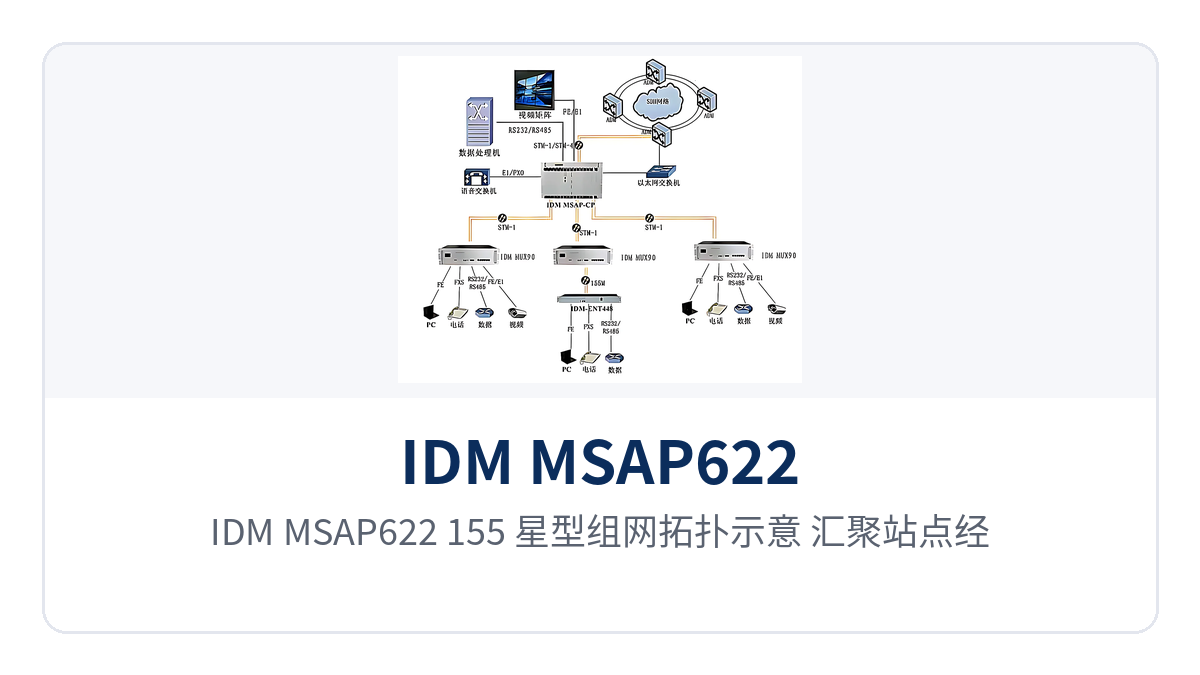
Figure 3: IDM MSAP622/155 star networking topology schematic, with the aggregation site connected to multiple access sites via a 622M uplink
Conclusion
As a 622M aggregation-type optical-electrical integrated transmission device, the IDM MSAP622/155 uses an STM-4 uplink to address aggregation node bandwidth, E1, FE/GE, telephone, and 64K plug-in boards to address service variety, and dual power supply with ≤150W power consumption to address site power supply access. In access layer projects of electric power, rail transit, and military and government private networks, a single 6U chassis simultaneously handles access, cross-connection, and transmission, reducing rack space, the number of patch cords, and the variety of spare parts. For optical multiplexer manufacturers and system integrators, this platform can serve as an integrated access and aggregation node in government private network optical fiber communication solutions and military emergency communications vehicle solutions.
Unified models also simplify cross-line transfers and spare parts sharing: STM-1 access boards and STM-4 aggregation boards are mixed by site level, expansion only requires adding service cards, while the chassis and external wiring remain in use, and the time slots and wiring of existing services need not be rearranged.