IDM MSAP155-24 SDH Multi-Service Access Platform
6-slot mixed insertion, 24-channel E1, dual optical ports 40 km, one unit replaces an optical multiplexer plus PCM
IDM MSAP155-24 SDH equipment: 155M optical interface, 19-inch 2U standard chassis, single-board device, standard 2U chassis. The MSAP device provides 2 pluggable power supply units, STM-1 dual optical ports, dual-fiber single-mode FC interfaces, 40 km optical transmission, and 6 service slots. The MSAP device provides up to 24 E1 access channels.
The IDM MSAP155-24 SDH multi-service access platform is an SDH device developed by Beijing Ruiguang Jiyuan Digital Technology Co., Ltd. (Raytrans). It adopts a 6-slot, 24-channel E1 access design and consists of an STM-1 optical transmission unit, a PCM multiplexing unit, and pluggable service interface cards. It is used to aggregate telephone, E1, Ethernet, and low-speed data services into a single 19-inch 2U chassis, and is a typical optical transmission equipment product showcase for private network access scenarios.
At private network access sites, rack positions, fiber cores, and power supply conditions are often constrained at the same time, yet the site still needs to upload dispatch telephone, telecontrol data, and office network services simultaneously. This SDH device is deployed in a standard 2U chassis, with 6 service slots populated with cards according to the site service list. The site side no longer needs to cascade standalone optical multiplexers and PCM multiplexers, reducing both rack space occupancy and points of failure. As a professional SDH equipment manufacturer, Raytrans integrates SDH and MSTP capabilities in this platform, flexibly carrying the multi-service access requirements in government private network optical fiber communication solutions and military emergency communications vehicle solutions.
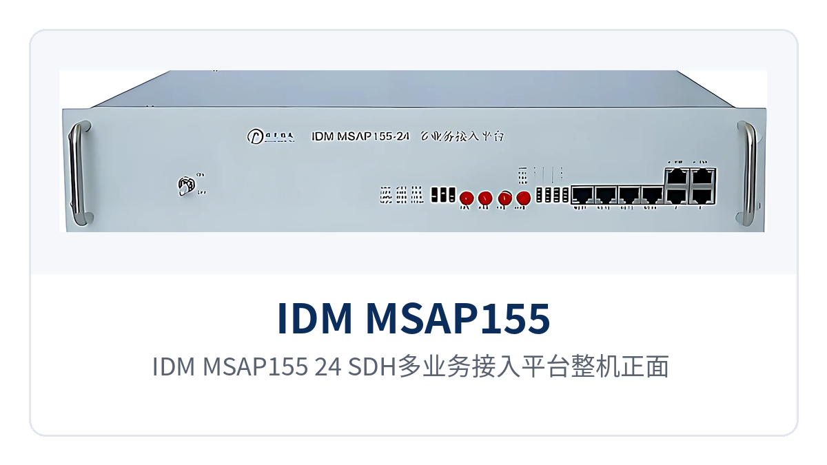
Figure 1: Front view of the IDM MSAP155-24 SDH multi-service access platform, 19-inch 2U chassis with dual power supply unit panel
Key specifications at a glance: Dual STM-1 optical ports · 40 km single-mode transmission · 6 service slots · 24-channel E1 access · Dual pluggable power supplies · AC 220 V/DC -48 V dual power supply · 19-inch 2U chassis · -30 °C to +50 °C wide temperature
What kind of device is the 6-slot 24-channel E1 access platform
The 6-slot 24-channel E1 access platform refers to an SDH device that organizes interfaces on the tributary side with 6 service slots and provides a maximum E1 access capacity of 24 channels. It is an access layer product in the optical transmission network and a typical product showcase form of SDH equipment manufacturers for access scenarios. For service capacity expansion, simply add or replace cards while the chassis and optical paths remain in use, so the investment goes into the cards rather than the complete unit.
The service mix is determined by the cards: the same model of SDH device can provide telephone and E1 access at a substation or data aggregation along a rail line, with the difference reflected only in the card configuration. The unit uses a 19-inch 2U standard chassis with dimensions of 440×230×90 mm and can be installed in a standard cabinet and communications rack.
What can each of the 6 service slots accommodate
The 6 slots are configured in combination according to the site service list, with interface types covering voice, E1, Ethernet, and low-speed data, and the cards do not affect each other. The capacity per card and the available card types are not yet recorded in the knowledge base; confirm with the manufacturer against the service list during configuration and reserve margin for future capacity expansion.
- E1 interface: carries 2.048 Mbps E1 services, complies with ITU-T G.703, with 75 Ω/120 Ω impedance selected according to on-site cabling.
- Telephone interface: connects dispatch telephones and administrative telephones, with a voice frequency band of 300 Hz to 3400 Hz, ITU G.711 A-law encoding, and a loop current of 25 mA per channel.
- Ethernet interface: provides an RJ-45 interface, complies with IEEE 802.3, supports full/half duplex adaptive, with a per-channel bandwidth of N×2.048 Mbps (N≤63).
- Audio interface: balanced 600 Ω, return loss no less than 18 dB, used for 2-wire/4-wire audio and broadcast services.
- 64K data interface: complies with G.703, bit rate 64 Kbps, balanced 120 Ω.
- Low-speed data interface: V.24 channel asynchronous ≤9600 bps, synchronous 64 Kbps, complies with CCITT V.28; V.35 channel n×64 Kbps (n=0~31), complies with ITU-T V.35 recommendation.
How the 2U chassis and dual pluggable power supplies ensure reliability
The device provides 2 groups of pluggable power supply units, with power supply modes supporting AC 220 V and DC -48 V. Sites with a DC distribution panel can use -48 V directly, while sites with only mains power use AC; both modes are selectable on the same model. Power supply units are replaced by plugging or unplugging, so maintenance does not require removing the complete unit and returning it to the factory.
The overall power consumption is ≤50 W, with an operating temperature of -30 °C to +50 °C and a relative humidity of 0 to 95% (non-condensing), covering the operating conditions of substation relay protection rooms, equipment compartments along rail lines, and field cabinets. The dual power supply units and wide-temperature design together determine the service availability duration of unattended sites.
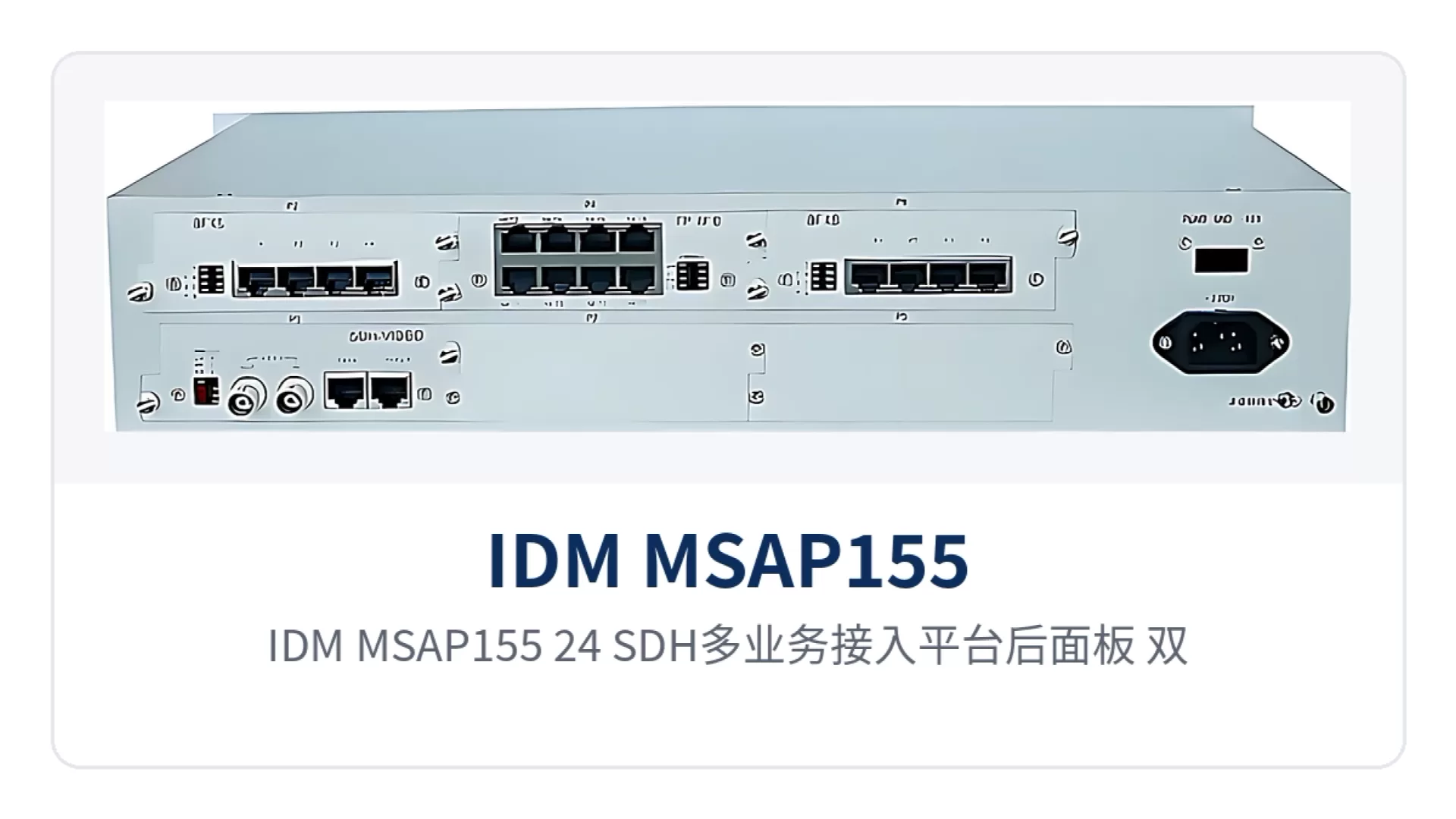
Figure 2: Rear panel of the IDM MSAP155-24 SDH multi-service access platform, layout of dual STM-1 optical interfaces, service cards, and pluggable power supply units
Core functions
The platform integrates SDH optical transmission, PCM multiplexing, and multi-service access in a single chassis, with functions covering four categories: transmission, multiplexing, access, and power supply, listed item by item in the table below. The interface specifications in the table are listed according to the capabilities of the complete unit; during configuration, cards are added according to the site service list.
| Function | Description |
|---|---|
| SDH optical transmission | Provides 2 STM-1 optical interfaces, receive/transmit rate 155 Mbps, interface type FC (SC and others can be customized), mainly single-mode with optional multi-mode |
| PCM multiplexing | Multiplexes voice channels and data according to the PCM30/31 frame structure, with channel-associated signaling, interoperable with existing PCM networks |
| 6 service slots | 6 slots are mixed with service interface cards according to the site service list; capacity expansion only involves the cards, while the chassis and backplane remain in use |
| 24-channel E1 access | Maximum E1 access capacity of the complete unit is 24 channels, bit rate 2.048 Mbps, line code HDB3, 75 Ω/120 Ω impedance selectable |
| Telephone access | Voice frequency band 300 Hz to 3400 Hz, compression ITU G.711 A-law, loop current 25 mA per channel |
| Ethernet access | RJ-45 interface, transmission rate N×2.048 Mbps (N≤63), complies with IEEE 802.3, full/half duplex/adaptive |
| Audio access | Balanced 600 Ω audio interface, return loss no less than 18 dB, carries dispatch and broadcast audio services |
| 64K data access | Line code complies with the G.703 standard, bit rate 64 Kbps, balanced 120 Ω impedance |
| V.24 low-speed data | Asynchronous ≤9600 bps, synchronous 64 Kbps, electrical characteristics comply with the CCITT V.28 protocol |
| V.35 data | RJ-45 interface, transmission rate n×64 Kbps (n=0~31), complies with ITU-T V.35 recommendation, terminal interface complies with ISO 2593 |
| Dual pluggable power supplies | 2 groups of power supply units, supporting AC 220 V and DC -48 V; power supply maintenance is performed by plugging or unplugging |
| Wide temperature operation | Operating temperature -30 °C to +50 °C, relative humidity 0 to 95% (non-condensing), suitable for unattended sites |
Key technical specifications
The specifications in the table below are taken from the product technical documentation and are suitable for verification during networking design and equipment selection. Items not listed are subject to the accompanying technical documentation and commercial confirmation. The recommended verification order is to first check the optical interfaces and transmission distance, then the E1 and service interfaces, and finally confirm the power supply and environmental conditions.
Optical interfaces and transmission distance
| Item | Parameter/Specification | Description/Applicable Conditions |
|---|---|---|
| Interface type | FC (SC and others can be customized) | Optical port type selected according to on-site optical distribution |
| Fiber mode | Single-mode (multi-mode optional) | Single-mode for inter-station links, multi-mode for short-distance patching within an equipment room |
| Receive/transmit rate | 155 Mbps/155 Mbps | Corresponds to the STM-1 line rate |
| Receive/transmit wavelength | 1310 nm/1550 nm | Determined by the equipped optical module |
| Transmit optical power | -12 to -6 dBm | Transmitter-side specification for the optical power budget |
| Receiver sensitivity | Better than -32 dBm | Receiver threshold for link attenuation calculation |
| Transmission distance | 20 km standard, up to 40 km and above with long-distance optical modules | Inter-station distance stated at ordering; optical modules supplied by the manufacturer |
E1 channel
| Item | Parameter/Specification | Description/Applicable Conditions |
|---|---|---|
| Number of channels | 24 | Maximum E1 access capacity of the complete unit, implemented according to card configuration |
| Bit rate | 2.048 Mbps | Complies with ITU-T G.703 recommendation |
| Line code | HDB3 | Consistent with domestic E1 line formats |
| Impedance | 75 Ω/120 Ω | Coaxial and balanced access modes selected according to on-site conditions |
| Frame structure | PCM30/31 | Channel-associated signaling |
Service interfaces
| Item | Parameter/Specification | Description/Applicable Conditions |
|---|---|---|
| Ethernet interface | RJ-45, N×2.048 Mbps (N≤63) | Complies with IEEE 802.3, full/half duplex/adaptive |
| Telephone audio range | 300 Hz to 3400 Hz | Compression ITU G.711 A-law |
| Telephone interface impedance | Three-element complex impedance 200 Ω+560 Ω//0.1 μF | 2-wire telephone interface specification, loop current 25 mA per channel |
| Audio interface | Balanced 600 Ω, return loss no less than 18 dB | 2-wire/4-wire audio and broadcast services |
| 64K interface | G.703 standard, 64 Kbps, balanced 120 Ω | Fully complies with ITU G.703 recommendation |
| V.24 interface | Asynchronous ≤9600 bps, synchronous 64 Kbps | Electrical characteristics comply with the CCITT V.28 protocol |
| V.35 interface | RJ-45, n×64 Kbps (n=0~31) | Complies with ITU-T V.35 recommendation, terminal interface complies with ISO 2593 |
Complete unit and power supply
| Item | Parameter/Specification | Description/Applicable Conditions |
|---|---|---|
| Chassis structure | 19-inch 2U standard chassis | Dimensions 440×230×90 mm, can be installed in a standard cabinet |
| Service slots | 6 | Interface cards configured according to the site service list |
| Power supply mode | AC 220 V/DC -48 V | 2 groups of pluggable power supply units, both modes selectable |
| Overall power consumption | ≤50 W | Estimated with fully populated cards, used for equipment room power distribution and storage battery calculation |
| Operating temperature | -30 °C to +50 °C | Covers outdoor cabinet and equipment compartment environments |
| Relative humidity | 0 to 95% (non-condensing) | Operates in non-condensing environments |
How to network with dual STM-1 optical ports and 40 km single-mode transmission
Dual STM-1 optical ports means the complete unit provides 2 STM-1 optical interfaces at 155 Mbps, with a receive/transmit rate of 155 Mbps/155 Mbps, receive/transmit wavelengths of 1310 nm/1550 nm, FC interface type (SC and others can be customized), and fiber mode mainly single-mode with optional multi-mode. As an SDH equipment access layer product, this configuration directly determines the core optical interface capability specifications in the product showcase.
The 40 km single-mode transmission is determined by the equipped optical module: the standard configuration provides a transmission distance of 20 km, with transmit optical power of -12 to -6 dBm and receiver sensitivity better than -32 dBm. When the inter-station distance exceeds this, long-distance optical modules can be installed to extend the single-mode link to 40 km and above, while the interface type and service configuration remain unchanged. For optical transmission equipment scenarios requiring long-distance extension, installing long-distance modules meets the requirement.
The optical power budget determines whether an STM-1 link can be provisioned: the difference between the transmit optical power and the receiver sensitivity constitutes the available attenuation, with patch cords, fiber adapters, and splice points each consuming a portion. Calculated with -12 to -6 dBm transmit power and better than -32 dBm reception, the margin reserved by the standard single-mode configuration is sufficient to cover the connector loss of a 20 km link; for longer links, reserve margin based on measured optical power and replace with long-distance modules.
Two STM-1 optical ports can connect to optical fibers in different directions, and sites are organized into point-to-point, chain, or ring networks according to their distribution: intermediate sites add and drop services locally, and when a section of optical cable on the ring is interrupted, services are rerouted in the other direction. In engineering practice, the topology is first determined based on optical cable resources, and then the optical port wiring and optical module model for each section are determined. Raytrans retains the flexible networking capability of dual optical ports on this series of SDH equipment, making it easy for access layer sites to organize networks according to the actual optical cable routes.
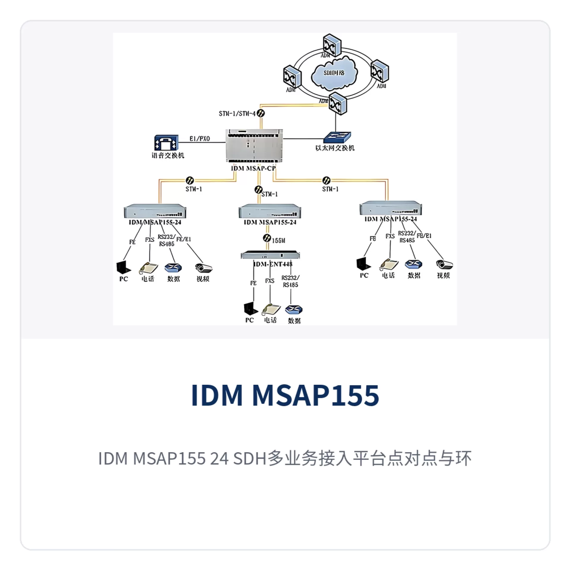
Figure 3: IDM MSAP155-24 SDH multi-service access platform point-to-point and ring networking topology schematic, with remote site services aggregated through STM-1 optical ports
Differentiated Value
When selecting access layer SDH equipment for a private network, the judgment usually comes down to three points: how far the link can reach, how many types of services the enclosure can carry, and how to respond when power supply conditions change. The table below lists the platform capabilities and corresponding value according to these three points, making it easy to compare them item by item with project requirements.
| Differentiated Capability | Value for Private Network Users |
|---|---|
| Dual-port STM-1 | The two 155Mbps optical ports connect to different transmission directions respectively, so chain and ring topologies can be organized on one device, and intermediate sites do not need an additional optical branch device |
| 40km single-mode transmission | Standard 20Km, with optional long-distance modules reaching 40km and above; when the spacing between stations exceeds the standard distance, no repeater equipment room needs to be added, and the backbone section is extended in one go |
| Dual pluggable power supplies | The two power supply units support AC220V and DC-48V, so sites with a DC distribution panel or with mains power only can connect directly, and power supply inspection and replacement are performed by plugging or unplugging |
| 24-channel E1 access | The unit's 24 E1 channels work with 6 service slots, so telephone, data, and Ethernet services are aggregated on the same device, and the number of devices and power distribution circuits at the site side is reduced accordingly |
Typical Application Scenarios
The 6-slot 24-channel E1 access platform sits at the access layer in a private network, aggregating upward through STM-1 optical ports into the transmission system and connecting downward to remote optical multiplexers, switches, and various service terminals. Electric power and energy, rail transit, and military and government private networks are three types of sites with stricter requirements on rack position, wide temperature, and power supply format. Their deployment methods are described one by one below.
Electric Power and Energy Private Network: Simultaneous Voice and Telecontrol Transmission at Substations and Power Supply Business Outlets
Substations and remote power supply outlets have limited rack positions, and within a station there are dispatch telephones, E1 telecontrol channels, and monitoring networks that need to be uploaded at the same time, while fiber core resources are limited. The device is installed in a 2U enclosure in the communication cabinet, and the 6 slots are configured with interfaces according to the service list of the station; telephone and E1 services are aggregated through STM-1 optical ports into the transmission system of the centralized control station.
The -30℃~+50℃ operating range and ≤50W overall power consumption suit the operating conditions of unattended sites. The dual pluggable power supply units allow AC and DC power supply formats to coexist on the same model, so when the station has only a DC distribution panel, no additional conversion equipment is needed.
Rail Transit: Service Aggregation at Stations Along the Line and Section Equipment Rooms
Sites along a rail transit line are distributed and widely spaced, and both the space in the communication equipment compartment and the inspection window are limited. The device uses a 19-inch 2U enclosure and a card-based structure, and service interfaces are configured according to the actual voice channel and data requirements of the site; when adding services, it is sufficient to replace the plug-in board without replacing the entire unit.
The audio interfaces for inter-station telephone and section broadcast are terminated in the same device, and the return loss of the balanced 600 Ω audio interface is no less than 18 dB. Section monitoring data travels over V.24 channels and shares the same optical channel with voice, so the number of devices in the equipment compartment is reduced accordingly.
Military and Government Private Network: SDH Access Nodes at Field Sites
Field sites have complex power supply conditions, with mains power, diesel generators, and solar DC coexisting, and the sites are often unattended for long periods. AC220V/DC-48V dual power supply and the -30℃~+50℃ operating range allow the same model to be installed in cabinets with different power supply formats, so only one type of spare part needs to be kept. In the military emergency communications vehicle solution, this wide-temperature dual-power-supply feature is equally applicable, and switching the power supply format in a vehicle-mounted environment does not affect service provisioning.
40km single-mode transmission, together with receiver sensitivity better than -32dBm, usually makes a repeater unnecessary between adjacent sites. When the link is longer, long-distance optical modules can be installed instead, while the interface type and service configuration remain unchanged; activated voice channels and telecontrol channels are not affected by the upgrade, and the site does not need an additional repeater equipment room. For the government private network optical fiber communication solution, adopting SDH equipment at access layer sites in combination with MSTP networking can ensure reliability while meeting multi-service aggregation requirements.
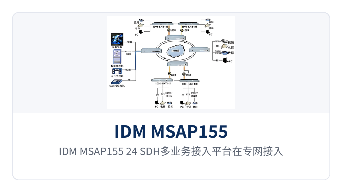
Figure 4: Deployment schematic of the IDM MSAP155-24 SDH multi-service access platform at the private network access layer, with the 2U enclosure and service terminal wiring in the cabinet
Conclusion
As a 6-slot 24-channel E1 access platform, the IDM MSAP155-24 packs STM-1 optical transmission, PCM multiplexing, and multi-service interfaces into a 19-inch 2U enclosure; dual-port STM-1 and 40km single-mode transmission address backbone extension, while 6 service slots and 24-channel E1 access address multi-service aggregation. As an SDH equipment manufacturer, Raytrans balances the respective advantages of MSTP multi-service carrying and SDH rigid pipes on this platform, making it suitable for private network scenarios where multiple services coexist at the access layer.
At access layer nodes of electric power and energy, rail transit, and military and government private networks, there are many types of services but limited rack positions and fiber cores; one optical transmission device undertakes both access and multiplexing, and the number of devices, power distribution circuits, and variety of spare parts at the site side is reduced accordingly. For the specific plug-in board configuration, optical module model, and power supply format, it is recommended to determine them after checking against the project service list and confirming with the manufacturer.