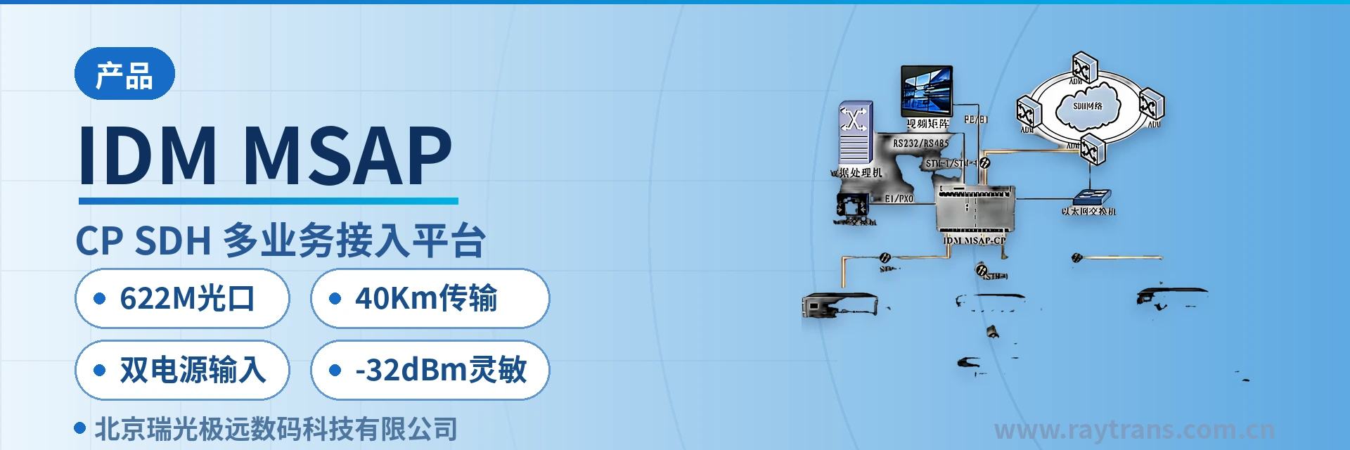
IDM MSAP-G3CP SDH Multi-Service Access Platform
One chassis handles all services, E1 75 Ω/120 Ω optional, dual optical ports 40 km
The IDM MSAP-G3CP SDH multi-service access platform is an STM-1/STM-4/STM-16 level SDH centralized optical transmission system designed with SDH technology. Its technical specifications comply with ITU-T and Chinese SDH standards. The IDM MSAP-G3CP telephone switching system has multiple STM-1/STM-4/STM-16 rate optical interfaces.
The IDM MSAP-G3CP 622M optical port SDH multi-service access platform is a centralized SDH optical transmission system developed by SDH equipment manufacturer Beijing Ruiguang Jiyuan Digital Technology Co., Ltd. (Raytrans). It is used for voice, data, and Ethernet service access, multiplexing, and aggregation at the private network access layer, and is a representative model in the optical transmission equipment product showcase.
The external channels are a 622.08Mbps STM-4 optical port and a 155.52Mbps STM-1 optical port, both supporting 40Km single-mode transmission, with optional long-distance optical modules to extend the distance. The system is planned at STM-1/STM-4/STM-16 levels; the parameters on this page are given for the STM-4 and STM-1 optical interface specifications, applicable to scenarios such as government private network optical fiber communication solutions and military emergency communications vehicle solutions.
Key Specifications at a Glance: STM-4 622.08Mbps · STM-1 155.52Mbps · 622M optical port · 40Km transmission · -32dBm sensitivity · dual power supply input · E1 75Ω/120Ω optional
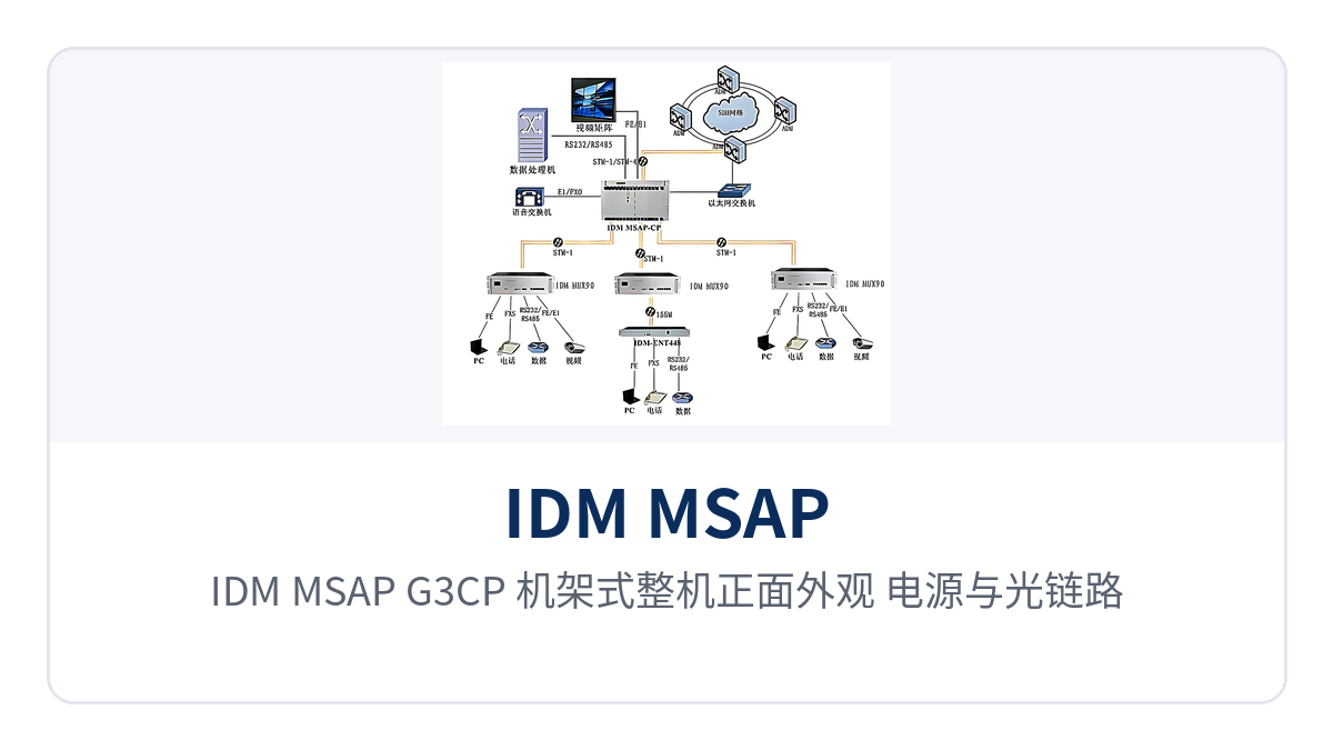
Figure 1: IDM MSAP-G3CP rack-mounted unit front view, power and optical link indicator LEDs, service card area layout
What This Device Is: A Centralized SDH Multi-Service Access Platform
As a centralized SDH device under Raytrans, the IDM MSAP-G3CP uses a 19-inch rack-mounted enclosure with dimensions of 482×309×132mm. Service interfaces are centrally inserted into the same chassis in the form of service cards, forming a complete product showcase solution. The chassis depth of 309mm allows direct installation in a standard 19-inch rack, side by side with existing optical transmission equipment in the same cabinet.
Downstream services include E1 trunk, FE and GE Ethernet, FXO/FXS analog voice channels, E&M 2/4-wire and magneto interfaces, codirectional 64K, and V.24/V.35 low-speed data. After multiplexing within the chassis, multiple service types enter the optical path and are sent upstream via STM-4 or STM-1 optical interfaces, so the equipment room side does not need a separate SDH device for each service type.
Multiple optical interfaces allow the same SDH device to serve as an access or aggregation node in chain, ring, and star networking, making it a commonly used access layer device in MSTP networking. Sites along the line access via STM-1 optical ports while the central station aggregates via STM-4 optical ports—a common configuration path in government private network optical fiber communication solutions, equally applicable to rapid deployment scenarios in military emergency communications vehicle solutions.
What This Device Can Do: Features
The functions of the IDM MSAP-G3CP are organized into four categories: optical transmission, E1 multiplexing, Ethernet access, and voice and data access, each carried by the corresponding service card. The table below lists each function and its purpose for easy cross-checking against the site service list.
| Function | Description |
|---|---|
| STM-4/STM-1 optical transmission | Provides 622.08Mbps STM-4 optical ports and 155.52Mbps STM-1 optical ports, single-mode 40Km, with optional long-distance optical modules to extend the distance |
| E1 trunk access | Provides 2.048Mbps E1 interfaces with HDB3 line coding, compliant with ITU-T G.703, impedance 75Ω/120Ω optional |
| PCM multiplexing | Organizes voice channels per the PCM30/32 frame structure; channel-associated signaling is carried with the voice time slots and can interoperate with existing PCM switching equipment |
| Ethernet access | FE port bandwidth N×VC12 (N≤50), GE port bandwidth N×VC12 (N≤63), compliant with IEEE802.3, full/half duplex/adaptive |
| Analog voice channel access | FXO/FXS interfaces with an audio range of 300Hz~3400Hz, ITU G.711 A-law compression, loop current 20mA per channel |
| Audio and magneto interfaces | E&M 2/4-wire and magneto interfaces with balanced 600Ω impedance, return loss no less than 18 dB |
| Low-speed data access | Codirectional 64K (G.703, 64Kbps, balanced 120Ω), V.24 (asynchronous ≤9600bps, synchronous 64Kbps), V.35 (n×64Kbps) |
| Centralized rack mounting | 19-inch rack-mounted enclosure, AC220V and DC-48V dual power supply input, overall power consumption ≤150W |
Core Parameters and Interface Specifications of the 622M Optical Port SDH Multi-Service Access Platform
Parameters are listed in five groups: optical interfaces, E1 interfaces, Ethernet interfaces, voice and data interfaces, and power and environment. Values are taken from Raytrans product documentation for this SDH equipment model. On-site configuration is subject to the order contract and accompanying technical documentation; optical modules are selected according to actual link distance.
Optical Interface Parameters
The optical port specifications for the two rates, STM-4 and STM-1, are listed separately for easy selection based on site capacity and link distance. Both optical ports share the same set of transmit optical power and receiver sensitivity values; the interface form factors are SFP and FC respectively, and multi-mode modules are also available as an option for short-distance connections within the equipment room.
| Item | STM-4 Optical Interface | STM-1 Optical Interface |
|---|---|---|
| Interface type | SFP | FC |
| Fiber mode | Single-mode (multi-mode optional) | Single-mode (multi-mode optional) |
| Receive/transmit rate | 622.08Mbps/622.08Mbps | 155.52Mbps/155.52Mbps |
| Receive/transmit wavelength | 1310nm/1550nm | 1310nm/1550nm |
| Transmit optical power | -12~-6dBm | -12~-6dBm |
| Receiver sensitivity | Better than -32dBm | Better than -32dBm |
| Transmission distance | 40Km, extendable with optional long-distance optical modules | 40Km, extendable with optional long-distance optical modules |
E1 Interface Parameters
The impedance and signaling mode of the E1 interface determine whether it can directly interoperate with existing PCM equipment at the site. Before ordering, confirm whether the on-site cabling is coaxial or balanced cable, then verify the configuration parameters of the peer switch against the PCM30/32 frame structure and E1 channel-associated signaling.
| Item | Parameter/Specification | Description/Applicable Conditions |
|---|---|---|
| Bit rate | 2.048Mbps | Standard E1 line rate |
| Line coding | HDB3 | Line coding specified in ITU-T G.703 |
| Standard protocol | Supports ITU-T G.703 | International recommendation followed by the E1 interface |
| Impedance | 75Ω/120Ω | 75Ω for coaxial cable and BNC connectors, 120Ω for balanced cable |
| Frame structure | PCM30/32 | 32 time slots per frame, TS0 for frame alignment and alarms, TS16 for channel-associated signaling |
| Signaling | Channel-associated signaling | Voice channel status is carried with the voice time slots, with no separate signaling channel required |
Ethernet Interface Parameters
Ethernet bandwidth is configured in units of VC12, with upper limits of 50 and 63 VC12 for FE and GE interfaces respectively. The service side calculates bandwidth based on the actual traffic of surveillance video, office data, and dispatch data, then converts it into the number of VC12 for the configuration sheet.
| Item | Parameter/Specification | Description/Applicable Conditions |
|---|---|---|
| Interface type | RJ-45 | Ethernet electrical interface |
| FE transmission rate | N×VC12 (N≤50) | Compliant with IEEE802.3, full/half duplex/adaptive |
| GE transmission rate | N×VC12 (N≤63) | Compliant with IEEE802.3, full/half duplex/adaptive |
Voice and Data Interface Parameters
Voice interfaces use ITU G.711 A-law compression with a uniform audio range of 300Hz~3400Hz, and the encoding method is consistent with PCM digital voice channels. Data interfaces are listed by rate and protocol; codirectional 64K, V.24, and V.35 correspond to different terminal devices and transmission rates.
| Item | Parameter/Specification | Description/Applicable Conditions |
|---|---|---|
| FXO, FXS interfaces | Audio range 300Hz~3400Hz, compression ITU G.711 A-law | Three-element complex impedance 200Ω+560Ω//0.1μF, loop current 20mA per channel |
| E&M 2/4-wire interface | Audio range 300Hz~3400Hz, balanced 600Ω impedance | Compression ITU G.711 A-law, return loss no less than 18 dB |
| Magneto interface | Audio range 300Hz~3400Hz, balanced 600Ω impedance | Compression ITU G.711 A-law, return loss no less than 18 dB |
| Codirectional 64K interface | Line coding G.703 standard, bit rate 64Kbps | Balanced 120Ω impedance, fully compliant with the ITU G.703 recommendation |
| V.24 interface | Asynchronous ≤9600bps; synchronous 64Kbps | Electrical characteristics compliant with CCITT V.28 protocol |
| V.35 interface | Interface type RJ-45, transmission rate n×64Kbps (n=0~31) | Compliant with ITU-T V.35 recommendation, terminal interface compliant with ISO2593 |
Power, Environmental, and Mechanical Parameters
Power supply is offered in both AC and DC formats, and environmental specifications cover both communications equipment rooms and unattended sites. Enclosure dimensions determine the rack mounting method, while power consumption and operating temperature determine the power supply and heat dissipation configuration on the equipment room side; all four are calculated together during selection.
| Item | Parameter/Specification | Description/Applicable Conditions |
|---|---|---|
| Power supply mode | AC220V/DC-48V | AC equipment rooms draw from mains power, DC sites draw from -48V basic power supply |
| Overall power consumption | ≤150W | Upper limit of overall power consumption |
| Operating temperature | -10℃~+50℃ | Communications equipment room and industrial site environments |
| Relative humidity | 0~95% (non-condensing) | Normal operation under non-condensing conditions |
| Dimensions | 482×309×132(mm) | Length × depth × height, 19-inch rack installation |
How to Calculate the Optical Power Budget for the 622M Optical Port and 40Km Single-Mode Transmission
The optical power budget equals the difference between the transmit optical power and the receiver sensitivity, and it determines how much fiber and connector loss a link can tolerate. The IDM MSAP-G3CP has a transmit optical power of -12~-6dBm and a receiver sensitivity better than -32dBm; calculated at -6dBm transmit and -32dBm receive, the link budget is approximately 26dB.
G.652 single-mode fiber has an attenuation of about 0.35dB/km at the 1310nm window, so 40Km of fiber itself consumes about 14dB, leaving about 12dB for splice points, mating connectors, and aging margin. This margin level keeps a 40Km link above the sensitivity threshold even in weak-light environments, making link operation more reliable.
When site distance exceeds 40Km, replacing with long-distance optical modules extends the reach without changing the chassis, service cards, or interface configuration. STM-4 optical ports suit the aggregation direction, while STM-1 optical ports suit the access direction along the line; the two rates can be mixed within the same chassis. As an SDH equipment manufacturer, Raytrans configures the optical port rates and budget margins of SDH equipment in its optical transmission equipment product showcase according to this approach.
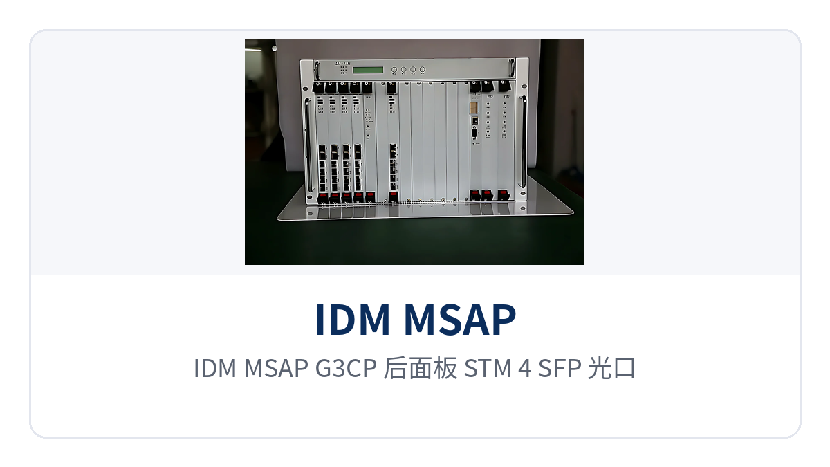
Figure 2: IDM MSAP-G3CP rear panel close-up of STM-4 SFP optical ports, STM-1 FC optical ports, and E1 interface layout
How to Use the E1 Interface 75Ω/120Ω Options and PCM30/32 Channel-Associated Signaling
The E1 interface impedance is selected according to on-site cabling: 75Ω corresponds to coaxial cable and BNC connectors, and 120Ω corresponds to balanced twisted pair interfaces. The two impedances are determined at the time of ordering; whichever type the existing PCM equipment at the site uses, the newly connected E1 interface is configured to match, with no need to add an impedance converter midway.
E1 lines are organized in the PCM30/32 frame structure, with 32 time slots per frame. TS0 carries frame alignment and alarms, TS16 carries channel-associated signaling (CAS), and the remaining 30 time slots carry 64 Kbps voice or data. Channel-associated signaling is passed along with the voice time slots, so voice channel status does not occupy a separate common channel.
When interfacing with existing PCM switching equipment, voice channels can intercommunicate as long as the frame structure, line coding, and signaling format are consistent. Before cutover, verify the time slot allocation against the site voice channel list; reconfiguration involves only cross-connect and time slot parameters, not changes to on-site cabling. During verification, align the time slot table of the opposite end with the local cross-connect configuration item by item, and switch only the connection relationships within the cutover window.
How to Rack-Mount the Dual Power Supply Input and Wide-Temperature Chassis
Power is supplied through two inputs, AC220V and DC-48V. Communications equipment rooms take AC mains power, while DC sites take -48V basic power; select and connect according to site conditions. Overall power consumption does not exceed 150 W, so the power supply capacity and heat dissipation margin of a standard cabinet are sufficient.
The operating temperature is -10℃ to +50℃, and the relative humidity is 0 to 95% (non-condensing). The chassis is rack-mounted in a 19-inch rack, with dimensions of 482×309×132 mm. Where equipment room air conditioning conditions along the line are inconsistent and the day-night temperature difference is large, this temperature range covers the environmental conditions of conventional unattended stations.
Typical Application Scenarios
The IDM MSAP-G3CP 622M optical port SDH multi-service access platform mostly appears as an access or aggregation node in electric power private networks, rail transit communication, and military and government private networks. The three types of scenarios differ in their requirements for optical power margin, power supply format, and interface type, so trade-offs are made according to their respective priorities during configuration.
Electric Power Private Network: Weak Optical Links in the Strong Electromagnetic Environment of Substations
The communications equipment rooms of substations and switching stations have strong electromagnetic interference. Optical cables are laid along high-voltage corridors with many splice points, and the link ends are often in a weak optical state. The IDM MSAP-G3CP connects directly to the superior substation with a 622M optical port and 40Km single-mode transmission; its receiver sensitivity is better than -32dBm, and the link still works when the received optical power falls to around -30dBm.
E1 interfaces are connected via 75 Ω coaxial to relay protection and telecontrol channels, and dispatch voice channels intercommunicate with the switch through PCM30/32 channel-associated signaling. One unit carries both dispatch telephone and telecontrol data, so the substation side no longer needs a separate transmission device for each of the two services.
Rail Transit Communication: Large Temperature Differences and Mixed Power Supply Conditions in Equipment Rooms Along the Line
Equipment rooms along rail transit lines are distributed at stations and sections, with inconsistent air conditioning conditions and both AC and DC power supplies. The IDM MSAP-G3CP has an operating temperature of -10℃ to +50℃, dual power supply inputs supporting AC220V and DC-48V, and dimensions of 482×309×132 mm, so it can be rack-mounted directly in the station integrated cabinet.
Inter-station liaison telephone runs over FXO/FXS analog voice channels, monitoring data over V.24 and codirectional 64K interfaces, and Ethernet service over FE ports. Services at stations along the line are aggregated at the central station through STM-4 optical ports, and chain or ring networking can be selected according to the line route.
Military and Government Private Networks: Long Cabling Distances and Tight Optical Power Budgets
Sites in military and government private networks are sparsely distributed and widely spaced, and optical cable laying distances often approach the upper limit of the equipment's optical power budget. The 622M optical port of the IDM MSAP-G3CP transmits directly over 40Km on a single-mode link, with receiver sensitivity better than -32dBm, so the link remains reliable under weak optical conditions; sites farther away can be extended by replacing with long-distance optical modules.
Within a private network, existing telephone networks and data networks coexist. E1 trunks, analog voice channels, and V.35 data can be accessed in the same chassis and sent to the command center over optical paths. Dual power supply inputs let AC equipment rooms and DC sites use the same model, unifying spare parts and O&M procedures. On this basis, Raytrans can provide SDH equipment selection and networking configuration for government private network optical fiber communication solutions and military emergency communications vehicle solutions.
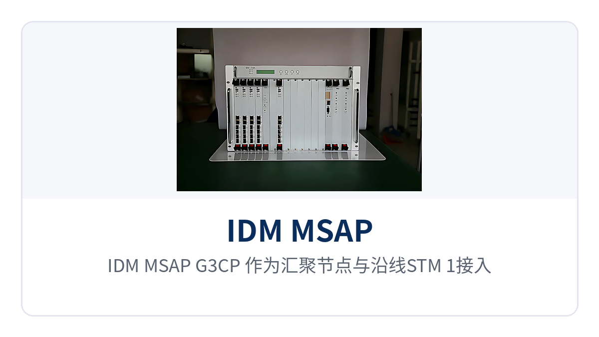
Figure 3: Schematic of IDM MSAP-G3CP as an aggregation node forming a ring network with STM-1 access stations along the line, and the service flow of E1 trunks and Ethernet
Conclusion
The IDM MSAP-G3CP 622M optical port SDH multi-service access platform packs STM-4 and STM-1 dual-rate optical interfaces, 40Km single-mode transmission, and 75 Ω/120 Ω selectable E1 access into one 19-inch chassis, together with receiver sensitivity better than -32dBm and AC220V/DC-48V dual power supply inputs. As an SDH equipment manufacturer, Raytrans positions this SDH equipment in its optical transmission equipment and MSTP product showcase as a multi-service carrying platform for access and aggregation nodes.
This configuration can centrally carry voice, data, and Ethernet services at the access and aggregation nodes of electric power private networks, rail transit communication, and military and government private networks. The equipment room side no longer needs a separate transmission device for each type of service, and cabinet space and supporting power supply are reduced accordingly.
Before deployment, verify the number of E1 channels, the number of analog voice channels, the Ethernet bandwidth, and the optical port rate against the site service list, and determine the number of service cards and the optical module model accordingly. Once the link distance and on-site cable impedance are confirmed, write the correspondence between the optical port rate and the number of service cards into the configuration sheet, and commissioning can be completed in one pass.