IDM MSAP-G2CP SDH Multi-Service Access Platform
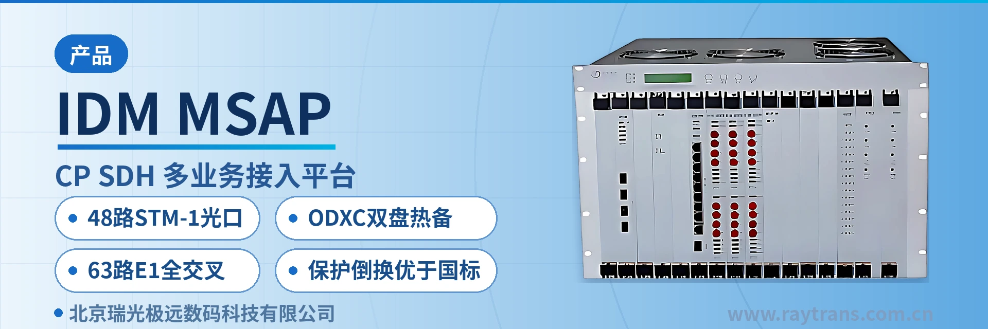
48 STM-1 optical interfaces, dual ODXC active/standby hot standby, 63-channel E1 full cross-connect
The IDM MSAP-G2CP SDH equipment is a new generation product based on SDH technology launched by our company in response to market demand. It can provide access for multiple services, supporting up to 12 STM-1 uplink interfaces and 36 optical interfaces downstream. Board types include: E1-USER board, ETH-USER board, PD board, gigabit optical switching board, ODXC board, CP-21/42E1 board, EOSEOP board, 64K-USER board, etc. The unit adopts a modular card-based structure, and different quantities and types of tributary optical boards can be configured according to actual needs.
IDM MSAP-G2CP is a 48-port STM-1 optical interface SDH multi-service access platform developed by Beijing Ruiguang Jiyuan. It is an SDH device for the private network market, used to aggregate voice, data, video, and E1 services from dispersed remote sites over an SDH transmission network. The unit adopts a modular card-based structure, provides up to 12 STM-1 uplink interfaces upward and 36 optical interfaces downward, totaling 48 optical interfaces at STM-1 rate. It can be used as an ADM or TM device and is a representative product showcase of Raytrans on its optical transmission equipment product line.
A common challenge at the central end of a private network is that remote sites are dispersed and the service volume at a single site is small but varied: dispatch telephone, telecontrol E1, video, and office Ethernet belong to different systems. IDM MSAP-G2CP collects these services into the same set of SDH transmission channels. The central end faces only one network element for each remote site, with configuration, alarms, and service scheduling handled centrally, and both the number of devices and the variety of spare parts in the equipment room are reduced. As an SDH equipment manufacturer, Raytrans has integrated MSTP capabilities into this platform, which can carry the multi-service access requirements in government private network optical fiber communication solutions and is also suitable for mobile deployment scenarios such as military emergency communications vehicle solutions.
Key Specifications at a Glance: 48 optical interfaces at STM-1 rate · 12 uplinks and 36 downlinks · dual ODXC boards in active/standby hot standby · 16 STM-1 full cross-connect per board · 63-channel E1 full cross-connect signaling gateway · 4 Ethernet ports plus 20 groups of E1 per PD board
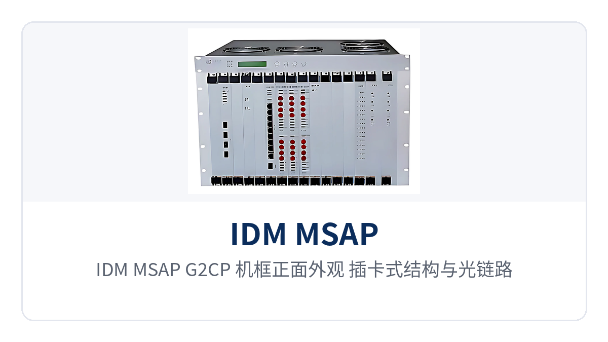
Figure 1: Front view of the IDM MSAP-G2CP chassis, modular card-based structure and optical link indicator LEDs
What kind of device is the 48-port STM-1 optical interface SDH multi-service access platform?
An SDH multi-service access platform refers to a centralized device that uses the SDH frame structure as the transmission foundation and multiplexes services such as E1, Ethernet, low-speed data, and video into VC-12 containers for unified transport. As a typical SDH device, the chassis of IDM MSAP-G2CP is not bound to a single service; its modular card-based structure determines its access capacity: by inserting different types and numbers of tributary boards, the same device presents different interface combinations at different sites, and the flexibility of the product showcase is reflected precisely here.
How many optical directions a device can carry depends on the number of ODXC boards and optical interface boards that can be inserted into the chassis. IDM MSAP-G2CP provides 12 STM-1 uplink interfaces upward to access the transmission plane and 36 optical interfaces downward to connect remote access devices, totaling 48 optical interfaces at STM-1 rate. When the number of remote sites increases, downlink optical interface boards are added site by site, and the uplink direction is uniformly aggregated according to the ring network or chain network structure of the transmission plane.
48 STM-1 optical interfaces for uplink and downlink, a single unit aggregating dispersed remote sites—in engineering terms, this means the central equipment room does not need a separate aggregation device for each remote link. In star networking, the central end needs only one chassis, with one access-type MSAP device at each remote site; voice, data, video, and E1 services are aggregated site by site, and link capacity expansion only requires adding optical interface boards.
How does the modular card-based structure allow service boards to be configured as required?
The unit can be inserted with service boards such as E1-USER boards, ETH-USER boards, PD boards, gigabit optical switching boards, ODXC boards, CP-21/42E1 boards, EOSEOP boards, and 64K-USER boards. How many E1 channels and how many Ethernet channels are in the site service list, and whether 64K low-speed data is needed, can be calculated board by board. The initial investment is implemented according to the current service volume, and future capacity expansion only requires adding boards without changing the chassis.
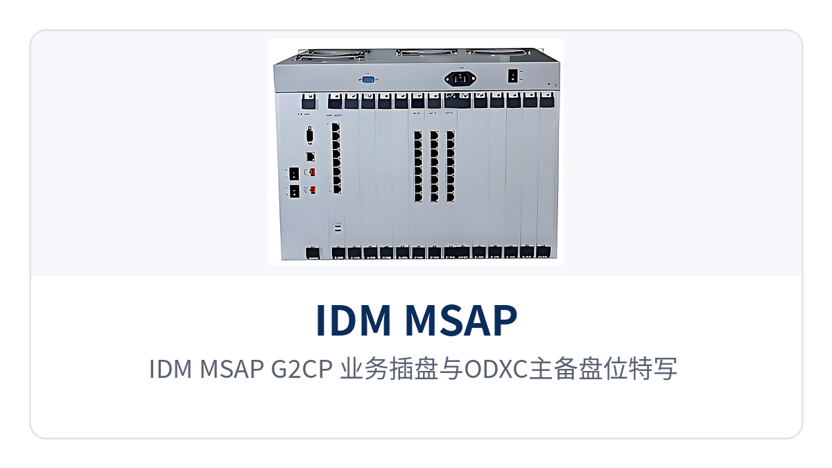
Figure 2: Close-up of the IDM MSAP-G2CP service plug-in boards and ODXC active/standby card slots, including the E1-USER board and PD board interface areas
How do dual ODXC boards in hot standby and 63-channel E1 full cross-connect ensure uninterrupted aggregation?
Dual ODXC boards in active/standby hot standby, with automatic or manual switchover, and network management uninterrupted. The two ODXC boards led out from the backplane simultaneously undertake the aggregation function of Ethernet network management and serial port network management, operating as active and standby. When the active board is abnormal, automatic switchover can be performed, or manual switchover can be specified on site, and the network management channel is not lost with a single board failure.
Each ODXC board has a full service cross-connect capability of 16 STM-1 and supports alarm reporting and alarm records. The cross-connect granularity covers all VC-12, and service add/drop and pass-through are allocated within the same cross-connect table. When a site adds services, it is sufficient to adjust the time slots without changing the optical path routing and optical module configuration.
63-channel E1 full cross-connect signaling gateway, unified access of channelized E1 and Ethernet. The SGX signaling gateway board provides a full cross-connect capacity of 63 E1 channels and schedules the E1 channelized services on the PD board and E1-USER board within the same chassis. Signaling channels and data channels therefore do not require two separate sets of equipment, and the rack positions and patch panel occupancy at the central end are reduced accordingly.
Channelized E1 and Ethernet service access is the basic capability of this platform: E1 is mapped into VC-12 at 2.048 Mbps granularity, and Ethernet services are carried by bundling VC-12 bandwidth. The two types of services occupy their own time slots on the same batch of STM-1 optical paths without preempting each other. Each PD board provides 4 Ethernet interfaces and 20 groups of E1 interfaces, and the narrowband and broadband services of remote sites can be proportioned board by board.
How are synchronization timing and protection switching configured?
Synchronization timing adopts a synchronous equipment timing source (SETS): it can track the optical line timing source or accept an external synchronization input, and provides an external synchronization output to downstream devices. When line timing or external timing fails, or when SSM indicates degraded quality, the timing source automatically performs switchover according to the failure and SSM, and the inter-station clock does not lose lock due to the failure of a single timing source.
For protection, path protection and subnetwork connection protection (SNCP) are supported, and the protection switchover time is better than international standards. When an optical cable is damaged by external forces or an optical module fails, services continue to be transmitted along the backup channel or the other direction of the ring network, and dispatch telephone and telecontrol E1 channels remain available during the switchover.
What functions can this platform provide?
The functions of IDM MSAP-G2CP fall into five aspects: optical transmission, cross-connection scheduling, service access, synchronization timing, and operation and maintenance. The table below lists the function items and descriptions one by one, and during selection, check them line by line against the site service list. For interface capabilities not listed in the table, the manufacturer's technical documentation and commercial confirmation shall prevail.
| Function | Description |
|---|---|
| 48 optical interfaces at STM-1 rate | 12 STM-1 uplink interfaces upward and 36 optical interfaces downward, totaling 48 optical interfaces at STM-1 rate; a single chassis carries the central aggregation of a star private network |
| Dual roles of ADM and TM | It can serve as an add-drop multiplexer to add/drop circuits at intermediate stations of chain and ring networks, or as a terminal multiplexer to send services into an existing SDH transmission network |
| Dual ODXC boards in active/standby hot standby | The two ODXC boards led out from the backplane undertake Ethernet network management and serial port network management aggregation, active and standby, with automatic or manual switchover, and the network management channel is uninterrupted |
| 16 STM-1 full cross-connect per board | Each ODXC board has a full service cross-connect capability of 16 STM-1 and supports alarm reporting and alarm records |
| VC-12 full cross-connection | Supports cross-connection of all VC-12, and E1 and Ethernet services are added/dropped and passed through at VC-12 granularity |
| Channelized E1 and Ethernet access | Provides channelized E1 and Ethernet service access; the two types of services occupy their own time slots on the same batch of optical paths without preempting each other |
| PD board interface capability | Each PD board provides 4 Ethernet interfaces and 20 groups of E1 interfaces; narrowband and broadband services at remote sites are proportioned board by board |
| SGX signaling gateway board | Full cross-connect capacity of 63 E1 channels; signaling channels and E1 service channels are scheduled within the same chassis |
| Synchronization timing (SETS) | Optionally tracks the optical line timing source or external synchronization input, provides external synchronization output, and automatically performs timing source switchover according to failure or SSM |
| Path protection and subnetwork connection protection | Supports path protection and subnetwork connection protection (SNCP), and the protection switchover time is better than international standards |
Key specifications and interface specifications
The parameters in the table below are taken from the product technical documentation and are provided for checking during networking design and equipment selection. The recommended checking order is to first look at the total number of optical interfaces and the uplink/downlink allocation, then the cross-connect capability and signaling gateway capacity, and finally confirm the service board proportioning and synchronization mode. For items not given in the documentation, such as power supply, overall power consumption, and enclosure dimensions, fill in according to the commercial confirmation result, and do not infer from similar equipment.
| Item | Parameter/Specification | Description/Applicable Conditions |
|---|---|---|
| Total optical interfaces | 48 optical interfaces at STM-1 rate | Uplink and downlink combined, configured board by board |
| Uplink optical interfaces | 12 STM-1 uplink interfaces | Access the transmission plane or an upper-level aggregation node |
| Downlink optical interfaces | 36 optical interfaces | For remote access devices, added according to the number of sites |
| Device role | ADM or TM | Add/drop circuits at intermediate stations of chain and ring networks, or serve as a terminal multiplexer |
| Cross-connect capability per ODXC board | Full service cross-connect of 16 STM-1 | Supports alarm reporting and alarm records |
| Cross-connect granularity | All VC-12 | E1 and Ethernet services are scheduled at VC-12 granularity |
| Signaling gateway board | SGX board, full cross-connect of 63 E1 channels | Signaling channels and E1 service channels are scheduled in the same chassis |
| PD board interfaces | 4 Ethernet interfaces, 20 groups of E1 interfaces | Interface proportioning of each PD board |
| Service board types | E1-USER board, ETH-USER board, PD board, gigabit optical switching board, ODXC board, CP-21/42E1 board, EOSEOP board, 64K-USER board, etc. | Selected according to the site service list; capacity expansion adds boards without changing the chassis |
| Synchronization timing | SETS, tracking the optical line timing source or external synchronization input | Provides external synchronization output, with automatic switchover according to failure or SSM |
| Network management | Ethernet network management and serial port network management aggregation | Undertaken by two ODXC boards, operating active and standby |
| Protection mode | Path protection, subnetwork connection protection | Protection switchover time is better than international standards |
| Power supply mode and overall power consumption | not yet recorded in the knowledge base | Subject to the manufacturer's technical documentation and commercial confirmation |
| Enclosure dimensions and operating temperature | not yet recorded in the knowledge base | Subject to the manufacturer's technical documentation and commercial confirmation |
Differentiated value: what problems does the 48-port STM-1 optical interface platform solve in private networks?
When private networks purchase central-end optical transmission equipment, the judgment points usually fall on three places: how many optical directions a single unit can carry, whether cross-connect and network management will fail due to a single board failure, and whether E1 and Ethernet can be carried in the same chassis. The table below maps capabilities to on-site value item by item, and the procurement list and acceptance documents can directly use the same set of wording.
| Differentiated capability | Value for private network users |
|---|---|
| 48 optical interfaces at STM-1 rate | A single unit aggregates dispersed remote sites: 12 uplinks plus 36 downlink optical interfaces; multi-site services of a star private network are aggregated into one chassis, without configuring an aggregation device for each link |
| Dual ODXC boards in active/standby hot standby | Network management uninterrupted: two ODXC boards, active and standby, undertake network management aggregation, with automatic or manual switchover; a single board failure does not affect central-end monitoring of the entire network |
| 63-channel E1 full cross-connect signaling gateway | Unified access of channelized E1 and Ethernet: 63-channel E1 full cross-connect and VC-12 granularity cross-connect are in the same chassis; signaling, E1 leased lines, and Ethernet services share one set of transmission channels |
| Modular card-based on-demand capacity expansion | Controllable initial investment: service boards are configured according to the site service list; capacity expansion only adds boards without changing the chassis and optical paths, and upgrades and maintenance do not affect in-service services |
The trade-off relationship among the four capabilities is clear: the total number of optical interfaces determines the aggregation scale, cross-connect and network management redundancy determine whether the central end becomes a single point, and the types of service boards determine what an SDH device can connect. Checking item by item according to site conditions is closer to actual operating results than a general comparison of unit parameters.
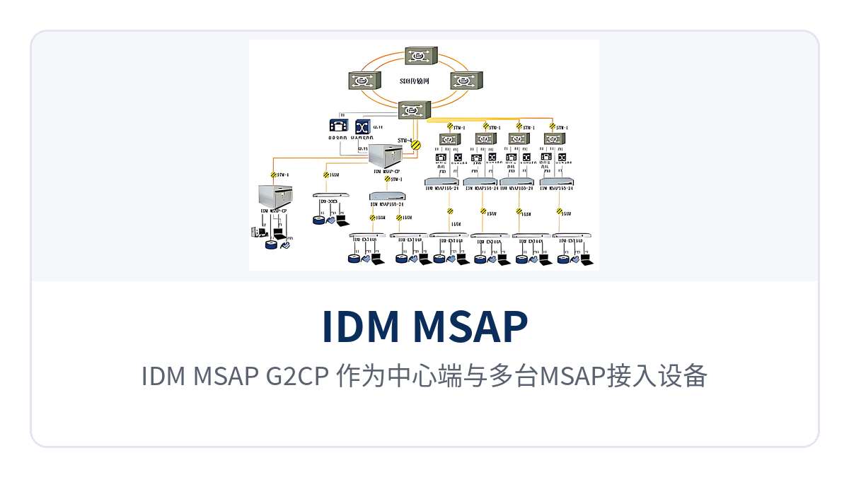
Figure 3: Topology diagram of IDM MSAP-G2CP as the central end forming a star private network with multiple MSAP access devices
Typical Application Scenarios
IDM MSAP-G2CP usually acts as the central end in private networks, aggregating service traffic from remote stations downstream through its tributary optical interfaces and connecting upstream to the transmission plane through 12 STM-1 uplink interfaces. The three scenarios below describe deployment approaches according to industry service structures; the actual configuration is subject to the site service list.
Dispatch Center and Substation Aggregation in Electric Power Private Networks
Substations, switching stations, and power supply stations are dispersed, and each site needs to upload dispatch telephone, telecontrol E1 channels, and video surveillance at the same time. Deploying transmission equipment at every site would quickly fill up the racks and wiring in the central equipment room. On the dispatch center side, IDM MSAP-G2CP aggregates services from all stations with a single chassis, with E1 added and dropped at VC-12 granularity and Ethernet services carried by the ratio of 4 Ethernet interfaces to 20 E1 interfaces on the PD board.
Star networking lets each remote link occupy its own tributary optical interface. When a link undergoes inspection or an optical cable failure occurs, the impact is limited to that station, and services at other stations are aggregated as usual. The dual ODXC boards run in active/standby mode, with the network management channel taken over by the standby board, so the dispatch end can still see alarms from all stations across the network during a single board failure. This is a common implementation of star private network aggregation in the electric power industry.
Stations Along the Line and Depots in Rail Transit Private Networks
Services at stations along the line, depots, and section equipment rooms in rail transit are mainly E1 channels and Ethernet. Official telephone, signal monitoring, and video surveillance have high continuity requirements, and different services must not interfere with each other in the transmission segment. IDM MSAP-G2CP carries the two service types separately through channelized E1 and Ethernet service access, each occupying independent VC-12 time slots, so traffic growth in one service type does not squeeze the other.
There are many stations along the line and service volume varies greatly from station to station, which is where the card-based structure proves its value: stations with more services are equipped with more E1-USER boards and PD boards, while stations with fewer services are equipped with fewer boards, so the same model covers sites of different scales. Path protection and subnetwork connection protection (SNCP) allow services to be transmitted along the backup direction when a single-segment optical cable fails, with a protection switching time better than international standards.
Aggregation of Dispersed Units in Military and Government Private Networks
Remote units, duty posts, and storage areas in military and government private networks are dispersed, with service types covering voice, data, video, and E1 leased lines, limited on-site maintenance resources, and varying equipment room conditions. As the central end, IDM MSAP-G2CP aggregates the services of all units into the same set of SDH channels, with unified configuration and monitoring in the central equipment room, while remote stations only need to insert boards according to the service list.
The 63-channel E1 full cross-connect signaling gateway undertakes centralized scheduling of signaling and service channels in such scenarios, so no separate cross-connect equipment is needed for E1 channels. Dual ODXC active/standby hot standby with automatic or manual switchover keeps the central end's network management online when a single board is abnormal, reducing on-site troubleshooting trips caused by monitoring interruption.
Conclusion
As a 48-channel STM-1 optical port SDH multi-service access platform, IDM MSAP-G2CP packs 12 uplink interfaces, 36 tributary optical interfaces, dual ODXC active/standby hot standby, a 63-channel E1 full cross-connect signaling gateway, and card-based service card configurations into a single chassis, connecting upstream to the transmission plane and aggregating voice, data, video, and E1 services from dispersed remote stations downstream.
For star private network aggregation nodes in electric power private networks, rail transit private networks, and military and government private networks, where service types are many, sites are dispersed, and rack positions are limited, a single central-end SDH device handles optical direction aggregation, cross-connection scheduling, and network management redundancy, and the number of devices and points of failure on the site side are reduced accordingly. The specific number of optical interface boards, service board ratio, and synchronization mode should be determined after confirmation with the project service list and the technical documentation of the manufacturer Raytrans.