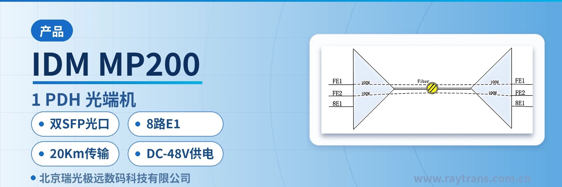
IDM MP200-8E1 PDH Optical Multiplexer
Dual SFP optical ports, 8 E1, 2 Fast Ethernet, single-fiber one-unit access, E1-saving optical multiplexer and
The IDM MP200-8E1 optical multiplexer provides two SFP optical interfaces, eight E1 circuits, and two 100M wire-speed Ethernet interfaces in a single unit. It offers an SNMP network management interface and comprehensive alarm monitoring functions, with high integration, low power consumption, stable performance, and ease of use.
IDM MP200-8E1 is an 8-channel E1 dual-optical-port PDH optical multiplexer developed by Beijing Ruiguang Jiyuan Digital Technology Co., Ltd. (Raytrans). A single unit integrates 2 groups of SFP optical interfaces, 8 E1 circuits and 2 100M wire-speed Ethernet interfaces, and is used to carry E1 leased lines and two types of 100M data services simultaneously over one optical fiber link. It is a typical multi-service optical multiplexer product.
As an 8-channel E1 dual-optical-port PDH optical multiplexer, the device is deployed in pairs in point-to-point mode: one end connects the existing services at the site and converts them into optical signals, and the other end restores the E1 and RJ45 interfaces as they are. Only one optical fiber link is occupied between the two sites, and the cabling and number of devices within each site are reduced accordingly. This PDH optical multiplexer is suitable for scenarios such as government private network optical fiber communication solutions, military emergency communications vehicle solutions and smart mining communication solutions. As a professional optical multiplexer manufacturer, Raytrans provides complete selection and deployment descriptions in its product showcase.
Key Specifications at a Glance: Dual SFP optical ports · 8 E1 channels (ITU-T G.703, 75 Ω/120 Ω) · 2 100M wire-speed Ethernet ports · 20 km transmission · receiver sensitivity better than -32 dBm · DC -48 V power supply optional · overall power consumption ≤10 W
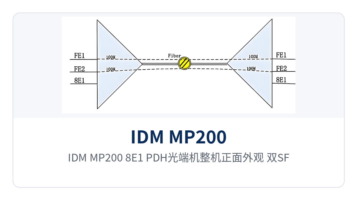
Figure 1: Front view of the IDM MP200-8E1 PDH optical multiplexer, showing the layout of the dual SFP optical ports and the operation and alarm indicator LEDs
What Is an 8-Channel E1 Dual-Optical-Port PDH Optical Multiplexer
An 8-channel E1 dual-optical-port PDH optical multiplexer refers to PDH equipment that provides 8 E1 transparent channels and 2 100M Ethernet channels in one enclosure and uplinks through SFP optical interfaces. The E1 side is processed in accordance with ITU-T G.703 at 2.048 Mbps with HDB3 line coding and PCM30/32 frame structure, and the time slot content is transparently transmitted as it is; the Ethernet side transmits and receives in accordance with IEEE 802.3, and the operating mode supports full/half duplex and adaptive.
The two types of services occupy separate channels inside the device and do not contend with each other, yet share the same link over the optical cable. The E1 channel does not parse or rewrite the original frame structure, so the digital trunk equipment, PCM multiplexer and dispatch automation devices at the far end operate with their original parameters, and there is no need to re-check each service during cutover; the Ethernet channel forwards at port wire speed, so IP services such as surveillance and office traffic can be connected directly.
The two optical interfaces of the IDM MP200-8E1 are pluggable SFP structures; single-mode is the standard configuration, and multi-mode modules can be selected for short-distance cabling. The receive/transmit rate is 250M, and the receive/transmit wavelength is 1310 nm/1550 nm. The SFP slots make it easy to replace optical modules according to link distance and to stock spare parts, and the same device can be adjusted between the 20 km standard configuration and longer-distance configurations without replacing the complete unit. As a multi-service optical multiplexer for private network access, this model is often listed as a typical configuration in the PDH product showcase.
What On-Site Problems Do Dual SFP Optical Ports, 8 E1 Channels and 2 100M Ports Solve
Private network access points often face three things at once: many types of services to be connected in one pass, limited cabinet rack positions and optical cable cores, and weak on-duty staffing at remote sites. The IDM MP200-8E1 packs dual SFP optical ports, 8 E1 channels and 2 100M Ethernet ports into the same device. The three differentiated capabilities below correspond to these three things respectively, and can be checked item by item against the on-site service list during selection.
| Differentiated Capability | Value to Private Network Access Points |
|---|---|
| Dual SFP optical ports + 8 E1 channels + 2 100M ports, meeting multi-service private network access in one unit | One optical fiber link carries 8 E1 leased lines, two 100M Ethernet channels and SNMP network management at the same time, so the site no longer needs to configure E1 optical multiplexers and media converters separately by service type, and the number of rack positions, power supply modules and cabling is reduced accordingly |
| 20 km single-mode transmission and receiver sensitivity better than -32 dBm, more stable on weak optical links | The standard configuration provides 20 km repeaterless transmission, and normal reception is maintained as long as the receive side is not lower than -32 dBm, so sections with many optical cable splices or high attenuation caused by aging lines still have margin, and measured optical power can be used to judge whether additional optical modules are needed |
| AC 220 V/DC -48 V dual power supply optional, overall power consumption ≤10 W | AC mains power and communications DC power are configured separately according to site conditions, and the overall power consumption is ≤10 W, so unattended sites and small equipment cabinets can be installed without capacity expansion, with low heat generation during long-term operation and controllable temperature rise inside the cabinet |
Which Services One Device Connects: Functions and Interfaces at a Glance
The functions of the IDM MP200-8E1 cover four categories: optical transmission, E1 access, Ethernet multiplexing and O&M monitoring. The role and applicable conditions of each capability are listed in the table below. During selection and acceptance, check the number of interfaces, interface type and network management mode row by row against the site service list, so as to avoid discovering interface mismatches only after the complete unit arrives.
| Function | Description |
|---|---|
| Dual SFP optical ports | Provides 2 groups of SFP optical interfaces; single-mode is the standard configuration and multi-mode is optional; receive/transmit rate 250M, receive/transmit wavelength 1310 nm/1550 nm, transmit optical power -12~-6 dBm, receiver sensitivity better than -32 dBm |
| 8-channel E1 transparent transmission | Provides 8 E1 channels in one unit, bit rate 2.048 Mbps, line code HDB3, compliant with ITU-T G.703, impedance 75 Ω/120 Ω optional, frame structure PCM30/32, channel-associated signaling, time slot content transparently transmitted as it is |
| 2 100M wire-speed Ethernet ports | Provides 2 groups of 100M wire-speed Ethernet interfaces, RJ45 type, transmission rate 10M/100M/1000M adaptive, compliant with IEEE 802.3, operating mode supports full/half duplex and adaptive |
| SNMP network management interface | An SNMP network management interface can be provided; together with panel alarm indication, the central side can remotely view device and link status, so there is no need to send personnel to the remote site for confirmation every time |
| Local/remote alarm monitoring | Provides comprehensive alarm monitoring; when the optical path is interrupted or an E1 channel is abnormal, both the local end and the remote end give indications, and the difference between the two indications can be used to determine whether the fault lies in the device, the optical cable or the remote end |
| 20 km repeaterless transmission | The standard model has a repeaterless transmission distance of 20 km; beyond this distance, long-distance optical modules can be installed to achieve optical fiber transmission over longer distances |
| Dual power supply formats | Supports AC 220 V and DC -48 V power supply, configured separately according to site power conditions, with overall power consumption ≤10 W |
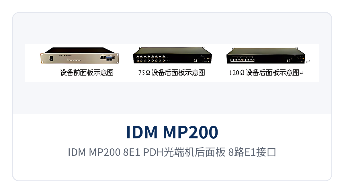
Figure 2: Rear panel of the IDM MP200-8E1 PDH optical multiplexer, showing the layout of the 8 E1 interfaces, 2 100M Ethernet ports and dual power supply terminals
Key Specifications: Optical Interface, E1, Ethernet and Power Supply
The specifications are listed in four parts: optical interface, E1 channels, Ethernet interfaces, and power supply and environment. The values are taken from the original product documentation. The link budget is calculated from the transmit optical power and receiver sensitivity, and the site power capacity is calculated from the overall power consumption; both are taken from the specifications in the table to avoid a second order change.
| Item | Parameter/Specification | Description/Applicable Conditions |
|---|---|---|
| Optical interface type | SFP | Pluggable optical module, selected according to distance and optical fiber type |
| Fiber mode | Single-mode (multi-mode optional) | Single-mode for medium and long distances between stations, multi-mode for short distances within a station |
| Receive/transmit rate | 250M | 8 E1 channels and 2 100M Ethernet channels share the bandwidth of this optical path |
| Receive/transmit wavelength | 1310 nm/1550 nm | Determined by the selected SFP optical module |
| Transmit optical power | -12~-6 dBm | Transmit-side value for link attenuation calculation |
| Receiver sensitivity | Better than -32 dBm | Normal reception is maintained as long as the received optical power is not lower than this value |
| Transmission distance | 20 km | Standard optical module; long-distance optical modules can be installed for longer distances |
| Number of E1 channels | 8 | One unit accesses 8 E1 services |
| E1 bit rate | 2.048 Mbps | Rate of a single E1 channel |
| E1 line code | HDB3 | Compliant with ITU-T G.703 |
| E1 impedance | 75 Ω/120 Ω | Unbalanced coaxial or balanced interface, selected according to the peer device |
| E1 frame structure and signaling | PCM30/32, channel-associated signaling | Transparent transmission mode, without changing the original time slot content |
| Ethernet interface | RJ45 | 2 groups of 100M wire-speed ports |
| Ethernet transmission rate | 10M/100M/1000M adaptive | Compliant with IEEE 802.3, full/half duplex/adaptive |
| Network management interface | SNMP | Can be provided, for centralized viewing of site status at the central side |
| Power supply mode | AC 220 V/DC -48 V | The two formats are selected according to site conditions |
| Overall power consumption | ≤10 W | Load calculated according to site power capacity |
| Operating temperature | -10 ℃~+50 ℃ | Equipment room and non-constant-temperature equipment cabinet environments |
| Relative humidity | 0~95% (non-condensing) | Normal operation under non-condensing conditions |
| Dimensions | 482×309×132 mm | Rack installation in a 19-inch standard chassis |
How to Calculate Link Margin for 20 km Single-Mode Transmission and Receiver Sensitivity Better Than -32 dBm
The link margin is estimated as "transmit optical power minus receiver sensitivity": the transmit side is -12~-6 dBm and the receive side is better than -32 dBm, and subtracting the two values gives an available attenuation margin of about 20~26 dB. In engineering practice, the loss per kilometer of optical cable and the connector loss of each splice point and adapter are further subtracted, and only the remainder is the margin left for line aging and construction deviations.
Calculating by this formula is closer to on-site conditions than selecting directly by the nominal 20 km. Receiver sensitivity better than -32 dBm means that normal reception is maintained as long as the received optical power is not lower than this value, so weak optical links with many optical cable splices, excessively long patch cord slack or long service life still have room to cope, and the link is more stable. On site, use an optical power meter to measure the received optical power and then compare it with this specification; this is more reliable than estimation by experience.
For the standard model, conventional single-mode optical modules are sufficient within 20 km; when the line distance exceeds 20 km or the measured attenuation is relatively high, install long-distance optical modules to achieve optical fiber transmission over longer distances, without replacing the complete unit and service interfaces. Multi-mode modules are recommended only for short-distance cabling within a station, and should be checked against the actual optical cable type and distance during selection. This is exactly the advantage of the SFP slots: replacing the module adjusts the transmission distance, while the service configuration and peer devices remain unchanged. In the product showcase of this PDH optical multiplexer series, Raytrans provides the above configuration options for private network users; whether for a government private network optical fiber communication solution, a military emergency communications vehicle solution or a smart mining communication solution, the appropriate SFP modules can be selected according to on-site optical cable conditions.
How Dual SFP Optical Ports, 8 E1 Channels and 2 100M Ports Are Multiplexed over the Same Fiber
The calculation for multiplexing over the same fiber is straightforward: 8 E1 channels total 8×2.048 Mbps≈16.4 Mbps, 2 100M Ethernet channels total about 200 Mbps at port wire speed, and all services total about 216 Mbps, which is still within the capacity of the 250M optical port, so they can travel over the same optical path. The Ethernet side forwards independently per port, and the two 100M services do not contend for forwarding capability. This approach of packing multiple services into one PDH optical multiplexer is exactly the typical capability of multi-service optical multiplexer products in the product showcase.
E1 and Ethernet occupy their own channels and time slots inside the device, are uniformly encapsulated for transmission over the optical path, and are demultiplexed and restored at the far end. In this way, one optical fiber link carries all services, so old lines with tight fiber cores do not need capacity expansion, and sites do not need to stack multiple devices by service type, which simplifies the variety of spare parts and the amount of cabling.
The two groups of SFP optical ports leave adjustable room for the site: the two paths can be connected to two directions respectively, or one backup optical fiber channel can be reserved. When the main optical path is scheduled for maintenance or is unexpectedly interrupted, switching the patch cord to the backup channel allows operation to continue, and the switching action is completed inside the cabinet without waiting for new fiber cores to be laid. The backup optical port normally carries no services, and optical modules are stocked by the same model; after on-site replacement, the device automatically restores reception.
Typical Application Scenarios
The IDM MP200-8E1 is mainly deployed in point-to-point mode: one unit is placed at the service site and one at the central equipment room or centralized control station, the two ends are directly connected by optical fiber, and the E1 and Ethernet services are restored at the central side and then connected back to the existing transmission and switching equipment. The device is suitable for private network access points where optical fiber resources are tight and the service types are mainly E1 leased lines and 100M data.
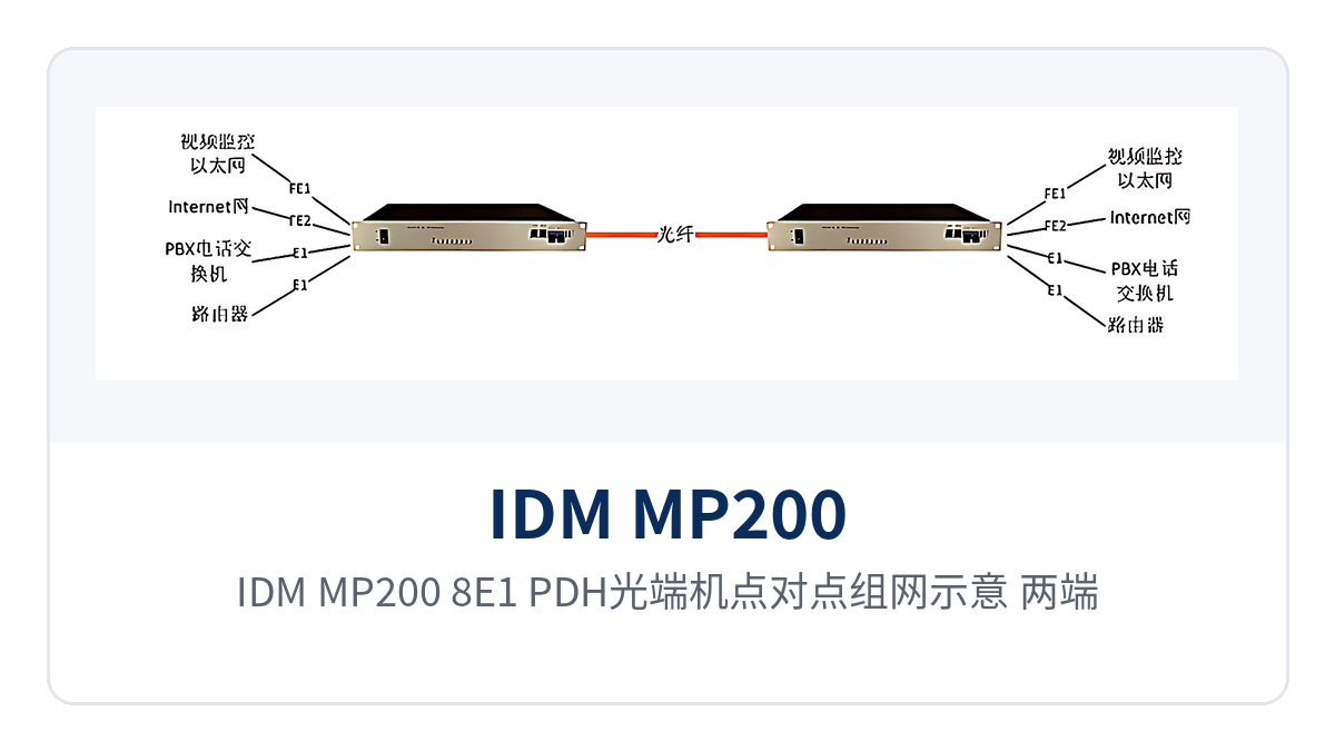
Figure 3: IDM MP200-8E1 PDH optical multiplexer point-to-point networking schematic; both ends are interconnected through SFP optical ports and then restore 8 E1 channels and 2 Fast Ethernet channels
Electric Power Distribution and Substation Communication: Dispatch Data E1 and In-Station Fast Ethernet Data Backhauled over the Same Cable
Substations, switching stations and distribution stations need to simultaneously transmit dispatch automation, relay protection signals and in-station IP data. Most sites are unattended, and both equipment room space and the number of fiber cores are limited. The IDM MP200-8E1 aggregates 8 E1 channels and 2 Fast Ethernet channels into one device: telecontrol and protection information travel over E1 channels, while video surveillance and in-station office each occupy one Fast Ethernet port, and only one optical fiber link is used between stations.
The communication power supply at electric power sites is mostly DC -48 V, while station service power is AC 220 V. The two formats are configured per station, the overall power consumption is ≤10 W, and existing power supply capacity can usually carry the load directly. The operating temperature is -10 ℃ to +50 ℃, suitable for site equipment cabinets without constant-temperature conditions. By comparing the alarm indications at both ends, on-duty personnel can locally narrow a failure down to the device, the optical cable or the opposite end.
Communication Along Rail Transit Lines: Service Channel Extension Between Stations and Section Equipment Rooms
Between stations and section equipment rooms of metro and conventional railways, train operation telephone, signaling system E1 channels and video surveillance data need to be transmitted. Station spacing is several kilometers, and equipment room rack positions are tight. The IDM MP200-8E1 is deployed site by site according to site distribution; each station accesses services nearby and backhauls them to the central equipment room over the trunk optical fiber, so a station no longer needs a separate optical multiplexer for each type of service.
Transparent transmission of the 8 E1 channels extends the existing channels of the signaling system as they are, and the station side can complete access without replacing existing equipment. The 2 Fast Ethernet ports carry surveillance and office services separately, so maintenance on one does not affect the other. Power supply formats vary along the line; AC and DC power supply modes can be selected per station, and the variety of spare parts is reduced accordingly.
Military and Public Security Private Networks: Multi-Service Access for Unattended Sites and Temporary Command Posts
Public security checkpoints, duty posts and temporary command posts in the field often have no ready transmission resources and need E1 leased lines, internal networks and low-speed data paths established within a short time. The IDM MP200-8E1 is deployed as a pair; once the optical fiber is connected, E1 and RJ45 interfaces are restored, the opposite-end equipment configuration remains unchanged, and the link relationship is clear, making it easy to temporarily adjust node locations according to the mission. Such deployment is also often incorporated into the selection reference of military emergency communications vehicle solutions and government private network optical fiber communication solutions.
Classified and non-classified services are connected to the two Fast Ethernet ports separately, and the network boundary is separated by ports, so there is no need to rely on switch access control policies. The available SNMP network management interface allows the central side to remotely check the status of remote stations; together with local-end/opposite-end alarm indications, sites with limited duty personnel can also complete fault diagnosis at the center.
Installation and Commissioning: From Optical Path Verification to Service Acceptance
On-site commissioning proceeds in six steps, from optical path calculation and interface wiring to power supply connection and commissioning; each step has a verifiable checkpoint. Complete them in order before moving to the next step, so as to avoid rework after the unit is fully installed when link margin is insufficient or interface impedance does not match.
- Verify the optical path: use standard single-mode optical modules within 20 Km; for longer distances or when measured attenuation is high, install long-distance optical modules, and calculate the link margin according to a transmit optical power of -12 to -6 dBm and a receiver sensitivity better than -32 dBm.
- Connect the optical fiber: insert the SFP modules in the slot direction until seated, pair the receive and transmit fibers correctly, leave sufficient bend radius on the patch cords, and cap unused optical ports with dust caps.
- Connect E1: select 75 Ω coaxial (BNC) or 120 Ω balanced (RJ45) wiring according to the opposite-end equipment, verify the receive/transmit direction of each of the 8 channels, and route E1 cables separately from power cables to avoid strong-current interference.
- Connect Ethernet: connect the two Fast Ethernet ports by service domain; port rates are adaptive among 10M/100M/1000M; after wiring, check whether the port indicator LEDs and negotiated rates match the opposite end.
- Connect power: connect AC 220 V or DC -48 V according to site conditions; observe positive and negative polarity for DC wiring; after power-on, check whether the power indicator and overall power consumption are within ≤10 W.
- Commissioning and acceptance: check E1 alarms and Ethernet link status channel by channel, confirm remote status at the central side through SNMP network management, and connect formal services only after confirming there are no abnormalities.
Two items are easily missed at the acceptance stage: first, the alarm indications at both ends must be compared; an abnormality at one end is mostly an optical path problem, while simultaneous abnormalities at both ends require checking the optical modules and the optical fiber. Second, record the measured received optical power for archiving, so that later line upgrades or optical cable relocation can be judged against it to see whether the margin is still sufficient. For the 8 E1 channels, it is recommended to label each channel with its service name and check against the labels during cutover and inspection to reduce mistaken unplugging.
Conclusion
As an 8-channel E1 dual-optical-port PDH optical multiplexer, the IDM MP200-8E1 packs 2 groups of SFP optical ports, 8 E1 channels and 2 wire-speed 100M Ethernet channels into the same 19-inch enclosure, and one optical fiber link completes same-cable backhaul of E1 leased lines and Fast Ethernet data. The device is deployed as a point-to-point pair; E1 transparent transmission does not change the existing frame structure, and after restoration at the central side it connects directly back to the original transmission and switching equipment. For project owners currently screening optical multiplexer manufacturers, the product showcase performance of this type of multi-service optical multiplexer in scenarios such as electric power and rail transit can serve as a reference basis for selection from the Raytrans series.
On the power supply side, both AC 220 V and DC -48 V formats are supported, with overall power consumption ≤10 W; on the optical path side, 20 Km single-mode transmission is supported with receiver sensitivity better than -32 dBm; together with local-end/opposite-end alarms and SNMP network management, it is suitable for access nodes of electric power distribution networks, rail transit lines and military and public security private networks, and can also extend to underground and above-ground site interconnection in smart mining communication solutions. During selection, first count the number of E1 channels and the Fast Ethernet port service domains at the sites, then calculate the link margin and confirm the power supply format, and the configurations at both ends can be aligned.