IDM MINICP Optical-Electrical Integrated Transmission Equipment
STM 4 STM 1 dual-rate optical port, one chassis mixed insertion of E1, Ethernet, 64K narrowband
The complete SDH equipment can be inserted with STM-4/STM-1 boards, G3-8EOS board, G3-2GE board, G3-ETHUSER board, G3-42E1 board, G3-16E1DXC, G3-NMS-ETH board, and various 64K narrowband subscriber access boards, etc. Its functions are the same as G3CP, only the dual-board mutual backup function is weaker.
The IDM MINICP dual-rate optical port optical-electrical integrated transmission equipment is a set of optical-electrical integrated transmission equipment based on SDH technology, developed by the SDH equipment manufacturer Beijing Ruiguang Jiyuan Digital Technology Co., Ltd. It is used for the access, multiplexing and transmission of voice, data and Ethernet services at the private network access layer, and is a representative SDH equipment in the access layer product showcase.
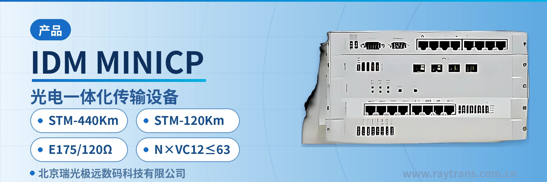
The equipment accommodates both SDH optical line units and various tributary service card slots in a 19-inch 3U card-based chassis. Upward, it accesses the transmission network through STM-4 or STM-1 optical ports; downward, it outputs E1, gigabit and Fast Ethernet, telephone, 64K data and other services. An access site does not need to deploy a separate device for each type of service, which fully reflects the integrated advantage of SDH equipment at the access layer.
The two optical channels differ in rate and distance specifications: the STM-4 optical port has a receive/transmit rate of 622.08Mbps and a standard single-mode configuration transmission distance of 40Km; the STM-1 optical port has a receive/transmit rate of 155.52Mbps and a standard single-mode configuration transmission distance of 20Km. The receiver sensitivity of both optical port tiers is better than -32dBm, and long-distance optical modules can be optionally installed to extend the link further. This optical transmission equipment can adapt to scenarios such as government private network optical fiber communication solutions and military emergency communications vehicle solutions, and supports MSTP multi-service transmission applications.
Key Specifications at a Glance: STM-4 40Km · STM-1 20Km · E1 75/120Ω · N×VC12≤63 · 622.08Mbps and 155.52Mbps dual rate · 3U card-based · ≤150W · AC220V/DC-48V
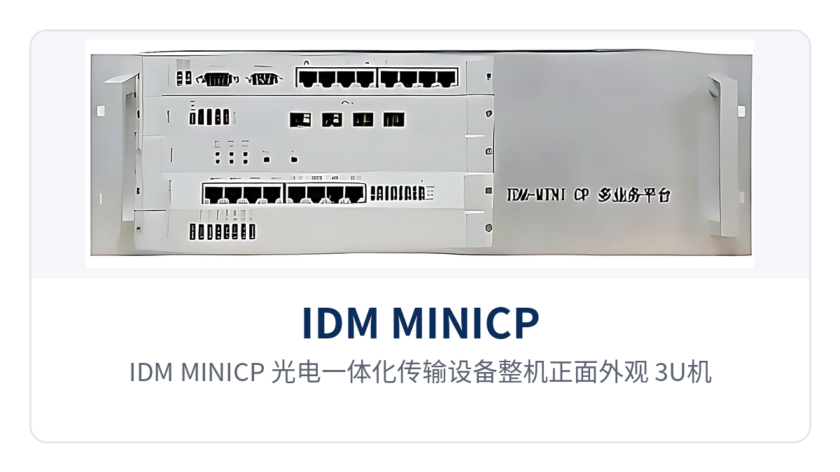
Figure 1: IDM MINICP optical-electrical integrated transmission equipment front appearance, 3U chassis card slots and optical link alarm indicator LEDs
What Is a Dual-Rate Optical Port Optical-Electrical Integrated Transmission Equipment: One Chassis Handles Both Transmission and Access
Optical-electrical integrated transmission equipment is equipment that installs SDH optical transmission units and PCM narrowband access units into the same chassis. The line side performs multiplexing, cross-connection and dispatching of optical signals, while the tributary side packs telephone, data and Ethernet services into VC-12 containers and carries them over optical fiber. As a compact SDH equipment, it can complete the full presentation from transmission to access on a single product showcase platform.
The chassis of the IDM MINICP adopts a card-based structure, with front cards and rear cards configured in pairs; which cards are inserted determines which services the site can output. The STM-4 card and STM-1 card determine the rate of the external optical channel, while the EOS card, 2GE card, Ethernet user card, 42-channel E1 card, 16-channel E1 cross-connect card and 64K narrowband user card determine the types of services delivered. This SDH equipment manufacturer usually presents the fully configured capability in the product showcase in the form of a card configuration list.
The same chassis can be configured as a terminal multiplexer, an add-drop multiplexer, or a mixture of both, and the networking can be point-to-point, chain network, ring network, star or tree. When a site is upgraded from a chain network to a ring network, it is only necessary to configure one optical port card in each direction and add time slots; the chassis and service cards remain unchanged. This feature gives this SDH equipment flexible networking adaptability in government private network optical fiber communication solutions and military emergency communications vehicle solutions.
Function Items and Corresponding Capability: Check the Card Configuration List in One Table
The functions of the unit are divided into five sections: transmission, cross-connection, access, timing and network management. The following table lists the functions and their roles item by item. When configuring cards, check the card types and quantities against the site service list; the table gives the upper limit of fully configured capability, the actual number of interfaces is determined by the card configuration, and margin is reserved according to the capacity expansion plan.
| Function | Description |
|---|---|
| SDH optical transmission | STM-4 optical port receive/transmit rate 622.08Mbps, single-mode transmission 40Km; STM-1 optical port receive/transmit rate 155.52Mbps, single-mode transmission 20Km; modules at both ends are paired by wavelength and distance |
| VC-12 and 64K cross-connection | The STM-4 cross-connect and aggregation card provides non-blocking cross-connection of 32×32 VC-4, 2016×2016 VC-12 and 512×512 64K time slots; the STM-1 cross-connect and aggregation card provides 441×441 VC-12 and 1024×1024 64K time slots |
| EOS Ethernet access | The G3-8EOS card provides independent Ethernet aggregation interfaces, with bandwidth configured as N×VC12 (N≤50), and can connect to remote single-E1 bridges and EOS Ethernet services |
| Gigabit Ethernet access | The G3-2GE card provides 2 groups of gigabit Ethernet services, each group with 1 optical and 1 electrical interface, with bandwidth configured as N×VC12 (N≤63) |
| Fast Ethernet access | The G3-ETHUSER card provides Ethernet subscriber interfaces, compliant with IEEE802.3, with full/half duplex adaptive |
| E1 tributary access | The G3-42E1 card provides 42 E1 tributaries, and the G3-16E1DXC card provides 16 E1 channels with cross-connection; a fully configured unit can output 168 E1 channels |
| 64K narrowband services | Various 64K narrowband user cards carry FXO/FXS, magneto, EM2/4-wire, codirectional 64K, V.24 and V.35 services; a fully configured unit can output 120 telephone channels and 120 V.24 interfaces |
| Synchronous timing | The clock source can be line clock, external clock 2Mbit/s or 2MHz, or free-run, organized according to the existing network timing links |
| Network management | The G3-NMS-ETH card provides an Ethernet management channel and, through the NetGuard network management system, implements configuration, alarm and performance management, with SNMP support |
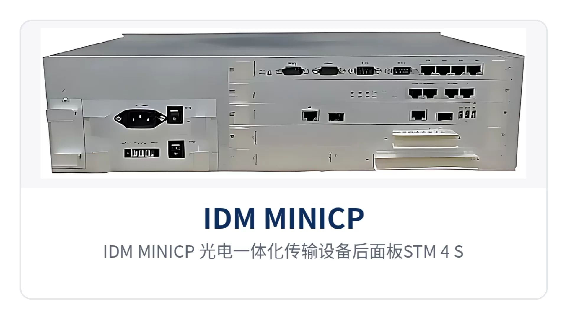
Figure 2: IDM MINICP optical-electrical integrated transmission equipment rear panel STM-4 and STM-1 optical interfaces and E1 and Ethernet service card interface layout
How to Check the Key Specifications: Optical Ports, E1, Ethernet and Power Supply
The order for checking specifications is to first calculate the optical power budget, then count the E1 directions and service points, and finally confirm the power supply format and cabinet space. The values in the following table are taken from the product technical documentation; engineering calculations are subject to the on-site optical fiber attenuation, number of splice points and cabling conditions, and items not listed in the table are subject to the manufacturer's technical documentation and commercial confirmation.
Optical Interfaces and Transmission Distance
| Item | Parameter/Specification | Description/Applicable Conditions |
|---|---|---|
| Interface type (STM-4) | SFP, single-mode (multimode optional) | Optical modules are selected by distance and wavelength and are pluggable for replacement |
| Receive/transmit rate (STM-4) | 622.08Mbps/622.08Mbps | STM-4 line rate, with identical receive and transmit rates |
| Receive/transmit wavelength | 1310nm/1550nm | Modules at both ends are paired by wavelength |
| Transmit optical power | -12~-6dBm | Used to calculate the optical link budget |
| Receiver sensitivity | Better than -32dBm | Covers splicing and optical cable aging margin |
| Transmission distance (STM-4) | 40Km | Standard single-mode configuration; long-distance optical modules can be optionally installed for longer transmission distance |
| Interface type (STM-1) | FC, single-mode (multimode optional) | Interfacing with existing 155M optical transmission equipment |
| Receive/transmit rate (STM-1) | 155.52Mbps/155.52Mbps | STM-1 line rate, can be configured online to operate at STM-1 rate |
| Transmission distance (STM-1) | 20Km | Standard single-mode configuration; long-distance optical modules can be optionally installed for longer transmission distance |
E1 Interfaces and Existing Network Compatibility
| Item | Parameter/Specification | Description/Applicable Conditions |
|---|---|---|
| Bit rate | 2.048Mbps | Standard E1 line rate |
| Line code | HDB3 | Consistent with domestic E1 line format |
| Standard protocol | Supports ITU-T G.703 | Can be directly connected to SDH, PDH and PCM equipment tributaries |
| Impedance | 75Ω/120Ω | Coaxial or balanced access is selected according to on-site cabling; changing the connection only involves interface adapters |
| Frame structure | PCM30/32 | 32 time slots per frame, with 30 time slots carrying services |
| Signaling | Channel-associated signaling | Voice channel status is transmitted together with the voice time slots |
Ethernet, Voice and Data Interfaces
| Item | Parameter/Specification | Description/Applicable Conditions |
|---|---|---|
| Ethernet interface | RJ-45, transmission rate N×VC12 (N≤50) | EOS Ethernet card, compliant with IEEE802.3, full/half duplex/adaptive |
| Ethernet interface (gigabit) | RJ-45, transmission rate N×VC12 (N≤63) | Gigabit Ethernet card, each group with 1 optical and 1 electrical GE interface |
| Telephone interface | FXO/FXS, audio 300Hz~3400Hz | Compression ITU G.711 A-law, three-element complex impedance 200Ω+560Ω//0.1μF, loop current 20mA per channel |
| Magneto and EM2/4-wire | Audio 300Hz~3400Hz, impedance balanced 600Ω | Compression ITU G.711 A-law, return loss no less than 18dB |
| Codirectional 64K interface | Line code G.703 standard, bit rate 64Kbps, balanced 120Ω | Fully compliant with ITU-T G.703 recommendation |
| V.24 interface | Asynchronous ≤9600bps; synchronous 64Kbps | Electrical characteristics compliant with CCITT V.28 protocol |
| V.35 interface | n×64Kbps (n=0~31), RJ-45 | Compliant with ITU-T V.35 recommendation, terminal interface compliant with ISO2593 |
Power Supply, Power Consumption and Installation Environment
| Item | Parameter/Specification | Description/Applicable Conditions |
|---|---|---|
| Power supply mode | AC220V/DC-48V | Selected according to on-site power conditions for AC equipment rooms and DC distribution panel sites |
| Overall power consumption | ≤150W | Power drawn by the unit when fully configured with cards |
| Operating temperature | -10℃~+50℃ | Communications equipment rooms, substation communication rooms and field cabinets |
| Relative humidity | 0~95% (non-condensing) | Normal operation under non-condensing conditions |
| Dimensions | 482×309×132(mm) | Length×Depth×Height, 19-inch 3U rack installation |
How Dual-Rate Optical Ports and E1 Impedance Determine Site Configuration
The STM-4 and STM-1 optical port tiers are assigned according to the site's position in the network: central stations or aggregation stations use STM-4 optical ports, whose 622.08Mbps line capacity can accommodate more VC-12s, so that a single optical channel can collect the services of multiple subordinate access stations; access stations use STM-1 optical ports, whose 155.52Mbps is sufficient to carry the station's E1 and Ethernet services. As an SDH equipment manufacturer, Raytrans clearly marks the applicable station types for these two SDH optical port tiers in the product showcase, making it convenient for design institutes to select SDH equipment according to site hierarchy.
The distance specification determines whether a repeater equipment room is needed. The STM-4 optical port has a standard single-mode transmission distance of 40Km, so long-distance links between substations and dispatch centers can be directly connected; the STM-1 optical port has a standard single-mode transmission distance of 20Km, covering the common spacing between adjacent rail transit stations and switching stations along the line. Sites exceeding the standard configuration only need to be fitted with long-distance optical modules, with the chassis and time slot configuration unchanged.
E1 impedance is a practical item for existing network interfacing. Both 75Ω coaxial and 120Ω balanced access modes comply with G.703. When interfacing with existing PCM equipment, PDH optical multiplexers and digital dispatching exchanges, select according to the peer tributary impedance; changing the connection only involves interface adapters, without changing the chassis or service cards.
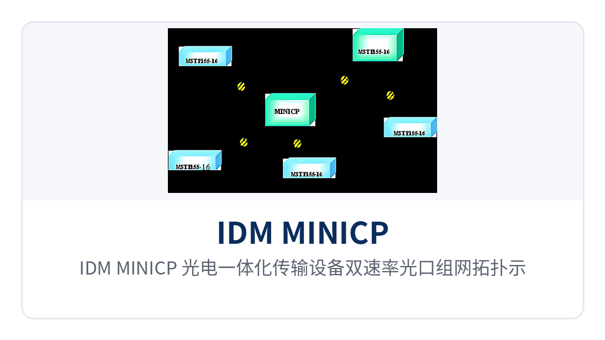
Figure 3: IDM MINICP optical-electrical integrated transmission equipment dual-rate optical port networking topology diagram, central station STM-4 aggregation and access station STM-1 chain network
Typical Application Scenarios
IDM MINICP targets the private network access layer, with electric power private networks, rail transit, and military and government private networks as three typical deployment positions. The service point lists differ across the three types of sites, but the board configuration approach is the same: first determine the optical port rate and distance, then the number of E1 directions and telephone channels, and finally select the power supply format according to the on-site power source. Raytrans lists board configuration recommendations by scenario in its product showcase of optical transmission equipment, making it easy to cross-reference during early-stage project selection of SDH equipment.
Electric Power Private Network: STM-4 40Km and E1 75Ω Direct Connection for Long-Distance Substation Links
Between a substation and the dispatch center, dispatch telephone, telecontrol data, protection channels, and in-station surveillance run simultaneously; each service type forms its own network within the station before being sent upstream in a centralized manner. IDM MINICP uses STM-4 optical ports to connect substations within 40Km directly to the aggregation station, so no repeater equipment room is needed within the station, and the power supply and duty for repeater sites are eliminated.
During implementation, configure the boards according to the in-station service list: protection and safety control channels use E1 tributaries, dispatch telephone uses FXO/FXS cards, telecontrol data uses co-directional 64K or V.24 interfaces, and office and video use Ethernet boards. E1 tributaries are connected according to the 75 Ω coaxial or 120 Ω balanced wiring of existing PCM equipment in the existing network, and the opposite-end equipment does not need to be replaced when cutting over existing 2M channels.
Rail Transit: 20Km Coverage for Section Stations and Flexible Networking with Dual-Rate Optical Ports
Stations along a rail line are spaced far apart, and power supply access and maintenance windows in the sections are limited, so optical transmission equipment should minimize repeaters. STM-1 optical ports with single-mode transmission over 20Km can cover the common section length between adjacent stations; the line's central station is equipped with STM-4 optical ports according to the service aggregation volume. The two rates are selected by station type within the same series of chassis, unifying spare parts and O&M practices.
Official telephone, section telephone, broadcast audio, and monitoring data within the station are connected to telephone cards, audio cards, and Ethernet boards respectively, each occupying independent VC-12 time slots. During optical cable cutover or inspection in a section, services are delivered along the other direction of the ring network, and the dispatch center does not need to reconfigure time slots site by site.
Military and Government Private Networks: ≤150W Low Power Consumption and AC/DC Dual Power Supply for Field Sites
Power supply conditions at field command posts and unattended equipment rooms vary with the site, with mains power, diesel generators, and -48V DC distribution panels coexisting. IDM MINICP supports both AC220V and DC-48V power supply formats, with overall power consumption ≤150W. The same model can be installed in cabinets with different power supply formats, and cross-site transfer and spare parts stocking are managed under a single model. Raytrans can provide SDH equipment selection support for government private network optical fiber communication solutions and military emergency communications vehicle solutions, with MSTP and SDH dual-mode networking completed within the same chassis.
The service side is configured with boards according to the mission: command voice uses FXO/FXS cards, service data uses V.24 or V.35 interfaces, image backhaul uses gigabit Ethernet boards, and 64K narrowband services and time slot dispatching are completed within the same chassis. The 3U chassis fits into a standard cabinet or a vehicle-mounted rack, and the lifting and wiring workload for mobile deployment decreases with the number of devices.
Conclusion
As a dual-rate optical port optical-electrical integrated SDH device, IDM MINICP uses STM-4 40Km to achieve direct connection of long-distance sites, STM-1 20Km to cover section stations, and E1 75 Ω/120 Ω access to accommodate existing PCM wiring, bringing SDH transmission and 64K narrowband access into a single 3U chassis. Raytrans also provides MSTP networking and SDH equipment selection guidance in its optical transmission equipment product showcase, making it easy to cross-reference configurations for private network projects.
For electric power, rail transit, and military and government private network projects, cabinet space, the number of patch cords, and the variety of spare parts decrease with the number of devices, making the construction and O&M costs of the access layer easier to calculate; the two optical port tiers, STM-4 and STM-1, are selected by station type, and O&M practices remain consistent across the same series of chassis.