IDM M9000 Portable Multimedia Dispatching Exchange
Three-in-one optical transmission, voice switching, and video codec, 10 FXS ports, 10 FXO ports
The IDM-M9000 is a compact portable multimedia dispatching exchange that can integrate SDH communication, mobile phone communication, radio communication, subscriber telephones (FXS), loop-start trunks (FXO), and other communication means. Through advanced digital voice processing technology and network encrypted transmission technology, devices such as intercoms of different frequency bands, VHF/UHF radio sets, HF radio sets, traditional PSTN (public switched telephone network) telephones, IP softphones, and traditional IP phones are seamlessly connected to the dispatch system network.
The IDM M9000 portable multi-standard converged dispatching exchange is a compact integrated dispatching device developed by Beijing Ruiguang Jiyuan Digital Technology Co., Ltd. It is used to connect SDH transmission, mobile phones, HF and VHF/UHF radio sets, FXS subscriber telephones, FXO loop-start trunks, and IP phones to the same dispatch network, achieving unified access for audio and video dispatching and converged communications. A single device simultaneously handles optical transmission, voice switching, and video codec, so that telephones, radios, and images at a field command post can be aggregated in one place, providing integrated bearer capability for command and dispatch.
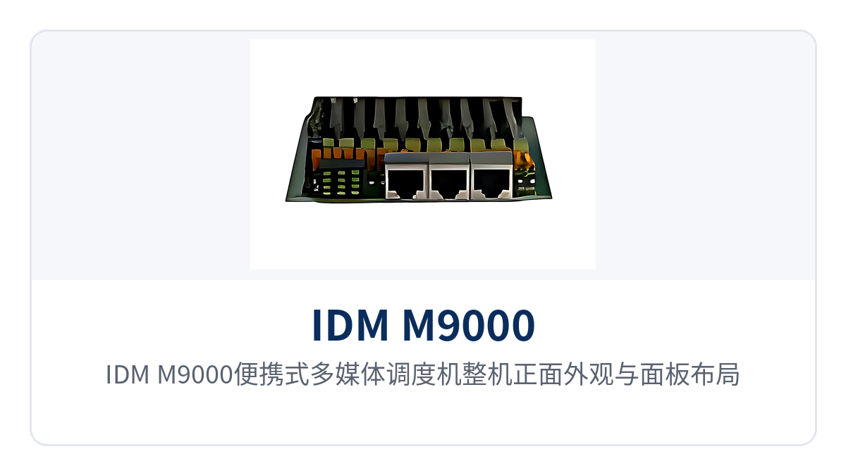
Figure 1: Front view and panel layout of the IDM M9000 portable multimedia dispatching exchange
The unit adopts a 19-inch 3U card-based chassis, with service interfaces configured by board; 10 FXS interfaces, 10 FXO interfaces, and 8 E1 interfaces can coexist in the same chassis. As a compact multimedia dispatching exchange, field sites no longer need to stack multiple single-function devices, and cabinet space, power supply circuits, and duty points are reduced accordingly, making product showcase and on-site deployment more convenient.
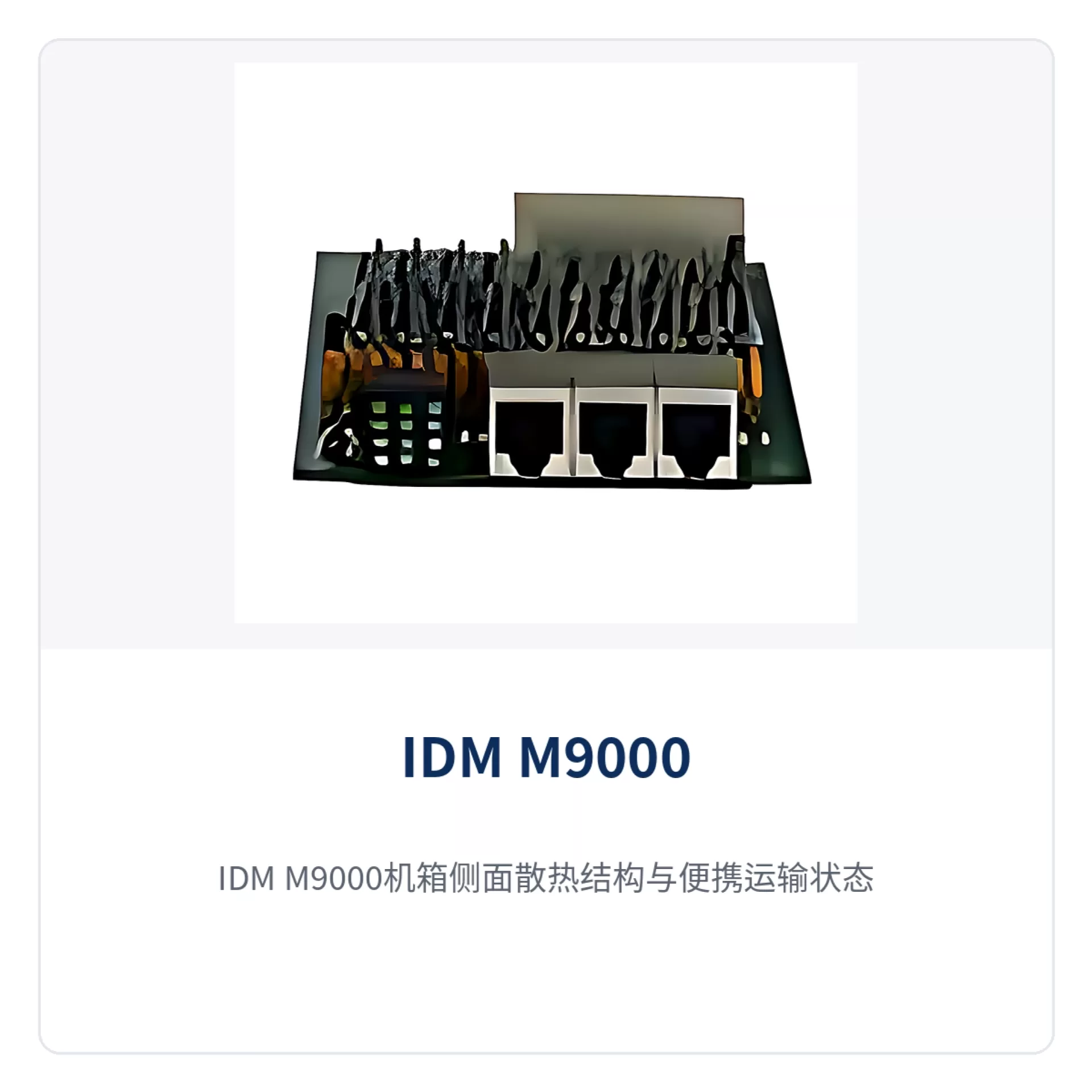
Figure 2: Side heat dissipation structure and portable transport state of the IDM M9000 chassis
Key specifications at a glance: 10 FXS · 10 FXO · 8 E1 · 4-channel 1080P video codec · 155M PDH optical port · 8 RS232/RS485/RS422
Why can one portable dispatching exchange replace multiple sets of communication equipment at a field site?
The reason is that the interface types are consolidated into the same chassis instead of being distributed across multiple devices. The IDM M9000 can converge multiple communication means such as SDH communication, mobile phone communication, radio communication, subscriber telephones (FXS), and loop-start trunks (FXO). Voice switching and transmission are completed on the same service link, and one less on-site joint commissioning means one less point of failure. This design, which integrates audio and video dispatching capabilities into a single unit, allows field sites to no longer deploy multiple sets of communication equipment separately.
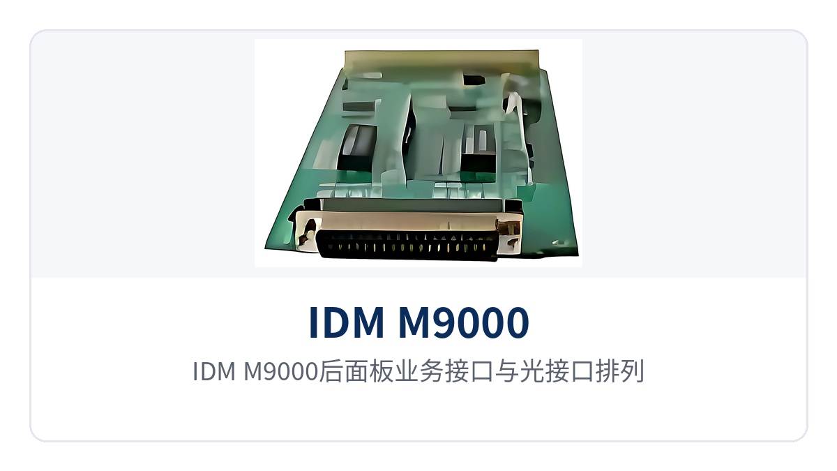
Figure 3: Rear panel service interfaces and optical interfaces of the IDM M9000
Interworking between different standards is supported by two technologies: digital voice processing and encrypted network transmission. Intercoms of different frequency bands, VHF/UHF radio sets, HF radio sets, traditional PSTN telephones, IP softphones, and traditional IP phones can all access the dispatch network by voice. On-duty personnel can call any type of terminal on the same dispatch interface, achieving unified access under converged communications and a product showcase-level interface presentation.
The equipment form factor determines deployment speed. The 3U chassis can be transported in a case; upon arrival, service can be opened by inserting boards according to the on-site interface types, connecting terminals, and powering up for configuration, without separate site work for telephones, video, and data. For tasks with very short time windows, such as temporary training and emergency repair and rescue, whether the system can go online on time directly determines the command and dispatch capability of the command post.
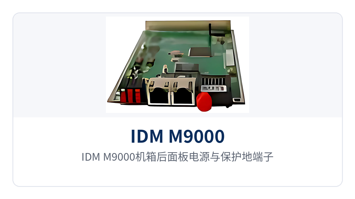
Figure 4: Rear panel power and protective ground terminals of the IDM M9000 chassis
What is this device, and what role does it play in a private network?
The IDM M9000 is a compact portable multimedia dispatching exchange, located between on-site terminals and transmission links. On one side, the device connects telephones, radios, phones, and video terminals; on the other side, it sends services to the remote end through the 155M PDH optical port or E1 interfaces. Voice and images are closed-loop within the private network and do not depend on the public network. As a core node in the converged dispatching system, it also undertakes the front-end access role of the audio and video dispatching and converged communication command and dispatch system.
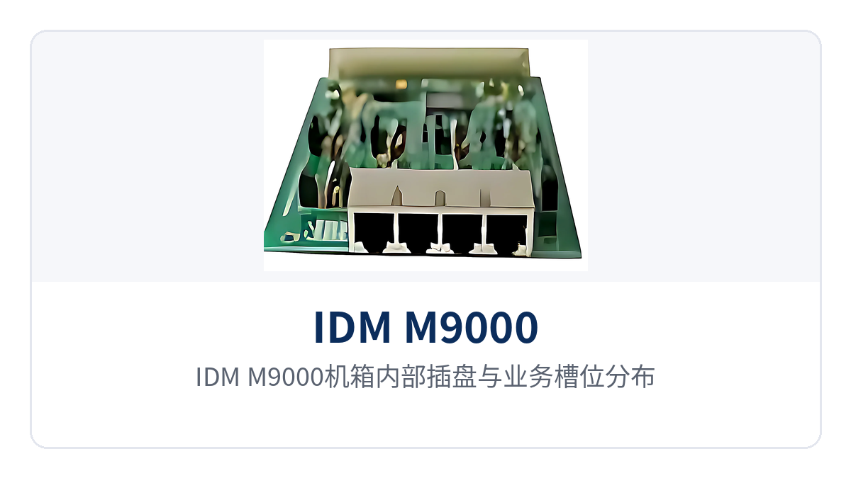
Figure 5: Internal card and service slot distribution of the IDM M9000 chassis
It can be used in three ways in networking. The device can be used standalone to build a small-scale dispatch system, or used with a dispatch console to form an on-site command operator seat, or used as a remote trunking access gateway of a large dispatch system to bring remote radios and phones into central dispatching. Whether for a military emergency communications vehicle solution or a government private network optical fiber communication solution, it can be flexibly deployed as a remote access node.
The chassis structure is a 19-inch 3U card-based type, providing 9 user slots that can accommodate 8FE Ethernet switching cards, 8E1 service cards, PDH service cards, high-definition video codec cards, and various 64 kbit/s service cards. For capacity expansion, simply add or replace boards without replacing the entire unit, and existing terminals and cabling remain unchanged. As a professional command and dispatch system manufacturer, Ruiguang Jiyuan balances the scalability of the multimedia dispatching exchange and the convenience of on-site deployment in this model.
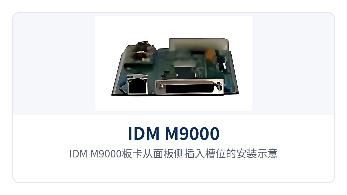
Figure 6: Installation diagram of IDM M9000 boards being inserted into slots from the panel side
How to verify core specifications and board configuration?
The capabilities of the IDM M9000 are determined by the boards inserted in the chassis. The function, board, and parameter tables can be checked item by item, and during selection the board configuration can be derived from the number of on-site interfaces. After configuration is complete, the number of interfaces, transmission bandwidth, and service types are subject to the actual inserted cards. Before ordering, it is recommended to open all three tables for verification. For scenarios undertaking audio and video dispatching and command and dispatch tasks, the board combination must also take into account the access requirements of product showcase signals and converged communication links, ensuring that the multimedia dispatching exchange retains expansion margin at the unit level.
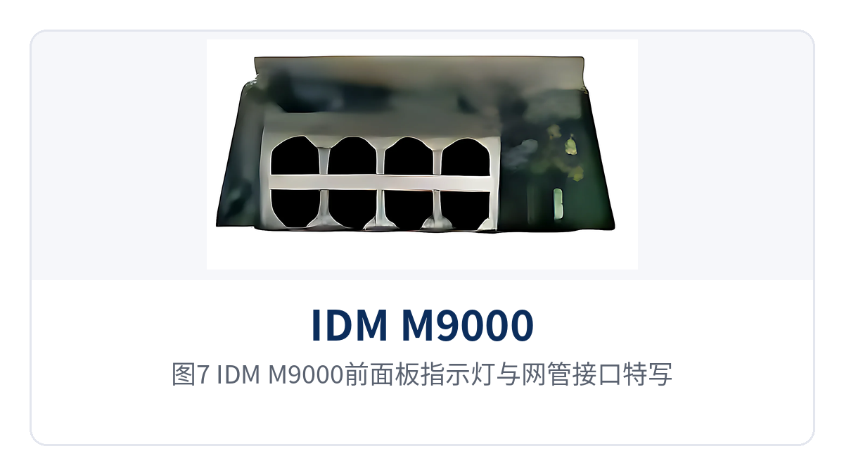
Figure 7: Close-up of front panel indicator LEDs and network management interface of the IDM M9000
Function Overview
| Function | Description |
|---|---|
| Multi-standard voice convergence | Connects FXS subscriber telephones, FXO loop-start trunks, magneto and hotline, E1 digital signaling, and IP phones to the same dispatch network; extensions can dial each other directly, providing a voice foundation for converged dispatching |
| Radio and mobile phone access | Supports wireless radio interfaces such as HF, VHF/UHF, and trunking intercom, as well as GSM/CDMA mobile phone interfaces, achieving duplex voice interworking between wireless terminals and wired terminals to meet on-site interworking requirements of command and dispatch |
| Optical transmission bearer | The 3U-PDH card provides a 155M PDH optical interface and 2 shared Fast Ethernet interfaces; voice, data, and video can be extended to remote stations over optical fiber, adapting to backbone extension of government private network optical fiber communication solutions |
| HD video codec | The 3U-HDVcodec card provides 4-channel 1080P video input and 1-channel 1080P output, occupying 1 EOS channel, with bandwidth configured as NxE1, capable of carrying product showcase and on-site image backhaul |
| Data interface access | The 3U-8V.24 card provides 8 RS232/RS485/RS422 interfaces, carrying low-speed data services such as monitoring acquisition and environmental quantities |
| Ethernet switching | The 3U-8ETH card provides 8 channels of Fast Ethernet switching services; the 9th Fast Ethernet port connects to one of the 4 EOS channels in the SDH |
| Signaling access | The 3U-WG300 card provides 2 channels of local or remote E1 digital signaling access, supporting No.1, No.7, PRI, and V5.2 signaling |
| Universal PCM slots | The 3U-8USER card provides four universal slots that can accommodate 4 dual-channel 64 kbit/s service PCM sub-cards |
3U Board Selection Table
| Board Model | Interfaces and Capabilities | Typical Use |
|---|---|---|
| 3U-10FXS card | Provides 10 FXS interfaces | Connects ordinary telephones and user telephones; the device side provides feed and ringing current |
| 3U-FXO card | Provides 10 FXO interfaces | Connects to the user-side interfaces of automatic private branch exchanges and common battery telephone exchanges |
| 3U-8E1 service card | Provides 8 E1 interfaces | Interworks with existing transmission or switching equipment per the G.703 standard |
| 3U-PDH card | 155M PDH optical interface and 2 shared Fast Ethernet interfaces | Sends local services to the peer station over optical fiber, supporting remote coverage of government private network optical fiber communication solutions |
| 3U-8V.24 card | Provides 8 RS232/RS485/RS422 | Connects monitoring acquisition, environmental quantities, and alarm data |
| 3U-HDVcodec | Four-channel 1080P video input, 1-channel 1080P output, occupying 1 EOS channel, bandwidth NxE1 | On-site image encoding and upload and remote picture restoration, usable for product showcase and video consultation |
| 3U-8ETH card | Provides 8 channels of Fast Ethernet switching services; the 9th Fast Ethernet port connects to one of the 4 EOS channels in the SDH | Video and IP terminal access and uplink to EOS channels |
| 3U-WG300 | Provides 2 channels of local or remote E1 digital signaling access, supporting No.1, No.7, PRI, and V5.2 signaling | Signaling interworking with existing switching equipment, or acting as an exchange |
| 3U-8USER | Four universal slots that can accommodate 4 dual-channel 64 kbit/s service PCM sub-cards | Supplementary slot positions for small-capacity, multi-standard mixed access |
| 3U-8MVOICE | 8 channels of multi-mode 2-wire audio, configurable via network management as FXS, FXO, hotline, ordinary magneto, or 2100 Hz magneto | Legacy private network terminals access according to existing standards |
| 3U-4EM2/4VOX | Provides 4 channels of EM 2/4-wire audio with network-manageable gain control, adjustment step 0.5 dB | Balanced audio and EM signaling interworking |
| 3U-8SY64K | Provides 8 codirectional 64K interfaces | Interworks with existing PCM equipment for codirectional 64K services |
Figure 8: Front panel interfaces and status indication of the 3U-10FXS card
Interface and Performance Parameter Table
| Item | Parameter/Specification | Description/Applicable Conditions |
|---|---|---|
| Chassis structure | 19-inch 3U card-based chassis | Service boards are inserted from the front panel side; board replacement for capacity expansion requires no chassis replacement |
| FXS interface | 10 channels/board | Provided by the 3U-10FXS board; connects to ordinary telephones and user telephones |
| FXO interface | 10 channels/board | Provided by the 3U-FXO board; connects to the subscriber side interfaces of a switch |
| E1 interface | 8 channels/board | Provided by the 3U-8E1 service board; G.703 standard, 2.048 Mbps |
| Optical interface | 155M PDH optical interface | Provided by the 3U-PDH board; the same board includes 2 shared Fast Ethernet interfaces |
| Video interface | 4-channel 1080P input, 1-channel 1080P output | Provided by the 3U-HDVcodec board; transmitted over 1 EOS channel, bandwidth NxE1 |
| Serial interface | 8-channel RS232/RS485/RS422 | Provided by the 3U-8V.24 board; carries low-speed data services |
| Ethernet interface | 8-channel Fast Ethernet switching + 1-channel Fast Ethernet uplink | Provided by the 3U-8ETH board; the 9th Fast Ethernet port connects to one of the 4 EOS channels in the SDH |
| Signaling mode | Signaling System No. 1, Signaling System No. 7, PRI, V5.2 | Provided by the 3U-WG300 board; 2 channels of local or remote E1 digital signaling access |
| Multi-mode audio | 8-channel 2-wire audio, configurable as FXS, FXO, hotline, ordinary magneto, 2100HZ magneto | Provided by the 3U-8MVOICE board; mode is set through the network management system |
| EM audio | 4-channel EM 2/4-wire, gain adjustable through the network management system, step 0.5dB | Provided by the 3U-4EM2/4VOX board; for the gain range, the manufacturer's documentation shall prevail |
| Codirectional 64K | 8 channels | Provided by the 3U-8SY64K board |
| Service configuration | Board service type and audio gain are set through the network management system | The network management system can adjust each channel individually |
As a command and dispatch system manufacturer, Raytrans can also provide supporting recommendations for military emergency communications vehicle solutions and government private network optical fiber communication solutions beyond chassis selection, and the interfacing between the dispatch console and the converged communication command and dispatch system can also be confirmed before ordering, so that the multimedia dispatching exchange meets both converged communication and command and dispatch requirements in actual deployment.
How do 10-channel FXS, 10-channel FXO, and 8-channel E1 coexist in one device?
The three interface types are carried by three independent boards, inserted into different slots of the same chassis and interconnected through the switching and multiplexing unit inside the chassis. The telephone side, trunk side, and digital transmission side each occupy their own board, inserted on site as required, without contending for each other's ports. All three boards can be fully configured at the same time, and the number of interfaces adds up with the number of inserted boards. This design also gives the unit flexible interface expansion capability in audio and video dispatching and converged communication scenarios.
3U-10FXS board: how are 10 subscriber telephones connected
The 3U-10FXS board provides 10 FXS interfaces on a single board, directly connecting ordinary telephones and user telephones, with power feeding and ringing current supplied by the device side. On site, connect the telephone lines to the corresponding ports and label them; no separate subscriber board or telephone power supply is required.
Figure 9: Overall appearance of the 3U-10FXS board and the arrangement of its 10 ports
Calls on the FXS side are completed by the switching function inside the dispatching exchange; extensions can dial each other directly or go out through FXO trunks or E1 signaling. Number plan and call permission are set once during configuration, and adding telephones later only occupies ports without changing the networking structure. For converged dispatching and command and dispatch systems, these subscriber ports are the basic resources for connecting dispatch consoles and on-site telephones.
Figure 10: Close-up of a single FXS port and its wiring sequence label on the 3U-10FXS board
3U-FXO board: how are 10 loop-start trunks interconnected
The 3U-FXO board provides 10 FXO interfaces for connecting the subscriber side interfaces of automatic private branch exchanges, common battery telephone exchanges, and similar equipment, bringing the extensions of existing switches into the dispatch system. Existing telephones and numbers at old sites can continue to be used, and the upgrade only takes place on the interface side.
Figure 11: Overall appearance of the 3U-FXO board and its 10 loop-start trunk ports
When FXO and FXS are paired, they form a complete trunk channel: one end accesses the subscriber line of the peer switch through FXO, and the other end provides the local telephone through FXS. Calls in both directions can use this channel, and the duty operator does not need to switch back and forth between two telephones. This interfacing method is a common way to reuse existing switches in both government private network optical fiber communication solutions and military emergency communications vehicle solutions.
Figure 12: Close-up of the wiring between the 3U-FXO board ports and an existing switch
3U-8E1 service board: how are 8 E1 channels interconnected with existing transmission
The 3U-8E1 service board provides 8 E1 interfaces, interconnected with existing transmission equipment or switching equipment at 2.048 Mbps in accordance with the G.703 standard. An E1 channel can directly carry 64K voice services, or some time slots can be allocated as bearer channels for data and video.
Figure 13: Overall view of the 3U-8E1 service board and the arrangement of its 8 E1 interfaces
When signaling intercommunication is required, add a 3U-WG300 signaling access board. This board provides 2 channels of E1 digital signaling access from the local or remote end, supports Signaling System No. 1, Signaling System No. 7, PRI signaling, and V5.2 signaling, and provides telephone access to the local or remote end or acts as a telephone exchange. As a signaling board commonly configured by command and dispatch system manufacturers, it enables the multimedia dispatching exchange to intercommunicate with existing SPC switching networks.
Figure 14: Close-up of the E1 interfaces and link indication status on the 3U-8E1 service board
Figure 15: Front panel of the 3U-WG300 signaling access board and its E1 signaling interfaces
How is 4-channel 1080P video codec backhauled over an EOS channel?
The 3U-HDVcodec board provides four channels of 1080P video input and 1 channel of 1080P output on a single board. Video enters the EOS channel in encoded form, occupying 1 EOS channel, with bandwidth configured as NxE1. On site, four cameras connect to the same board, and the remote end decodes 1 video image for display and video recording at the command seat, providing intuitive on-site visual support for command and dispatch.
Figure 16: Overall appearance of the 3U-HDVcodec HD video codec board
The Ethernet channel carrying video is provided by the 3U-8ETH board. This board provides 8 channels of Fast Ethernet switching services, and the 9th Fast Ethernet port connects to one of the 4 EOS channels in the SDH. The video stream enters through the camera's switching port and then uplinks to the EOS channel through the 9th port, without contending with voice time slots for resources.
Figure 17: Close-up of the 4-channel 1080P video input and 1-channel output interfaces on the 3U-HDVcodec board
On-demand bandwidth allocation is the practical advantage of this combination. The NxE1 channels occupied by a single video stream can be set according to on-site link capacity; compress video bandwidth when the link is tight, and improve image quality when the link has spare capacity, always guaranteeing voice time slots first during bandwidth planning. The relationship between the number of video channels and bandwidth is calculated once before ordering, avoiding repeated on-site parameter tuning. In audio and video dispatching services, this on-demand allocation mechanism directly affects the transmission quality of product showcase images and on-site backhaul images.
Figure 18: 8 Fast Ethernet switching ports on the 3U-8ETH board and the 9th port uplinking to an EOS channel
Video and voice running in parallel over the same optical link is a common practice for field command posts to send on-site images to the rear. Cameras connect to the switching ports of the 3U-8ETH board, and the encoded video enters the optical link of the 3U-PDH board through the EOS channel; once decoded at the rear, the images can be used for consultation and decision-making. This is also a typical link organization method for video backhaul in converged communication command and dispatch systems.
Figure 19: Networking schematic of video backhaul over an EOS channel on the same link as voice
How do 8 serial ports and a 155M PDH optical port coexist in one device?
The 3U-8V.24 board provides 8 RS232/RS485/RS422 interfaces for accessing low-speed data services such as monitoring acquisition, environmental quantities, and alarm contacts. Serial port data and voice share the cross-connect and multiplexing unit of the same chassis, so on site there is no need to run a separate pair of optical fibers for data or add a serial port server.
Figure 20: Overall view of the 3U-8V.24 board and the arrangement of its 8 serial interfaces
The 3U-PDH board provides a 155M PDH optical interface and 2 shared Fast Ethernet interfaces, sending local services to the opposite site over optical fiber. A pair of optical ports can carry voice, serial port data, and video, and the same set of boards sends all three service types out at once.
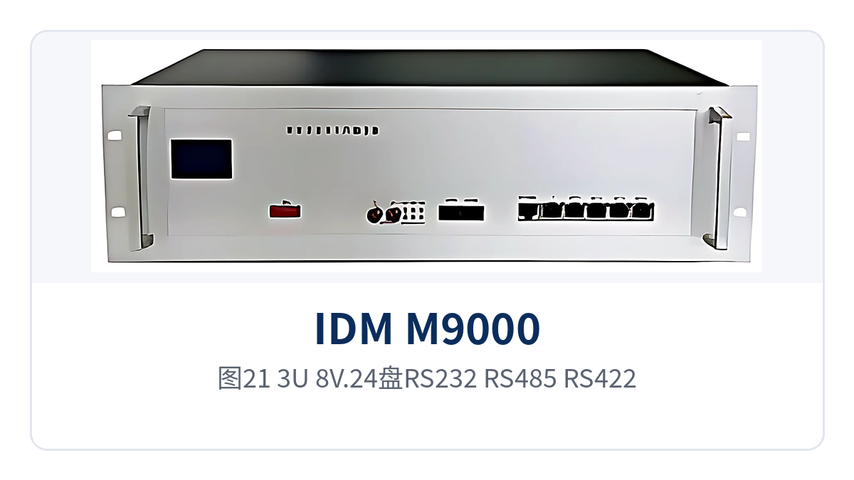
Figure 21: Close-up of the RS232/RS485/RS422 interface definitions on the 3U-8V.24 board
The significance of the two boards coexisting lies in framing services at once. Data, voice, and video are multiplexed within the same chassis and then travel over only one optical link, reducing the occupation of optical cable resources between sites, and O&M only needs to manage one network management view. For field sites with only one pair of optical fibers available, this multiplexing method directly determines whether the three service types can be enabled at the same time, and it is also a networking approach commonly adopted by Raytrans in military emergency communications vehicle solutions and government private network optical fiber communication solutions.
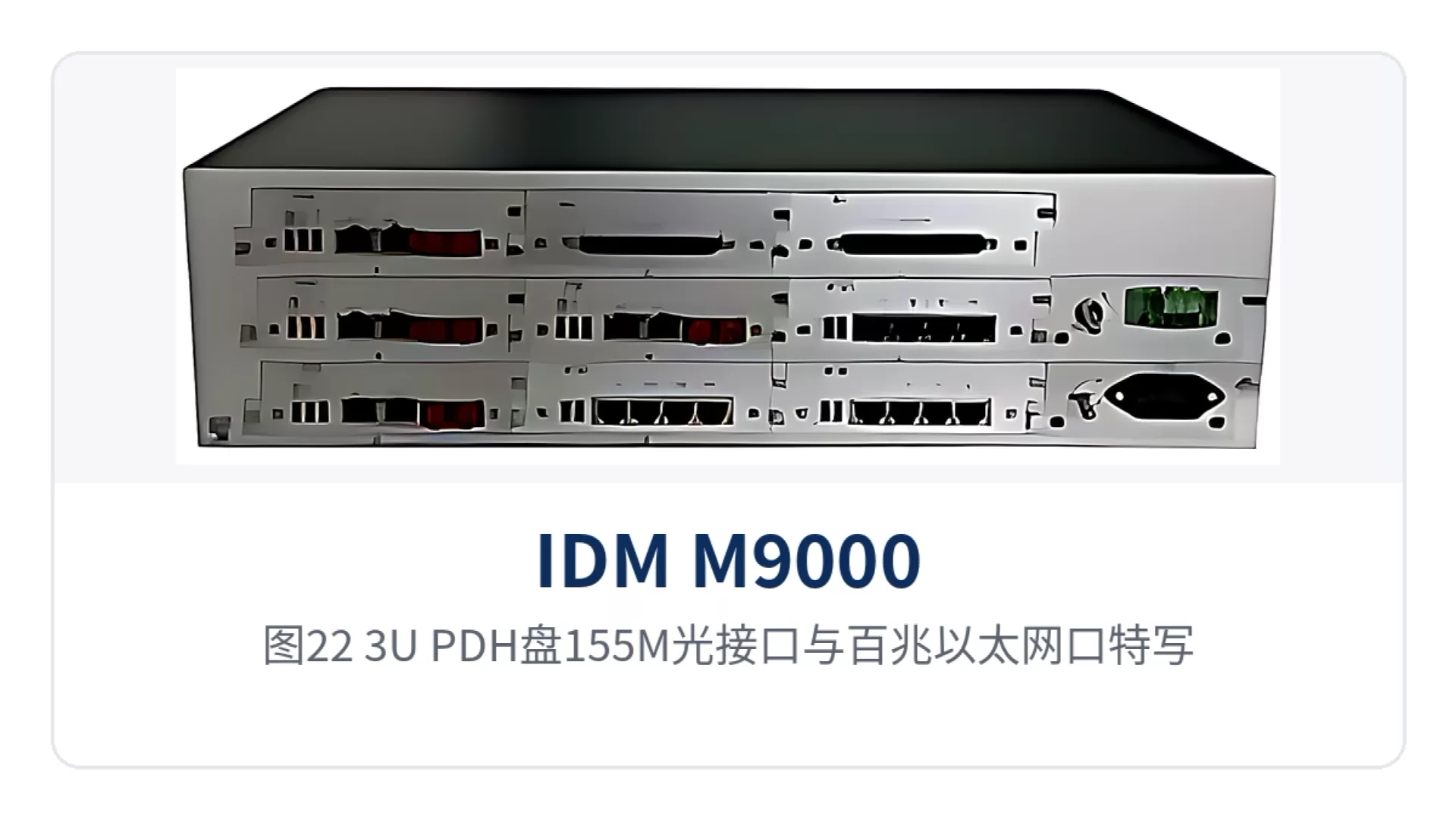
Figure 22: Close-up of the 155M optical interface and Fast Ethernet ports on the 3U-PDH board
The on-site wiring for serial port services is not complicated. Collection devices on the RS485 bus are connected in a daisy-chain manner, with a matching resistor added at the end; RS232 devices are wired point-to-point, with the shielding layer grounded at one end. After wiring is complete, confirm the receive/transmit status of each channel on the network management side, then proceed to service verification.
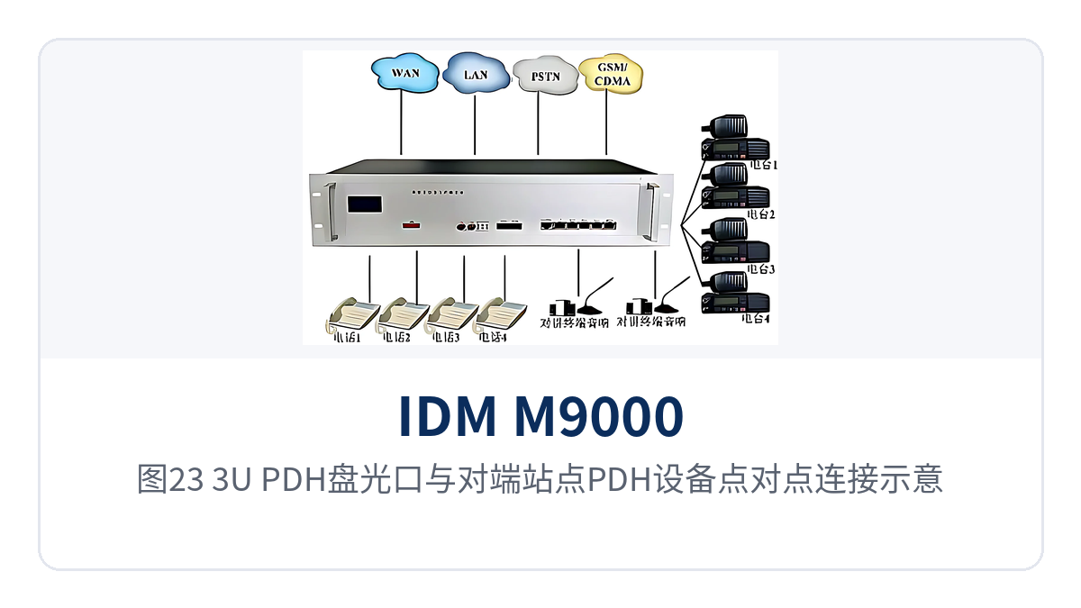
Figure 23: Point-to-point connection between the optical port of the 3U-PDH card and the PDH equipment at the opposite end site
How are magneto, hotline, and EM audio connected to an existing private network?
The 3U-8MVOICE card is an 8-channel multi-mode 2-wire audio plug-in card. Each channel can be configured through network management as an FXS, FXO, hotline, ordinary magneto, or 2100HZ magneto service card. The board mode is set by software, so the same card adapts to different sites, reducing the variety of spare parts and making access-side configuration for audio and video dispatching and converged communication more flexible.
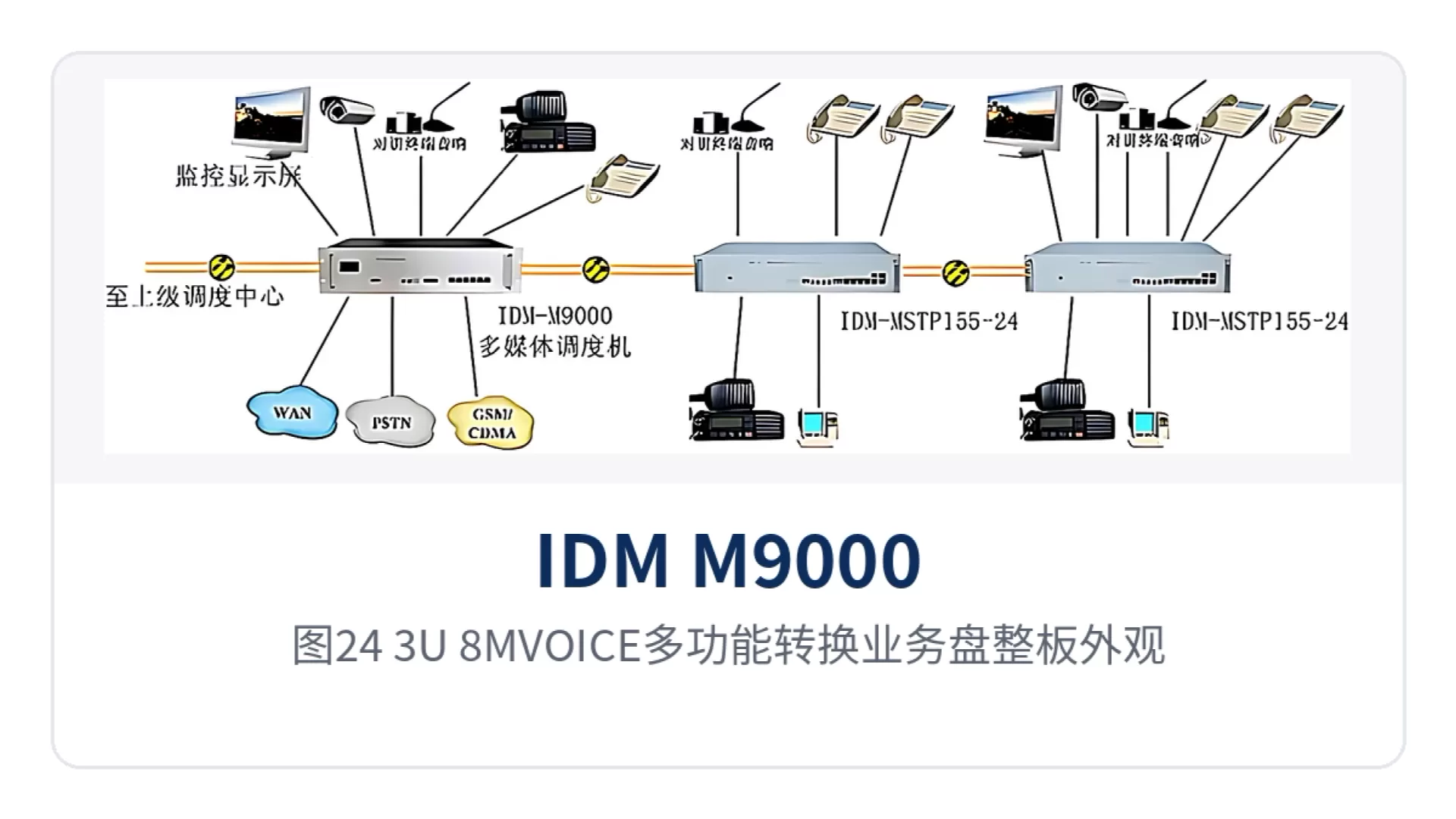
Figure 24: Board appearance of the 3U-8MVOICE multi-function conversion service card
For legacy systems requiring balanced audio, the 3U-4EM2/4VOX card provides 4-channel EM 2/4-wire audio with network-managed gain in steps of 0.5dB. The 3U-8SY64K card provides 8 codirectional 64K interfaces for interconnecting codirectional 64K services with existing PCM equipment, providing stable audio channels for converged dispatching.
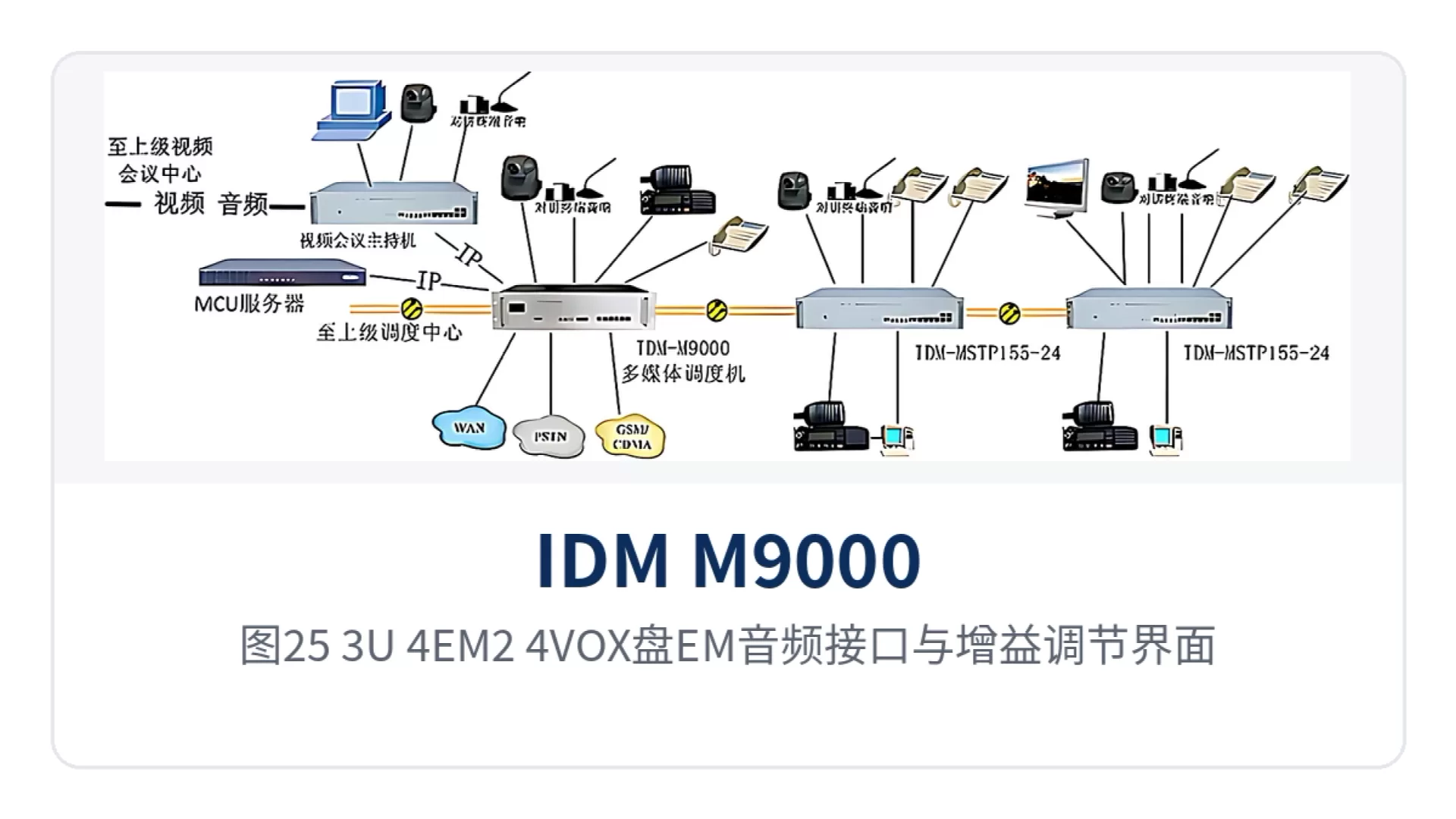
Figure 25: EM audio interfaces and gain adjustment interface of the 3U-4EM2/4VOX card
The 3U-8USER universal slots are used for expansion. The four universal slots can accommodate four dual-channel 64K service PCM plug-in cards. Sub-cards such as FXO, FXS, 2/4-wire audio, EM audio, ordinary magneto, V.24, 2100HZ carrier magneto, hotline telephone, and codirectional 64K can be mixed as required on site, meeting the interface combination requirements of a multimedia dispatching exchange in multiple scenarios.
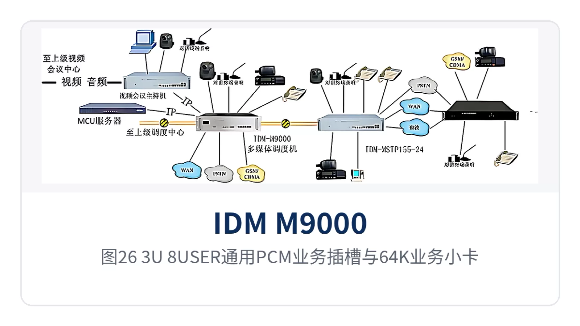
Figure 26: 3U-8USER universal PCM service slots and 64K service sub-cards
Universal slot sub-card configuration table
| Sub-card type | Capacity per card | Description |
|---|---|---|
| FXO card | 2 channels | Connects to interfaces such as automatic private branch exchange and common battery telephone exchange |
| FXS card | 2 channels | Connects to interfaces such as automatic private branch exchange and common battery telephone exchange |
| 2/4-wire audio card | 2 channels | Provides 2-wire or 4-wire pure audio access |
| EM 2/4-wire audio card | 1 channel | Provides 2-wire or 4-wire audio and EM signaling access; the EM interface operates at 48V and can be customized as required |
| Ordinary magneto card | 2 channels | Connects to magneto telephones or magneto exchanges; usually used in pairs at both ends |
| V.24 card | 2 channels | Provides 2-channel V.24 service access |
| 2100HZ carrier magneto card | 2 channels | Usually used in pairs; can also connect to the magneto trunk port of an exchange |
| Hotline telephone card | 2 channels | Provides point-to-point dedicated line telephone access with signaling tones such as remote ringback tone, on-hook tone, and howler tone |
| Codirectional 64K card | 2 channels | Provides 2-channel codirectional 64K services |
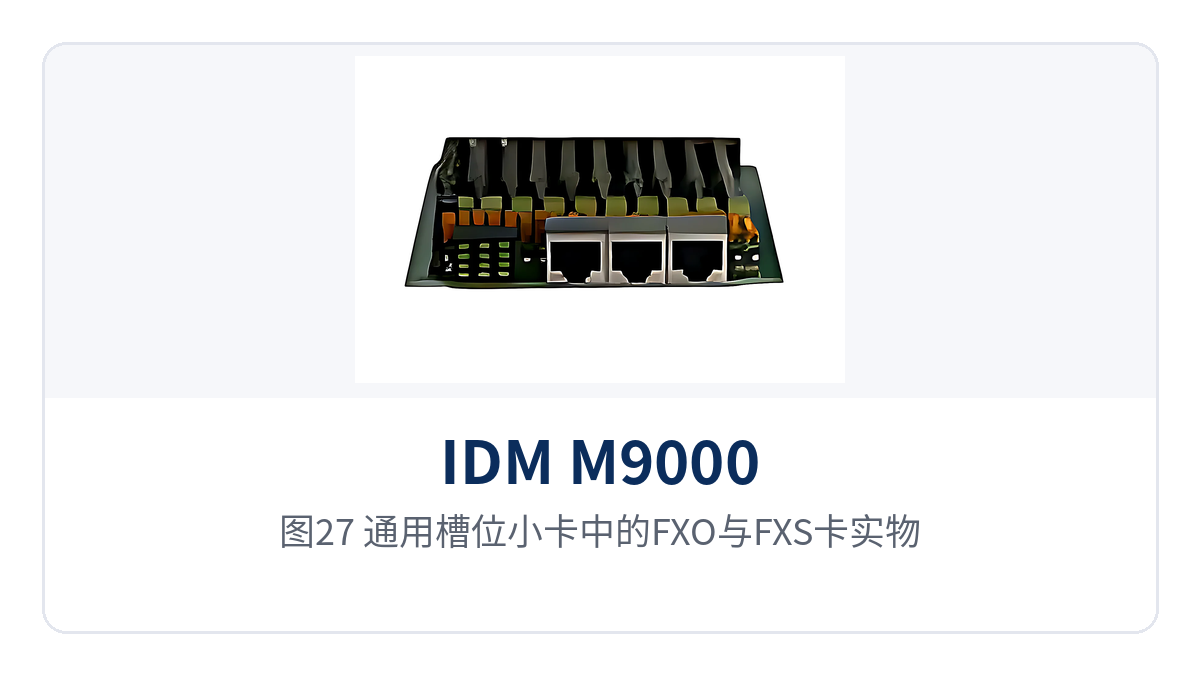
Figure 27: FXO and FXS cards among the universal slot sub-cards
The value of mixed sub-card insertion lies in purchasing by number of channels. When a site needs only 2-channel magneto and 2-channel hotline, inserting the corresponding sub-cards is sufficient; there is no need to purchase a whole card for a small number of interfaces. When interface requirements change, replace or add sub-cards while the chassis and common units remain unchanged. This on-demand expansion approach also makes it easy for command and dispatch system manufacturers to quickly adjust configurations on the project site.
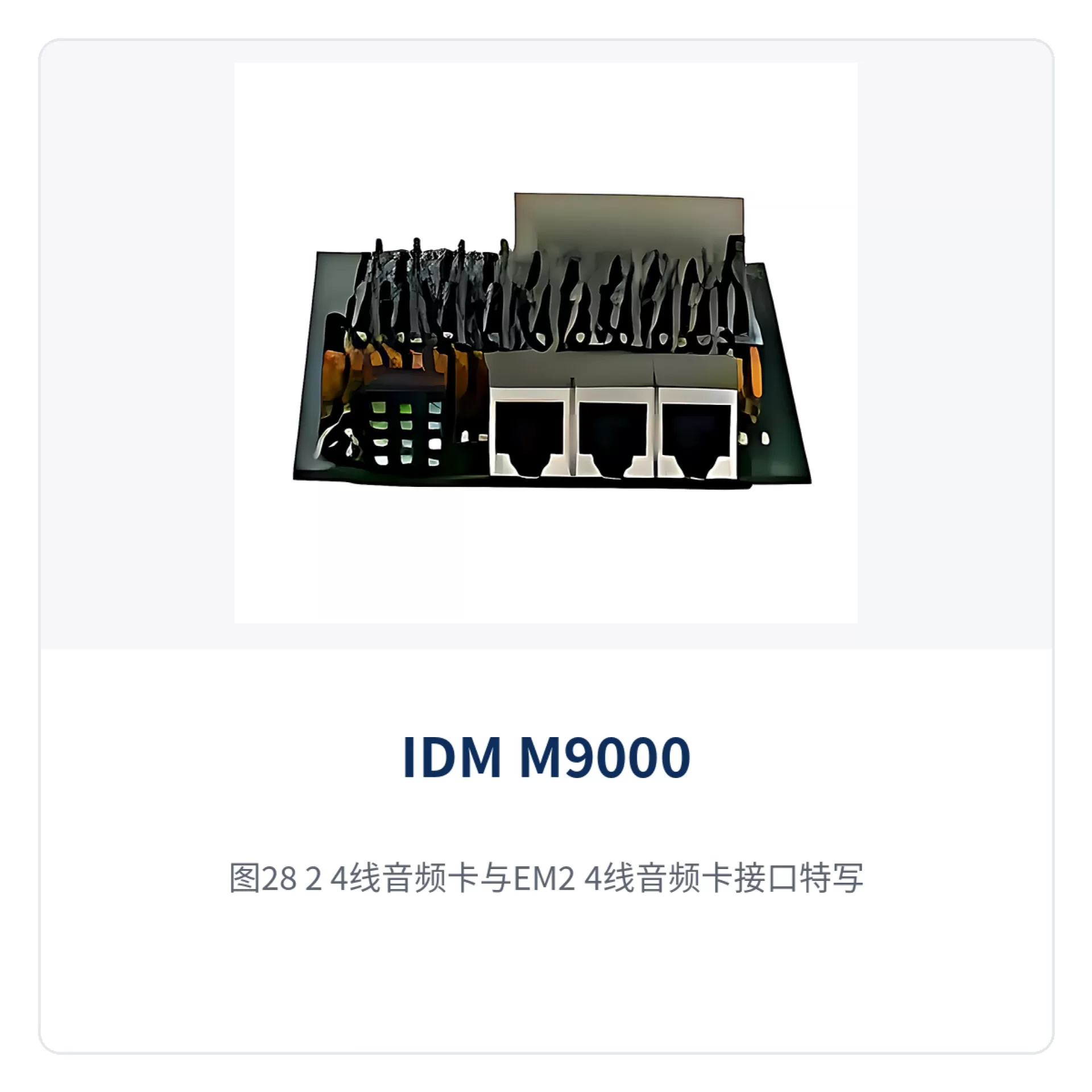
Figure 28: Close-up of the interfaces of the 2/4-wire audio card and the EM 2/4-wire audio card
Magneto and hotline services account for a high proportion of existing private networks. The ordinary magneto card connects to magneto telephones or magneto exchanges, while the 2100HZ carrier magneto card is used in pairs with the opposite end; the hotline telephone card connects to a preset opposite end as soon as it goes off-hook, making it suitable for positions such as sentry posts and duty rooms that need only one direct voice channel, and providing the most basic direct call assurance in command and dispatch scenarios.
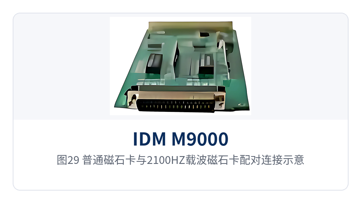
Figure 29: Paired connection between the ordinary magneto card and the 2100HZ carrier magneto card
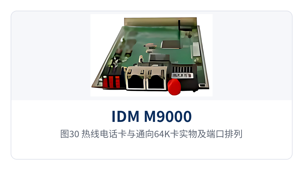
Figure 30: Appearance and port arrangement of the hotline telephone card and the codirectional 64K card
What sites is the portable multi-standard converged dispatching exchange suitable for?
The target sites for IDM M9000 are field sites with inconvenient transportation and unstable mains power and public networks. Emergency, electric power, and military users have different requirements for interface types, commissioning speed, and continuous operation. Configuring card by card according to the interface list is more site-appropriate than purchasing by model as a whole, and better leverages the networking advantages of the converged communication command and dispatch system.
Figure 31: Transport and deployment states of the IDM M9000 in a portable case
Emergency communications and civil air defense command: how to quickly form a network at an on-site command post
Emergency communications and civil air defense command are characterized by immediate use upon arrival. The IDM M9000 is transported to the site by vehicle or with the team, connects to on-site telephones and HF/VHF radio sets, and communicates with the rear command center through the 155M PDH optical port, with voice and on-site images backhauled simultaneously. For field emergency dispatching, whether the equipment can form a callable communication network within a short time after arrival is more important than the margin on the parameter table, which is also an indicator often prioritized in military emergency communications vehicle solutions.
Figure 32: Joint deployment of the IDM M9000 with radio sets and telephones in an emergency command vehicle
Civil air defense command posts and underground works often already have existing magneto telephones and dedicated line telephones. Using the 3U-8MVOICE card to configure these terminals in the corresponding modes for access means the existing cabling does not need to be removed; the upgrade is concentrated on the interfaces on the chassis side, and the operating habits of on-duty personnel do not need to change, minimizing the impact of the command and dispatch system upgrade on daily duty.
Figure 33: Deployment of the dispatching exchange and telephone terminals in the cabinet of a civil air defense command post
Electric power and oilfield field operations: how to exchange voice and data between sites
Field sites for electric power and oilfields are distributed between transmission corridors and well sites, and typically contain only dispatch telephones, a few channels of monitoring data, and a small amount of video. The IDM M9000 uses the 3U-8E1 service card to interconnect with existing transmission, the 3U-8V.24 card to access monitoring data, and the 3U-10FXS card to provide on-site telephone interfaces. One device covers all low-speed services at the site, and together with the dispatch console it enables unified management of on-site voice and data.
Figure 34: Interconnection between the dispatching exchange and E1 transmission equipment in the station building cabinet of a substation
When a site is unattended, voice and data are aggregated to the centralized control station over optical fiber, and on-duty personnel at the centralized control station can call on-site telephones and view serial port collection values. Field temperature differences and power supply fluctuations are real challenges for the equipment. The installation method of the chassis and boards is determined according to cabinet conditions, and the power supply format is confirmed with the manufacturer before ordering. In government private network optical fiber communication solutions, the power supply and installation conditions of such sites are usually also verified item by item.
Figure 35: Deployment of the dispatching exchange and monitoring terminals at an oilfield well site field site
Military and armed police private networks: how to incorporate terminals of different standards into the same dispatch
Terminals in military and armed police private networks come in many standards; HF radio sets, VHF radio sets, trunking intercom, magneto telephones, and IP phones may coexist. The IDM M9000 brings these terminals into the same dispatch network, so that a voice channel can be established between any two types of terminals, and cross-standard calls no longer rely on manual transfer. The converged dispatching capability is most directly demonstrated in cross-standard intercommunication.
Figure 36: Joint networking of HF radio sets and the dispatching exchange in a military field command post
Private networks have higher information security requirements than public networks. The equipment supports traditional PSTN interfaces as well as IP phones using the standard SIP protocol and the H.323 protocol. Voice is switched and transmitted entirely within the private network and, together with network encrypted transmission technology, services can be closed-loop without leaving the private network. The networking experience that Raytrans has accumulated in such private network projects can also serve as a reference for similar scenarios.
Figure 37: Access of the dispatching exchange to trunking radio sets and IP phones in an armed police private network cabinet
Figure 38: On-site deployment and cabling of the dispatching exchange and terminals of different standards under field conditions
In what order should on-site commissioning be carried out?
On-site commissioning proceeds in six steps, each with a verifiable completion marker. If the previous step is not confirmed before proceeding to the next, rework often occurs between wiring and configuration; the cost of repeated disassembly and assembly is higher than spending an extra ten minutes on verification, and proceeding in order also makes it easier to keep acceptance records.
Figure 39: Unpacking the IDM M9000 on arrival and checking the board list
- Check the enclosure and board list: verify the model and quantity of each board one by one against the ordering configuration, and confirm that the 3U-10FXS board, 3U-FXO board, 3U-8E1 service card, 3U-PDH board, 3U-8V.24 board, 3U-HDVcodec and others match the on-site interface requirements.
- Install the enclosure and connect grounding: install the enclosure into a 19-inch cabinet or portable case; after securing it, connect the protective ground first, then connect the power supply, and confirm that the front panel power indicator is normal.
- Connect subscriber-side terminals: connect telephones to the ports of the 3U-10FXS board and switch subscriber lines to the ports of the 3U-FXO board; for each connection, write the number and installation position on the label.
- Connect transmission-side links: select the 155M PDH optical port or E1 interface for uplink according to on-site conditions; connect optical fiber patch cords with receive/transmit crossover, and connect E1 coaxial cables with receive/transmit correspondence.
- Configure services and numbers: use the network management system to set the board service type, Gain Adjustment and video EOS bandwidth, plan extension numbers and outbound routing, and archive the configuration records.
- Perform dial-up verification item by item: test extension-to-extension calls, outbound calls through FXO, calls to the remote end through E1, video picture backhaul, and serial port data reporting one by one, and write the test results into the acceptance form.
Figure 40: On-site working status of connecting each channel according to the list and marking it with a label