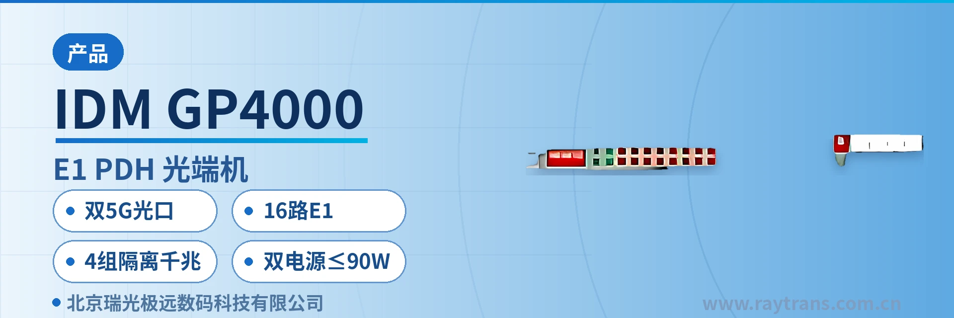
IDM GP4000-16E1 PDH Optical Multiplexer
16-channel E1, 4 groups of isolated gigabit over the same cable, one pair of optical fibers saves three or four devices
The IDM GP4000-16E1 PDH optical multiplexer provides 2 5Gbps SFP optical ports per standalone unit, supports up to 16 E1 interfaces, and can provide 4 groups of gigabit (1000M) physically isolated Ethernet ports; it offers an IP-based SNMP network management interface; supports DDM and ALS; provides an order-wire telephone; dual power supply; comprehensive alarm monitoring functions, high integration, low power consumption, stable performance and ease of use. It can be widely used in private networks such as public security, electric power, railway and mining, as well as public networks of China Mobile, China Unicom and China Telecom.
The IDM GP4000-16E1 PDH optical multiplexer is a 16-channel E1, four-group isolated gigabit optical multiplexer developed by Beijing Ruiguang Jiyuan Digital Technology Co., Ltd. It is a PDH optical multiplexer product for multi-service carrying scenarios, used to simultaneously transport 16 E1 leased lines and 4 groups of physically isolated gigabit Ethernet services over a single optical fiber. A standalone unit is equipped with 2 5Gbps SFP optical ports, 16 E1 interfaces and 4 groups of isolated gigabit ports, and provides IP-based SNMP network management, DDM digital diagnostics and an order-wire telephone, meeting the need in the product showcase to present the interface density and isolation capability of a multi-service optical multiplexer.
For site access in government private networks, electric power private networks and railway line communications, a single device completes same-cable backhaul of E1 channels and multiple isolated networks. The 16 E1 channels are transparently transported per ITU-T G.703, and the 4 gigabit port groups carry traffic separately by security domain, so service classification on the site side is already done at the interfaces and network boundaries no longer need to be drawn through switch configuration. As a gigabit network optical multiplexer, the device covers both E1 leased lines and isolated Ethernet services on the same platform, making it easy for an optical multiplexer manufacturer to standardize selection and deployment across government private network optical fiber communication solutions, smart mining communication solutions and military emergency communications vehicle solutions.
Key Specifications at a Glance: Dual 5G optical ports (2 5Gbps SFP) · 16 E1 channels (G.703/75 Ω/120 Ω/HDB3) · 4 groups of isolated gigabit Ethernet · Dual power supply ≤90 W · DDM and ALS · 20 Km, replaceable with long-distance optical modules
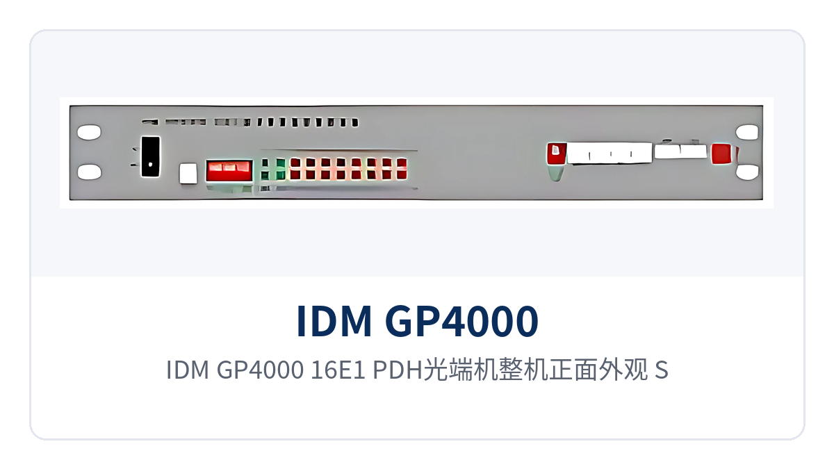
Figure 1: Front appearance of the IDM GP4000-16E1 PDH optical multiplexer, showing the layout of SFP optical ports, panel indicator LEDs and dual power supply units
What kind of device is a 16-channel E1 four-group isolated gigabit optical multiplexer
A 16-channel E1 four-group isolated gigabit optical multiplexer refers to a device form that provides 16 E1 channels and 4 groups of gigabit Ethernet ports within a single PDH multiplexer and multiplexes the two service types onto the same optical path for transmission. The E1 side transmits and receives at a rate of 2.048 Mbps with HDB3 line coding per ITU-T G.703, with a PCM30/32 frame structure and channel-associated signaling; after the signal enters the device, only multiplexing and demultiplexing are performed, and the original time slot content is not changed.
The 4 gigabit port groups on the Ethernet side each occupy an independent channel and forward independently inside the device; the ports do not share bandwidth or buffers, nor do they rely on VLAN partitioning to draw boundaries. The two service types each occupy their own channels on the optical path, the 64K time slots of E1 and the Ethernet packets do not crowd each other out, and service classification on the site side is completed by the interfaces themselves.
For a PDH site, this integration directly changes rack occupancy. The traditional approach is for a site to deploy one PDH optical multiplexer for E1 and one Ethernet optical multiplexer for each isolated network, with three to four devices each occupying an optical direction. The IDM GP4000-16E1 packs 16 E1 channels and 4 groups of isolated gigabit into one chassis, with a pair of optical fibers completing all backhaul, so rack space and optical cable cores are calculated on the basis of one device. For users focused on the product showcase and selection comparison, this product showcase approach of carrying multiple service types on one device also makes it easier for an optical multiplexer manufacturer to align the site list during solution discussions.
What services can one device carry
The capabilities of the IDM GP4000-16E1 PDH optical multiplexer revolve around four main lines: optical transmission, E1 access, isolated Ethernet and O&M, and a standalone unit constitutes a manageable PDH multi-service access node. The table below lists the capabilities item by item by function; during selection, simply check row by row against the site service list.
Function Overview
| Function | Description |
|---|---|
| Dual 5Gbps SFP optical ports | A standalone unit provides 2 5Gbps SFP optical interfaces; the optical modules are pluggable and selected by distance and fiber type |
| 16-channel E1 access | Provides 16 E1 channels with a bit rate of 2.048 Mbps and HDB3 line coding, compliant with ITU-T G.703, with selectable 75 Ω/120 Ω impedance |
| PCM30/32 frame structure | E1 is processed with the PCM30/32 frame structure and channel-associated signaling; transparent transport does not change the original time slot content |
| 4 groups of isolated gigabit | Provides 4 groups of 1000M Ethernet ports; each group occupies an independent channel inside the device, and services do not interfere with one another |
| Ethernet adaptive | RJ45 connector, 10M/100M/1000M adaptive, compliant with IEEE802.3, supporting full/half duplex/adaptive |
| IP SNMP network management | Provides an IP-based SNMP network management interface; device and link status can be viewed on the network management side |
| DDM digital diagnostics | Supports DDM digital diagnostics of optical modules, reading module parameters such as received and transmit optical power |
| ALS automatic laser shutdown | Supports the ALS function, automatically shutting down the laser when there is no light at the receive end, facilitating installation and maintenance |
| Order-wire telephone | Built-in order-wire telephone channel, allowing on-site voice contact between the two ends during commissioning and maintenance |
| Dual power supply | AC220V and DC-48V power supply, suitable for AC equipment rooms and communications DC equipment rooms |
| Alarm monitoring | Provides alarm monitoring; panel indication and network management reporting jointly reflect device and link status |
| Low power consumption operation | Overall power consumption of the unit does not exceed 90 W, keeping heat dissipation and power supply capacity pressure in long-term operation equipment rooms controllable |
Key Specifications
The specifications are listed in three parts: optical interfaces, E1 interfaces, and Ethernet and power supply environment. The values are taken from the original product documentation. For engineering calculations, take the values from the table; the optical power budget and site power supply capacity are both based on the specifications in the table to avoid re-issuing orders. For items marked as typical values or standard configuration in the table, confirm the specific modules and formats with commercial confirmation when ordering.
Optical Interface and E1 Interface Parameters
| Parameter/Specification | Specification/Indicator | Description/Applicable Conditions |
|---|---|---|
| Optical interface type | SFP | Pluggable module, selected by distance and fiber type |
| Fiber mode | Single-mode (multimode optional) | Single-mode for medium and long distances, multimode for short distances within a station |
| Receive/transmit rate | 2.5G/5.25G | Corresponds to the rate level of the SFP optical module fitted |
| Receive/transmit wavelength | 1310nm/1550nm | Determined by the selected optical module; the two ends must match as a pair |
| Transmit optical power | +2dBm | Typical specification on the transmit side of the optical module |
| Receiver sensitivity | Better than -20dBm | Typical specification on the receive side; the link margin is calculated on this basis |
| Transmission distance | 20Km | Standard configuration; long-distance optical modules can be added to extend transmission |
| Number of E1 channels | 16 | A standalone unit can connect 16 E1 services |
| E1 bit rate | 2.048Mbps | Rate of a single E1 channel |
| E1 line coding | HDB3 | Compliant with ITU-T G.703 |
| E1 impedance | 75 Ω/120 Ω | 75 Ω unbalanced coaxial and 120 Ω balanced interfaces are selected according to the peer device |
| E1 frame structure | PCM30/32 | Channel-associated signaling, transparent transport mode |
Ethernet, Power Supply and Environmental Parameters
| Parameter/Specification | Specification/Indicator | Description/Applicable Conditions |
|---|---|---|
| Ethernet interface | RJ45, 10M/100M/1000M adaptive | Compliant with IEEE802.3, full/half duplex/adaptive |
| Number of isolated gigabit port groups | 4 groups | Each group has an independent channel and is connected separately by security domain |
| Network management interface | IP-based SNMP | Centralized viewing of device status on the network management side |
| Power supply mode | AC220V/DC-48V | The two power supplies are connected separately and selected according to equipment room conditions |
| Overall power consumption | ≤90 W | Unit-level value including service interfaces and optical modules |
| Operating temperature | -10℃~+50℃ | Equipment room and non-temperature-controlled site cabinet environments |
| Relative humidity | 0~95% (non-condensing) | Indoor installation conditions |
| Dimensions | 482×309×132 (mm) | 19-inch standard chassis, front-mounted in the cabinet for maintenance |
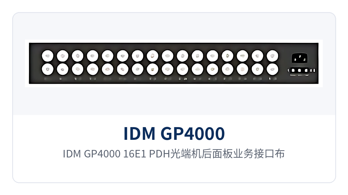
Figure 2: Rear panel service interface layout of the IDM GP4000-16E1 PDH optical multiplexer, with 16 E1 coaxial interfaces and 4 groups of isolated gigabit RJ45 interfaces
How to calculate the dual 5G SFP optical ports and the optical link
Dual 5G optical ports means a standalone unit is equipped with 2 SFP optical interfaces at 5Gbps rate; the optical modules are pluggable, so a faulty module can be replaced without returning the whole unit for repair. Single-mode is the standard configuration for fiber mode, and multimode modules can be selected for short-distance cabling within a station; the receive/transmit wavelengths are 1310nm/1550nm, and the optical modules at both ends must match as a pair by wavelength.
Whether the link works is calculated based on transmit optical power and receiver sensitivity, not just the nominal distance. With transmit optical power of +2dBm and receiver sensitivity better than -20dBm, the difference between the two constitutes the available loss budget; after deducting splice point, adapter and per-kilometer optical cable attenuation, the remaining margin is the engineering lifetime space of this link. The standard configuration is designed for 20Km transmission; when the site distance exceeds this, long-distance optical modules are added to extend it, with modules at both ends replaced as a pair.
The status of the optical modules can be read on the network management side, relying on the DDM digital diagnostics function. Deterioration trends such as received optical power declining over the years and abnormal module temperature can be identified from the module parameters before service interruption, and maintenance is scheduled within a planned window. ALS protects on-site personnel during installation and maintenance: the laser automatically shuts down when there is no light at the receive end, preventing laser exposure when working facing the fiber end face.
As a dual 5G optical port PDH optical multiplexer, the optical ports of the IDM GP4000-16E1 are more than a rate specification; they also determine how many E1 channels and how many isolated networks this link can carry. The line rate of the 16 E1 channels totals about 32.768Mbit/s, and the 4 gigabit groups forward at line rate, with the two service types carried in parallel over the 5G optical path. At sites where multi-service optical multiplexers and gigabit network optical multiplexers coexist, this type of PDH optical multiplexer is often used by Raytrans in scenarios such as government private network optical fiber communication solutions, smart mining communication solutions and military emergency communications vehicle solutions, and intrinsically safe mining communication occasions can also be fitted with the corresponding format as required.
How to divide networks with 4 groups of isolated gigabit Ethernet
4 groups of isolated gigabit means the 4 groups of gigabit Ethernet ports each occupy an independent channel and forward independently inside the device; the ports do not share bandwidth or buffers, and a traffic burst on one port will not consume the forwarding capability of another. Physical isolation is completed at the hardware channel level, the two networks are invisible to each other, and the security zone boundary is drawn by the ports themselves. For a PDH optical multiplexer undertaking the product showcase and multi-service access, this port-level isolation is a common design approach in government private network optical fiber communication solutions.
On site, services are assigned to the 4 port groups by security domain; after wiring, no inter-port access control is needed, nor is reliance on the access control list of a switch. The assignment follows the site's network plan: first determine which networks exist and what security level each has, then map them down to ports. A common division of labor is as follows:
- Video surveillance occupies one group exclusively, so camera streams do not mix with office traffic;
- Dispatch data or production control services occupy one group, separate from video and office networks;
- Office and O&M networks are combined into one group, so port maintenance affects only that service;
- One spare group is reserved in the cabinet, so new services can be connected directly later without re-laying optical cables.
The direct benefit of isolation is a clear fault boundary. An equipment or traffic anomaly on one port will not slow down forwarding on the other three, nor will it create lateral access paths between network segments. For private network access points that carry both production and management networks and require that a fault on one network not spill over, port-based boundaries are easier to pass network-related reviews than logical partitioning, which is one reason multi-service optical multiplexers are favored in government private network optical fiber communication solutions.
All 4 port groups support 10M/100M/1000M adaptive and full/half duplex/adaptive; when connecting to existing switches, the rate is negotiated as before, with no configuration change needed on the device side. The number of gigabit ports is determined by the site's current services; leave the wiring position for the reserved group ready in the cabinet, and only add patch cords during capacity expansion.
How to connect 16 E1 channels to the existing network
The 16 E1 channels are connected according to ITU-T G.703, with a bit rate of 2.048 Mbps and HDB3 line coding, PCM30/32 frame structure, and channel-associated signaling (CAS). Once inside the unit, the signals are only multiplexed and demultiplexed, and the E1 restored at the opposite end remains consistent with what entered. Transparent transmission means existing equipment needs no configuration changes: dispatch automation devices, relay protection equipment, and PCM equipment keep working with their original E1 parameters, and no time-slot remapping is required between the two ends.
Check the impedance before wiring. 75 Ω is an unbalanced coaxial interface, using coaxial cable and BNC connectors; 120 Ω is a balanced interface, using twisted pair and the corresponding terminals. The impedance of the equipment at both ends must match; mixed connections cause return loss and bit errors. Connect the receive and transmit directions pair by pair according to the labels at the opposite end, and route E1 cables separately from optical cables, away from high-voltage and variable-frequency equipment.
During commissioning, check the following items in order, and confirm each item both visually and by reading before moving to the next, so that a configuration problem in an earlier stage is not carried into live service. Schedule the checks during idle hours, record the results item by item, and when an anomaly is found, first determine the fault direction between the local end and the opposite end:
- Check the E1 alarm indication channel by channel, and confirm that the receive, transmit, and frame alignment of the 16 channels are normal;
- Check the CAS status, and confirm that the voice channel signaling is consistent with the opposite end;
- After live service is connected, recheck bit errors and alarms to confirm that the cutover has not introduced new anomalies;
- Check the device and link status on the network management side, and register the site information in the records.
PCM equipment still running on the existing network can be retained as is; the E1 channels are simply passed through transparently, and narrowband voice channels do not need to be reconfigured one by one. During the cutover window, bring up one channel first for verification, then release the remaining channels in batches; if an anomaly occurs, the troubleshooting scope is confined to a single channel.
Typical Application Scenarios
The IDM GP4000-16E1 PDH optical multiplexer is mainly deployed point to point: one unit at the service site and one in the central equipment room, with the two ends directly connected over optical fiber. The E1 channels and isolated gigabit links are restored at the central side and connected back to the existing transmission and switching equipment; site expansion only adds interfaces, with no need to lay new optical cables. Typical uses in three industries are as follows.
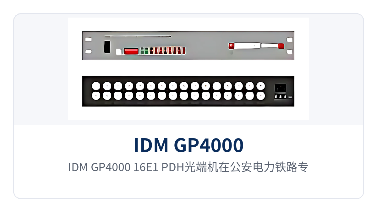
Figure 3: Point-to-point networking schematic of the IDM GP4000-16E1 PDH optical multiplexer in public security, electric power, and railway private networks, with E1 and isolated gigabit services connected at one end and backhauled to the central equipment room at the other
Public Security Network: E1 Leased Lines and Surveillance Network Backhauled over the Same Cable Between Police Stations and Branch Bureaus
Police stations, checkpoints, and branch bureaus need to carry Public Security Network data, video surveillance images, and E1 trunks of SPC exchanges, while sites are distributed and fiber cores are scarce. The IDM GP4000-16E1 provides 16 E1 channels and 4 groups of isolated gigabit links in one enclosure: E1 trunks run over E1 channels, while video surveillance and the Public Security Network each occupy one isolated gigabit port.
The video network and the service network are separated on hardware channels, so an anomaly on one group of ports does not spill over to another, and the boundary is clear during network security inspections. Dual AC220V and DC-48V power supplies cover both the AC mains power at police stations and the DC communications power in equipment rooms; overall power consumption is no more than 90 W, leaving sufficient power and heat dissipation margin for small cabinets.
Electric Power Private Network: Isolated Backhaul of Telecontrol E1 and the Production Network at Substations
Substations, distribution stations, and new energy stations run dispatch automation, relay protection signals, and video surveillance at the same time; most sites are unattended and equipment room space is limited. The IDM GP4000-16E1 brings the E1 channels for telecontrol and protection information, the production control network, and the video surveillance network into one device, so each site no longer needs a separate optical multiplexer for each type of service.
The production control network exclusively occupies one isolated gigabit port and is carried separately from the office and video networks; on the E1 side, G.703 transparent transmission is used, and the existing channel parameters of the dispatch master station at the opposite end remain unchanged. DDM and SNMP network management let O&M personnel check the optical module receive power and device status of remote stations at the centralized control station, so inspection of unattended sites no longer requires a trip to the site every time.
Railway Line Communication: E1 Channels and Office Network Access Between Section Stations and Stations
Between stations along a railway and section equipment rooms, train dispatching telephone, signaling system E1 channels, and office network data need to be carried, while station spacing is several kilometers and equipment room conditions are limited. The IDM GP4000-16E1 is deployed point by point according to site distribution; each station connects services nearby and backhauls them to the station or communication center over trunk optical fiber.
The 16 E1 channels match the multiple 2M channels of the signaling and communication disciplines, and the 4 groups of isolated gigabit links divide surveillance, office, and O&M into different networks, so inspection of one channel does not affect the others. The standard 20Km transmission covers common section distances, and longer sections are handled by adding long-distance optical modules.
Conclusion
As a 16-channel E1 optical multiplexer with four groups of isolated gigabit links, the IDM GP4000-16E1 uses two 5Gbps SFP optical ports to carry 16 E1 channels and 4 groups of physically isolated gigabit Ethernet, and comes with DDM, ALS, SNMP network management, service function telephone, and dual power supplies; overall power consumption is no more than 90 W and the operating temperature is -10℃~+50℃. One device replaces multiple PDH optical multiplexers, so rack space, optical cable cores, and the variety of spare parts are all counted as one unit. Raytrans also presents this model as the mainstay of multi-service access in its optical multiplexer product showcase.
During selection, first count the number of E1 channels and Ethernet security domains at the site, then determine the optical module distance grade according to the link loss budget, and check the power supply format and cabinet space. The IDM GP4000-16E1 PDH optical multiplexer targets site access in public security private networks, electric power private networks, and railway line communication; once the equipment at both ends is configured as a pair, services can be enabled.