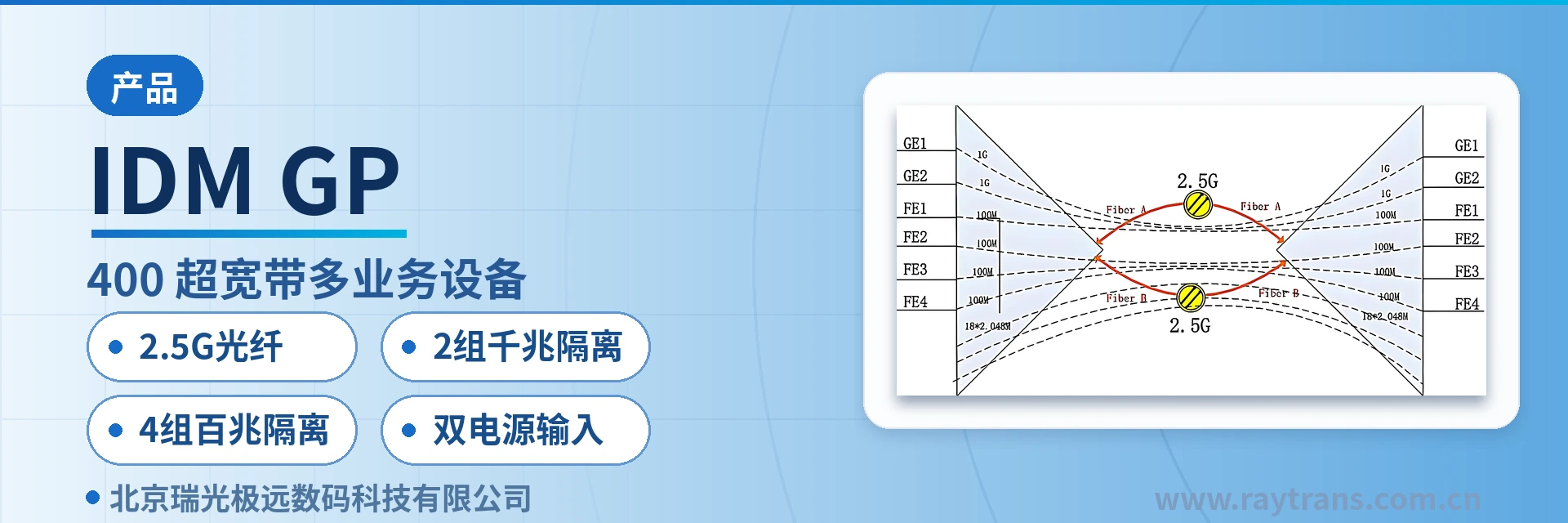
IDM GP-2400 Ultra-Broadband Multi-Service Device
Six groups of physically isolated Ethernet over a single 2.5G fiber core, dual optical ports with 1+1 hot standby
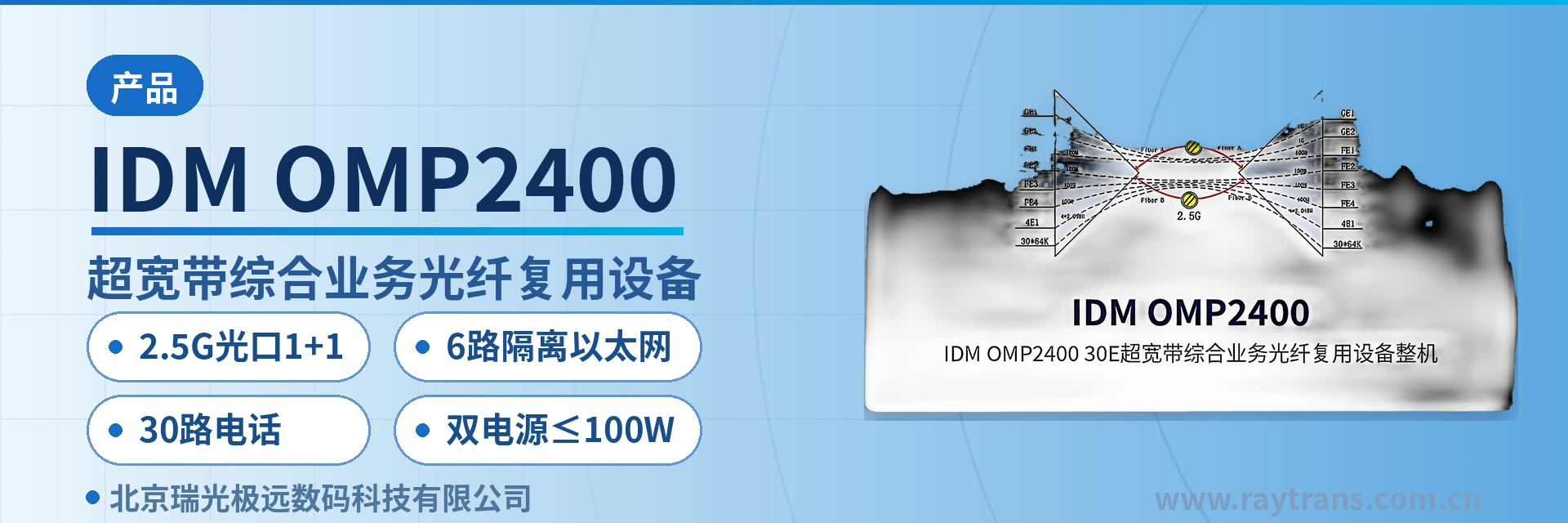
The IDM GP-2400 ultra-broadband multi-service device can transmit two groups of physically isolated wire-speed gigabit Ethernet and four groups of wire-speed physically isolated 100M Ethernet over 2.5G optical fibers. It provides two groups of 2.5G optical fiber hot standby. It can provide both ~220V and -48V power supplies.
The IDM GP-2400 ultra-broadband multi-service device is a PDH optical multiplexing device developed by Beijing Ruiguang Jiyuan Digital Technology Co., Ltd. (Raytrans). As one of the representative products of a professional optical multiplexer manufacturer and SDH equipment manufacturer, the device carries two physically isolated wire-speed gigabit Ethernet channels and four wire-speed physically isolated 100M Ethernet channels simultaneously over a pair of 2.5G optical fibers, meeting the multi-service carrying requirements of government private network optical fiber communication solutions and military emergency communications vehicle solutions. The unit is a standard 19-inch 1U chassis; the two SFP optical ports can form a hot standby pair, and the six Ethernet services at the site side each use an independent channel with no bandwidth contention, fully reflecting the physically isolated multi-service design highlighted in the product showcase.
Key specifications at a glance: 2× SFP 2.5G optical ports (1310/1490/1550nm optional) · 2 physically isolated wire-speed gigabit channels · 4 physically isolated wire-speed 100M channels · 1+1 hot standby over dual optical ports · AC220V/DC-48V dual power supply · overall power consumption ≤15W
What kind of device is the ultra-broadband multi-service device
In the name IDM GP-2400 ultra-broadband multi-service device, "ultra-broadband" refers to the 2.5Gbps optical port rate, and "multi-service" means six mutually isolated Ethernet channels carried in parallel over the same optical path. The devices are deployed as a pair at both ends: one end multiplexes the six Ethernet services onto the optical path, and the other end restores them on the original interfaces, without changing the frame structure or addresses of the services in the transmission path. As a professional optical multiplexer manufacturer, Raytrans positions this product line in its product showcase as a multi-service access platform for private networks.
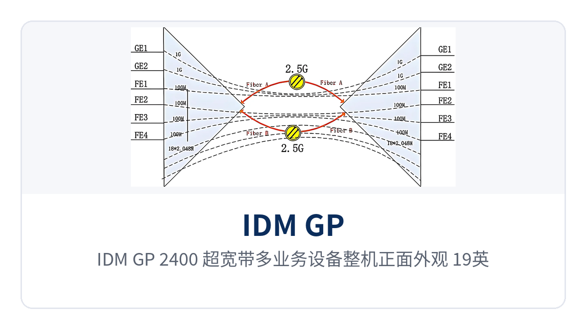
Figure 1: Front view of the IDM GP-2400 ultra-broadband multi-service device, 19-inch 1U chassis with front-panel run and alarm indicator LEDs
The physical isolation of the six Ethernet channels is implemented inside the device: each interface has its own encapsulation and forwarding channel, and each channel exclusively owns its bandwidth without relying on VLAN partitioning. When a broadcast storm, loop, or port failure occurs on one channel, the bandwidth and latency of the other channels are unaffected — this is the key difference between physical isolation and logical isolation in private network scenarios.
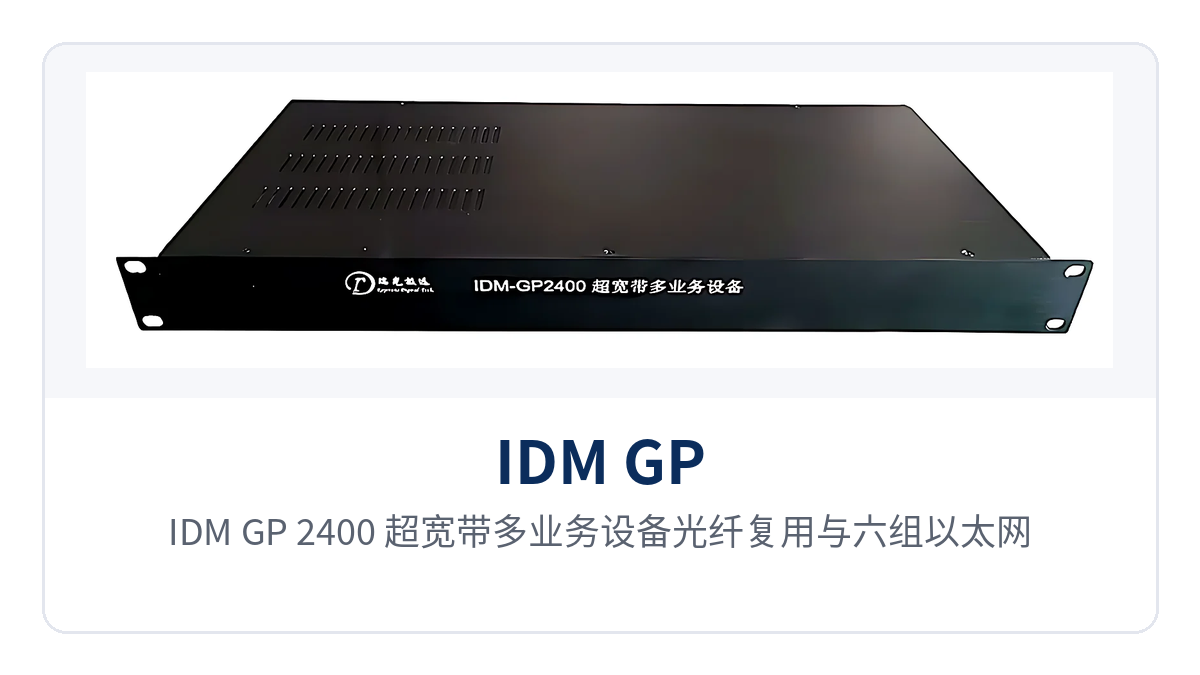
Figure 2: Block diagram of optical fiber multiplexing and physical isolation of six Ethernet channels in the IDM GP-2400 ultra-broadband multi-service device
Which services can one device carry simultaneously
The IDM GP-2400 ultra-broadband multi-service device integrates optical fiber transmission, two isolated gigabit channels, four isolated 100M channels, and dual power inputs into a single 1U unit, replacing the multiple optical-to-electrical converters previously deployed separately for each network zone. The capabilities and corresponding interface standards are listed in the table below, and the configuration list and bid specifications can be cited directly.
| Function | Description |
|---|---|
| 2.5G optical fiber transmission | SFP optical ports at 2.5Gbps, single-mode (multi-mode optional), wavelength 1310/1490/1550nm optional; one optical fiber carries six Ethernet services simultaneously |
| 2 isolated gigabit channels | Two physically isolated wire-speed 1000M Ethernet ports, each with exclusive 1000M bandwidth, compliant with IEEE802.3 |
| 4 isolated 100M channels | Four wire-speed physically isolated 100M Ethernet ports with independent encapsulation and forwarding, connectable to office, surveillance, conference, and dispatch networks respectively |
| Dual optical port hot standby | Two 2.5Gbps SFP optical ports can form 1+1 protection; when the primary optical path suffers a fiber break or received optical power degradation, services switch to the backup optical path |
| Dual power input | Supports both AC220V and DC-48V power supply modes, with optional dual power supply configuration, the two inputs drawn from different distribution circuits |
| Centralized networking | Supports point-to-point, chain, and centralized point-to-multipoint networking, and can also form hybrid networking with the IDM OMP integrated service platform and MSAP-G3CP aggregation-type equipment |
| Low power consumption and wide temperature operation | Overall power consumption ≤15W, operating temperature -20℃ |
Key specifications
The specifications are divided into three parts: optical interfaces, Ethernet interfaces, and power supply and environment. The values in the table below are taken from product documentation; parameters without specified test conditions are understood under normal-temperature, normal-humidity equipment room environment. During project calculation, verify each item against the actual configuration; the distance grade of the selected optical module determines the usable link length.
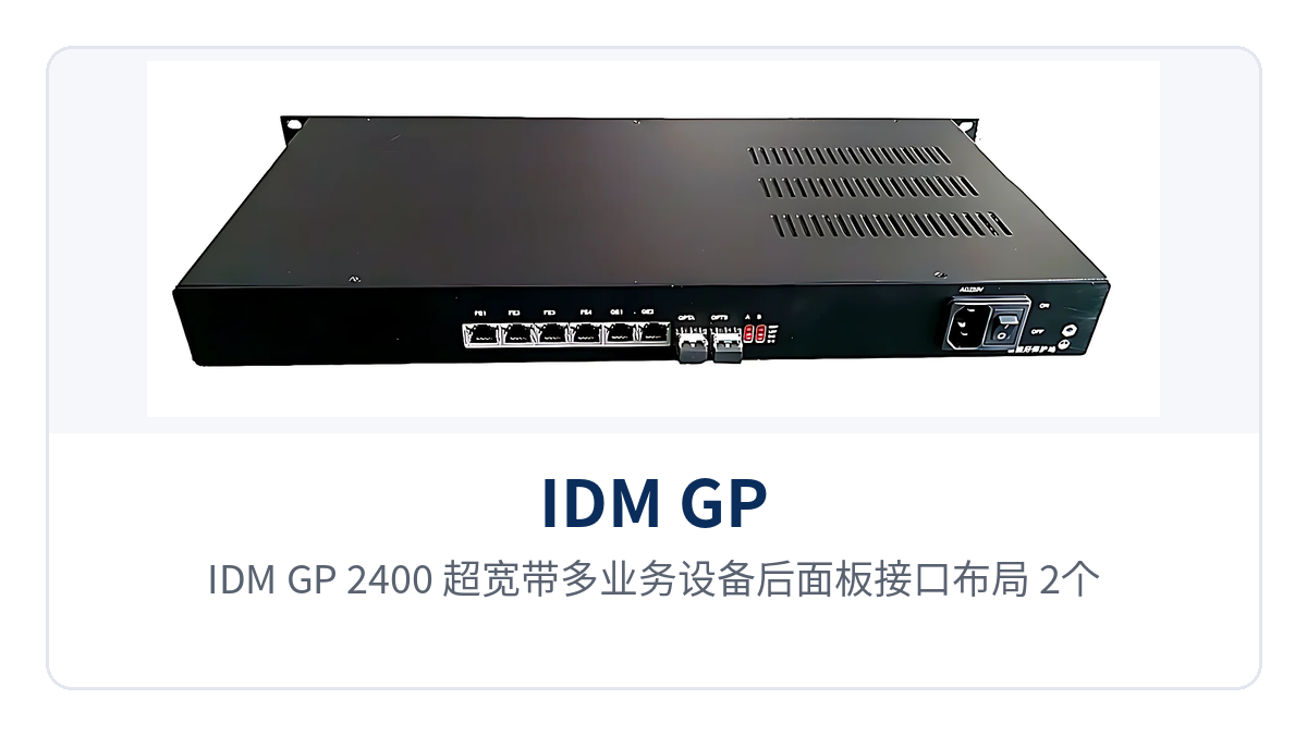
Figure 3: Rear panel interface layout of the IDM GP-2400 ultra-broadband multi-service device, with 2 SFP optical ports, 2 gigabit and 4 100M RJ45 ports, and dual power supply terminals
| Item | Parameter/Specification | Description/Applicable Conditions |
|---|---|---|
| Optical interface type | SFP | Pluggable module, replaceable by distance and wavelength |
| Fiber mode | Single-mode (multi-mode optional) | Selected according to line distance and fiber core conditions |
| Optical port rate | 2.5Gbps | The six Ethernet services share the bandwidth of this optical path |
| Number of optical ports | 2 | Can form 1+1 hot standby |
| Wavelength | 1310/1490/1550nm | Used in pairs at both ends; wavelengths at both ends of the same link must match |
| Transmit optical power | -1~-10dB | Subject to the measured value of an optical power meter |
| Receiver sensitivity | Better than -24dBm | The link loss budget can be calculated on this basis |
| Transmission distance | 20km/40km/80km | Determined by the distance grade of the selected SFP module |
| Ethernet interfaces | 6 groups of RJ45 | 2 wire-speed gigabit + 4 wire-speed 100M, physically isolated |
| Transmission rate | 10M/100M/1000M | Compliant with IEEE802.3, full/half duplex/adaptive |
| Power supply mode | DC-48V/AC220V | Optional dual power supply |
| Overall power consumption | ≤15W | Unit value including optical modules |
| Operating temperature | -20℃~+50℃ | Equipment room, cabinet, and wide-temperature site environments |
| Relative humidity | 0~95% (non-condensing) | Upper limit of relative humidity |
Whether a link remains stable over the long term depends on the loss budget, not just the nominal rate. With transmit optical power of -1~-10dB and receiver sensitivity better than -24dBm, the margin left between the two ends must cover optical cable attenuation, splice points, and patch cord loss. On site, first measure the received optical power with an optical power meter, then compare it with the -24dBm threshold and leave a margin; if it is close to the threshold, first clean the fiber adapter and patch cord end faces, and if it is still insufficient, switch to a module with a higher power budget according to the distance grade.
How 2.5G optical fiber hot standby and physical isolation keep private networks uninterrupted
The two 2.5G optical ports can be configured as 1+1 hot standby: the primary optical path carries all six Ethernet services, while the backup optical path stands by synchronously. When the primary link suffers a fiber break, optical module failure, or received optical power degradation below the threshold, services automatically switch to the backup optical path, and data between sites does not stop due to a single point of failure. This mechanism is particularly important in government private network optical fiber communication solutions and military emergency communications vehicle solutions, and Raytrans can provide supporting selection based on its PDH and SDH equipment manufacturer product lines for such scenarios.
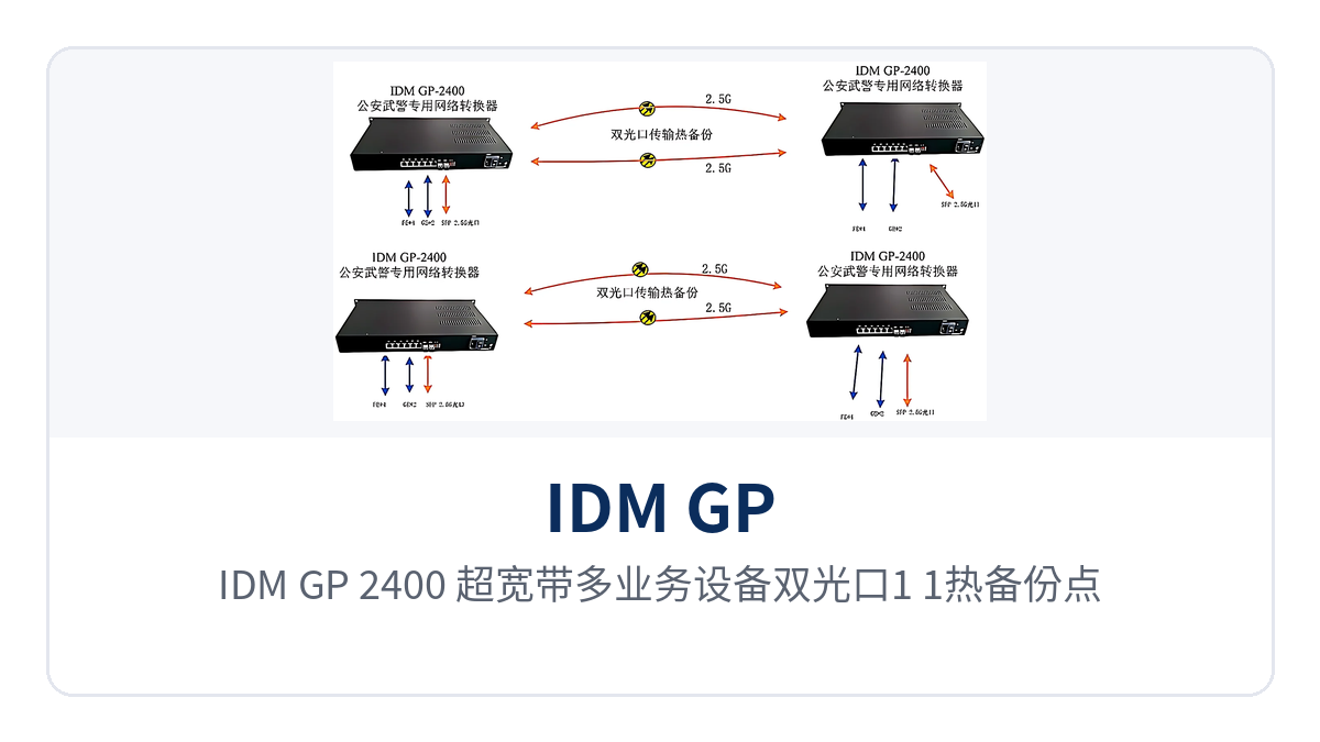
Figure 4: Point-to-point networking diagram of 1+1 hot standby over dual optical ports in the IDM GP-2400 ultra-broadband multi-service device, with both ends interconnected via two 2.5G single-mode fibers
The switching effect must be verified during commissioning: first confirm that the two optical fibers run along different routes and terminate at different terminals, avoiding simultaneous interruption of both paths by construction in the same conduit; then disconnect the primary fiber and observe whether the gigabit and 100M channels continue forwarding and whether the service side sees packet loss or sudden latency changes. After verification, record the fiber numbering, wavelengths, power supply circuits, and interface assignments in the as-built documentation, so that capacity expansion can proceed according to the drawings.
Typical application scenarios
The IDM GP-2400 ultra-broadband multi-service device is mainly deployed point-to-point, and can also aggregate sites along a line in chain or centralized point-to-multipoint mode, with the central side forming hybrid networking with the IDM OMP integrated service platform and MSAP-G3CP aggregation-type equipment. The network zoning of electric power, rail transit, and military and armed police private networks differs, and the allocation of the six isolated channels also varies; the independent encapsulation structure of each interface group can be seen directly in the product showcase.
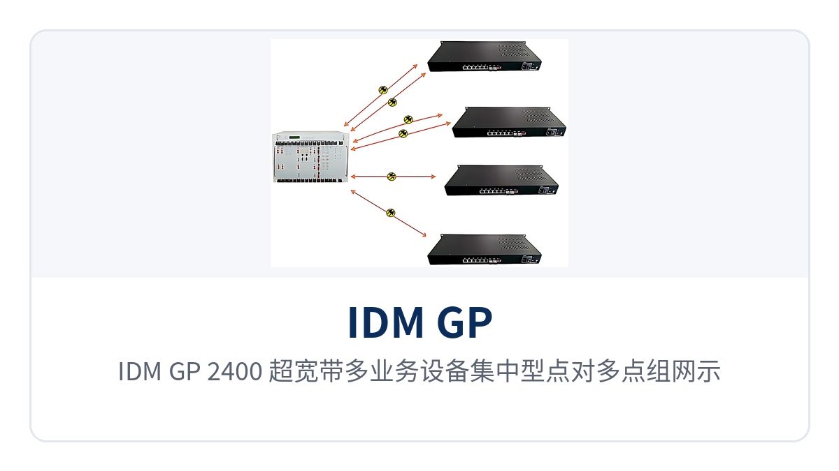
Figure 5: Centralized point-to-multipoint networking diagram of the IDM GP-2400 ultra-broadband multi-service device, with multiple remote stations aggregated to the central platform via 2.5G optical fibers
Electric power private network: separate network carrying of substation production data and video surveillance
Between substations and dispatch stations, production control data, video surveillance, office networks, and dispatch voice channels usually run simultaneously. The IDM GP-2400 ultra-broadband multi-service device is installed at each station, using one 2.5G single-mode fiber to multiplex and backhaul the six Ethernet services: production control and integrated data use two isolated gigabit ports, while surveillance and office use 100M ports, with boundaries drawn by interface, so there is no need to configure VLANs one by one on switches. As a PDH and SDH equipment manufacturer focused on government private network optical fiber communication solutions, Raytrans configures interface combinations flexibly according to site conditions in this scenario.
On the power supply side, AC220V or DC-48V can be selected according to site conditions, and the -48V DC power commonly available in communications equipment rooms can be connected directly; when the dual power supply configuration is selected, the two inputs are drawn from different distribution circuits. With overall power consumption ≤15W, the capacity calculation pressure on the station UPS and storage batteries is low, and the -20℃~+50℃ operating temperature also suits equipment rooms without air conditioning.
Rail transit: same-fiber backhaul of train operation data and surveillance images at section stations
Stations, depots, and section equipment rooms are distributed along the line at varying distances, and each location needs to transmit train operation data, surveillance images, and office services. The IDM GP-2400 ultra-broadband multi-service device is deployed in chain or centralized mode, with one 2.5G optical fiber delivering the six Ethernet services to sites along the line, so there is no need to lay separate fiber cores for each type of service in a section. As an optical multiplexer manufacturer, Raytrans calculates the optical power budget section by section according to section loss in such projects.
With receiver sensitivity better than -24dBm, the received optical power margin of long-distance section links is calculated from the measured value of an optical power meter, and the 20km/40km/80km module grades are selected according to section loss. Surveillance and train operation data use different isolated channels; when abnormal traffic occurs on one channel, the other continues forwarding normally, and the fault scope can be confined to a single network zone.
Military and armed police private networks: physical isolation draws service boundaries
Remote stations of military and armed police private networks are mostly lightly staffed, with limited power supply and on-site maintenance conditions, and high requirements for service independence and link continuity. The IDM GP-2400 ultra-broadband multi-service device uses six physically isolated Ethernet ports to carry classified and non-classified services separately, separated at the interface layer without relying on VLAN or tunnel policies, so O&M personnel do not need to master complex configuration methods. In military emergency communications vehicle solutions, Raytrans often combines this device with transmission platforms from PDH and SDH equipment manufacturers, selecting according to vehicle-mounted cabinet space and power supply conditions.
The two 2.5G optical ports form 1+1 hot standby, so when the inter-station optical cable is interrupted at one point, services switch to the backup optical path; the 1U chassis, ≤15W power consumption, and -20℃~+50℃ operating temperature make it easy to install in communications vehicle cabinets or field cabinets. The panel provides run and alarm indications, so on-duty personnel can judge optical path and power supply status simply by looking at the indicator LEDs.
How to select, install, and commission
Selection is checked against three items: the number of network zones, optical path conditions, and power supply conditions. Commissioning is verified layer by layer across power, optical path, and service. The results of these three checks directly determine the interface configuration, optical module grade, and power wiring method. Confirm before ordering to avoid rework after the equipment arrives.
- Network zones: first count how many isolated Ethernet networks are needed, how many groups of gigabit services and how many groups of Fast Ethernet services. When there are more than 2 gigabit groups, downgrade secondary channels to Fast Ethernet ports according to service importance;
- Optical path conditions: confirm single-mode or multi-mode, which distance tier of 20 km/40 km/80 km applies, and whether two fibers are available for 1+1 hot standby. Calculate the loss margin based on transmit optical power and receiver sensitivity;
- Power supply conditions: confirm whether the site has AC220V or DC-48V. When dual power supplies are required, the two feeds must come from different distribution circuits, and reserve ≤15 W for the unit;
- Installation sequence: first secure the 1U chassis and connect protective grounding, then insert the SFP modules and network cables, and then power on;
- Commissioning sequence: first check the received optical power at the optical port and the panel indication, then verify connectivity and bandwidth of the gigabit and Fast Ethernet channels group by group, and finally perform a fiber break protection switching test.
A common rework on site is a mismatch between the optical module wavelength and the opposite end: 1310 nm, 1490 nm, and 1550 nm modules must be paired to match, and single-fiber bidirectional and dual-fiber bidirectional configurations are wired differently. On receipt, check the module model and quantity against the ordering list; this saves time compared with segment-by-segment troubleshooting during commissioning.