
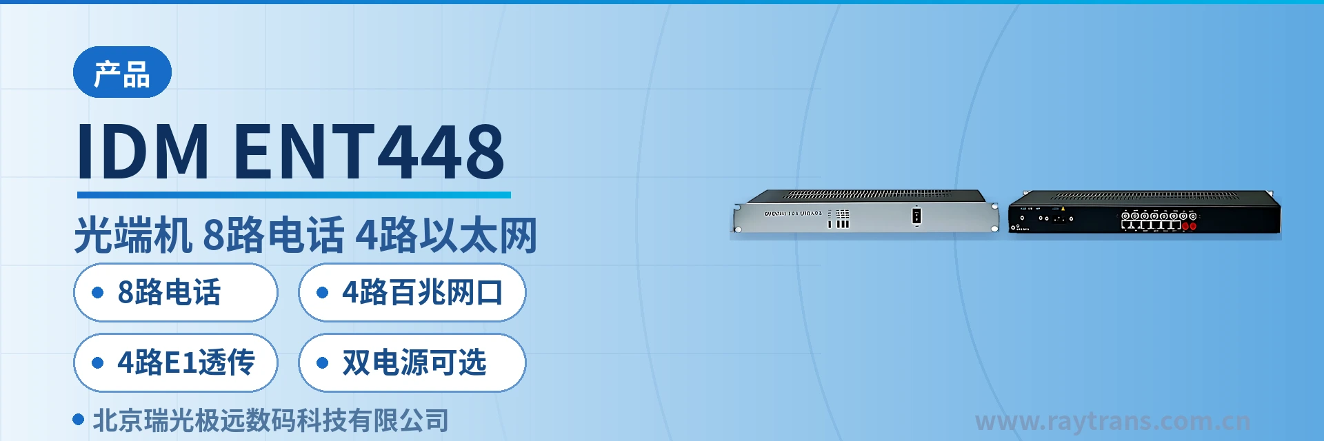
IDM-ENT448 Telephone Optical Multiplexer
8 Telephone, 4 Ethernet, 4 E1 Single-Fiber Multiplexing — One Unit Replaces Three, Saving Rack Space and Links
The IDM-ENT448 multi-service optical multiplexer provides a 155M optical interface in a standard 19-inch 1U chassis. The IDM-ENT448 multi-service optical multiplexer provides 8 telephone channels + 4 shared 100M Ethernet channels (VLAN partitioning supported) + 4 E1 transparent channels, with 220V/-48V optional dual power supply.
IDM-ENT448 is an 8-telephone, 4-Ethernet, 4-E1 telephone optical multiplexer developed by Beijing Ruiguang Jiyuan Digital Technology Co., Ltd. (Raytrans), used to multiplex 8 analog telephone channels, 4 Fast Ethernet channels and 4 E1 services onto a single 155Mbps optical transmission channel. As a professional optical multiplexer manufacturer, Raytrans highlights in its product showcase that the device uses a standard 19-inch 1U chassis, offers AC 220V and DC -48V power supply modes with optional dual power supplies, and that a single unit can handle the voice, data and trunk access of one private network site. This telephone optical multiplexer combines the technical characteristics of a multi-service optical multiplexer and a PDH optical multiplexer, and is suitable for scenarios such as government private network optical fiber communication solutions and military emergency communications vehicle solutions. The unit meets private network access requirements with the high reliability and flexible networking capability of an optical multiplexer.
Key Specifications at a Glance: 8 telephone channels · 4 Fast Ethernet ports · 4 E1 transparent channels · optional dual power supplies · 155Mbps optical port · receiver sensitivity better than -36dBm
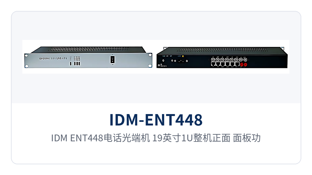
Figure 1: IDM-ENT448 telephone optical multiplexer, 19-inch 1U unit front view, panel function control switch and power/optical path alarm indicator LEDs
What Is an 8-Telephone, 4-Ethernet, 4-E1 Telephone Optical Multiplexer
An 8-telephone, 4-Ethernet, 4-E1 telephone optical multiplexer is a type of point-to-point transmission device that aggregates three types of services—voice, data and E1 trunk—into the same pair of optical fibers, where 8 telephone, 4 Ethernet and 4 E1 correspond to the number of telephone channels, Ethernet ports and E1 channels respectively. The positioning of IDM-ENT448 is to replace three single-service devices with one 1U chassis, so that a remote station occupies only one rack unit and uses only one optical link, which is a typical product showcase form of a multi-service optical multiplexer.
The chassis dimensions are 440×230×45mm, occupying only 1U of space in a standard 19-inch cabinet, and the panel is provided with a function control switch and alarm indication. Substation communication panels, station communications equipment rooms and duty post cabinets with tight cabinet space only need to reserve 1U, and adjacent rack units can still be left for other service devices.
From the wiring perspective, the on-site division of the three service types is clear: telephone ports connect to telephones or subscriber boards, Ethernet ports connect to data devices and cameras, and E1 ports connect to existing PCM or exchange-side digital trunks. As a 1U rack-mounted telephone optical multiplexer, IDM-ENT448 provides all interfaces to common industry standards, so the construction team can wire according to existing cabling practices without adding conversion devices for any service type.
Key Specifications: Optical Port, Telephone, E1 and Ethernet Parameters
The following tables list the capabilities of IDM-ENT448 in two groups: functions and performance. The function table covers chassis structure, service interfaces and O&M functions, while the performance table covers the optical port, telephone, E1, Ethernet, power supply and environmental conditions. Use the rows when checking a configuration list, preparing a tender response or performing a link power budget; the parameter definitions and applicable conditions are listed together.
Function Overview
| Function | Description |
|---|---|
| 8-channel telephone access | Provides 8 analog telephone interfaces with caller ID support, and can connect to telephones, fax machines and exchange-side subscriber interfaces |
| 4-channel shared 100M Ethernet | 4 RJ-45 Fast Ethernet electrical ports share a line-rate 100M bandwidth, and VLANs can be partitioned to isolate services |
| 4-channel E1 transparent transmission | 4 E1 channels are carried in transparent transmission mode without changing frame content, used for trunk extension or connecting to existing PCM and SDH equipment |
| Single-fiber 155M multiplexing | Telephone, Ethernet and E1 services are multiplexed onto one 155Mbps optical channel, and a pair of optical fibers completes site interconnection |
| Optional dual power supplies | AC 220V and DC -48V power supply modes are available with optional dual power supplies, ordered according to site power supply conditions |
| Alarm and function control | The panel provides a function control switch and alarm indication, and power, optical path and service status can be read directly on the front of the unit |
| 1U rack installation | Standard 19-inch 1U chassis, 440×230×45mm, occupying 1U of installation space in a standard cabinet |
Interface and Performance Specifications
| Item | Parameter/Specification | Description/Applicable Conditions |
|---|---|---|
| Optical interface type | FC (SC and others can be customized) | Selected according to the on-site optical cable termination method |
| Fiber mode | Single-mode (multimode optional) | Selected according to link conditions, configured as a pair at the transmit and receive ends |
| Optical line rate | 155Mbps±50ppm | The three service types share the same optical channel |
| Wavelength | 1310nm | Configured as a pair with the peer device |
| Transmit optical power | -2 to -11dBm | Output optical power range at the transmit side |
| Receiver sensitivity | Better than -36dBm | Lower limit of optical power for normal operation at the receive side |
| Telephone interface | Audio range 300Hz to 3400Hz, impedance three-element composite 200Ω+560Ω//0.1μF | A-law compression per ITU G.711, loop current 25mA per channel |
| E1 interface | Bit rate 2048Kbps, line code HDB3, supports ITU-T G.703, impedance 75Ω/120Ω | Frame structure PCM30/31, channel-associated signaling |
| Ethernet interface | RJ-45, 10/100Base-T, 10M/100M | Supports IEEE802.3, adaptive half-duplex/full-duplex |
| Power supply mode | DC -48V or AC 220V | Both modes available with optional dual power supplies |
| Overall power consumption | 40W±10% | Calculated on a whole-unit basis, with all services working simultaneously |
| Operating temperature | 0℃ to 40℃ | Humidity ≤90% (non-condensing) |
| Dimensions | 440×230×45mm | 19-inch 1U chassis, standard cabinet installation |
How the Three Service Types Coexist on the Same Optical Fiber Without Interference
Voice is compressed inside the device into a 64Kbit/s bit stream using A-law per ITU-T G.711, loaded into E1 time slots of the PCM30/31 frame structure, and then multiplexed together with Ethernet services onto the 155Mbps optical channel. The E1 interface has a bit rate of 2048Kbps and HDB3 line code, complies with ITU-T G.703, offers selectable 75Ω or 120Ω impedance, uses channel-associated signaling, and is transparent to frame content. This multiplexing mechanism is a typical implementation of PDH optical multiplexers and multi-service optical multiplexers in private network scenarios.
The three service types each use independent channels inside the device, neither rewriting each other nor occupying each other's bandwidth. Telephone channels are allocated one by one in 64K time slots, with 8 lines per unit; E1 channels keep the 2048Kbps frame structure and HDB3 line code unchanged for transparent transmission; Ethernet channels are framed separately.
- Telephone channel: analog voice channels enter 64K time slots after G.711 encoding, with 8 independent lines, a loop current of 25mA per channel and an audio range of 300Hz to 3400Hz; call quality is measured against narrowband voice standards.
- E1 channel: 4 E1 channels are carried in transparent transmission mode with a bit rate of 2048Kbps and PCM30/31 frame structure; the frames received by the peer device are identical to those at the source, and trunk signaling is not affected by intermediate processing.
- Ethernet channel: 4 RJ-45 electrical ports share a line-rate 100M, comply with IEEE802.3, are adaptive half-duplex/full-duplex, and after VLAN partitioning the data of different services is invisible to each other.
The on-site value of unified interface standards is that wiring is consistent with existing systems. The exchange side accesses via E1 digital trunk or analog subscriber interface, the user side assigns numbers by telephone, and the data side uplinks via RJ-45, so the engineering team does not need to add protocol conversion devices for any service type. For an optical multiplexer manufacturer, this standardized interface design also lowers the threshold for on-site work and later maintenance.
What Receiver Sensitivity Better Than -36dBm Means for Weak-Light Long-Distance Links
Receiver sensitivity better than -36dBm means the receive side can still correctly recover service signals when the optical power is as low as -36dBm, which is a hard metric for judging how far an optical fiber link can reach. Based on the lower transmit optical power limit of -11dBm and the sensitivity of -36dBm, the allowable optical power budget of the link is about 25dB, and this weak-light margin is exactly the fault tolerance space for long-distance links with many connectors.
Based on the typical attenuation of 0.35dB/km for ITU-T G.652 single-mode fiber in the 1310nm window, a 25dB budget can still cover station spacing on the order of tens of kilometers after deducting adapter and splice point losses. In engineering practice, calculate section by section according to the actual distance, number of connectors and fiber aging, and finalize the optical module and optical port type after reserving maintenance margin.
The significance of stable weak-light carrying for private network sites lies in fault tolerance. Old lines have many connectors, attenuation increases in the rainy season, and losses accumulate after repeated optical cable cutovers—all of which drive received optical power down, and equipment with sufficient sensitivity margin will not drop calls or lose packets because of this. During commissioning and annual inspection, measure the received optical power with an optical power meter and compare it with the -36dBm sensitivity threshold to determine whether the link still has margin. In government private network optical fiber communication solutions and military emergency communications vehicle solutions, this weak-light fault tolerance is often a mandatory assessment item in link design.
What Kind of Sites Suit Optional Dual Power Supplies and 40W Power Consumption
IDM-ENT448 supports DC -48V and AC 220V power supply modes and offers optional dual power supplies. Communications equipment rooms connect -48V DC to the power distribution cabinet or battery bank, while sites with only mains power choose the AC 220V model. With dual power supply configuration, the two power feeds are drawn from different circuit breakers, and services keep running when one feed fails—a power supply structure valued by unattended sites.
The overall power consumption is 40W±10%, calculated on a whole-unit basis, equivalent to the electricity use of one lighting lamp at a site. Low power consumption means more margin for battery backup time, less heat inside the chassis, a lighter load on equipment room air conditioning, and easier assurance of heat dissipation space in a 1U chassis.
- Before power-on check: confirm the voltage level and polarity, circuit breaker capacity and grounding method; the two feeds of dual power supplies are drawn from different circuit breakers.
- During operation watch: whether the chassis alarm indication and power status indication are normal, and observe whether calls and data remain stable during battery discharge tests.
- During maintenance recheck: after replacing a power supply module or changing the power supply mode, recheck the circuit breaker capacity and grounding to avoid the two power feeds sharing one circuit breaker.
As an optical multiplexer manufacturer, Raytrans provides selection support in the product showcase and solution delivery of telephone optical multiplexers, PDH optical multiplexers and multi-service optical multiplexers according to the above power supply and O&M definitions, facilitating the on-site implementation of government private network optical fiber communication solutions and military emergency communications vehicle solutions.
How to Install and Commission
Installation and commissioning proceed in five stages: chassis placement, optical path termination, power supply connection, interface matching and power-on verification, recording the correspondence between interfaces and services after each step. This record is the direct basis for subsequent expansion, fault location and O&M handover; simply check item by item on site in the following order.
- Chassis placement: secure the 19-inch chassis in 1U of space in a standard cabinet, position the wiring area and cable trays according to the construction drawing, and leave space at the front and rear of the chassis for heat dissipation and cabling.
- Optical path termination: the optical interface is FC (SC and others can be customized), single-mode fiber (multimode optional), and the 1310nm wavelength is configured as a pair with the peer end; clean adapters and pigtails one by one.
- Power supply connection: connect -48V DC or 220V AC according to site conditions; when optional dual power supplies are selected, draw the two feeds from different circuit breakers and ensure proper grounding.
- Interface matching: connect telephone ports to telephones or exchange-side subscriber boards, wire E1 with 75Ω coaxial or 120Ω balanced cables, and connect Ethernet ports to data devices with VLAN membership labeled.
- Power-on verification: observe the panel power, optical path and alarm indications, spot-check the call quality of the 8 voice channels, the bit errors of the 4 E1 channels and the Ethernet link status, and measure the received optical power and record it for archiving.
Differentiated Value
The three capabilities of the 8-telephone, 4-Ethernet optical multiplexer correspond respectively to rack space, link margin and power supply conditions; the following table maps each capability to its on-site value. When comparing selections and prices, extract the required items by row; project responses and commercial price comparisons can use the same set of facts, and the descriptions in the table are consistent with the parameter table.
| Differentiation Point | Specific Capability | Corresponding On-Site Value |
|---|---|---|
| 8-channel telephone, 4-channel Fast Ethernet and 4-channel E1 multiplexed over the same fiber | 8-channel telephone, 4-channel shared 100M Ethernet (VLAN-capable) and 4-channel E1 transparent transmission multiplexed onto one 155Mbps optical channel | A site uses only one 1U device and a pair of optical fibers, so rack positions, the number of fiber cores and the number of devices are all reduced at the same time |
| Receiver sensitivity better than -36dBm | Transmit optical power -2 to -11dBm, receiver sensitivity better than -36dBm, link budget about 25dB | Telephone and data services remain stable over weak-optical, long-distance and multi-connector links, reducing investment in repeaters and upgrades |
| Optional dual power supply and 40W power consumption | AC 220V and DC -48V optional dual power supply, overall power consumption 40W±10% | The unit can be deployed in both equipment room DC and site mains power environments, with more margin for storage battery backup duration |
Typical Application Scenarios
The three types of private networks place different emphasis on the configuration of the IDM-ENT448: electric power private networks value the compatibility of voice channels and E1 trunks, rail transit values unified spare parts for sites along the line, and military and government private networks place more emphasis on power supply continuity and link independence. The following describes the networking position and configuration points by industry.
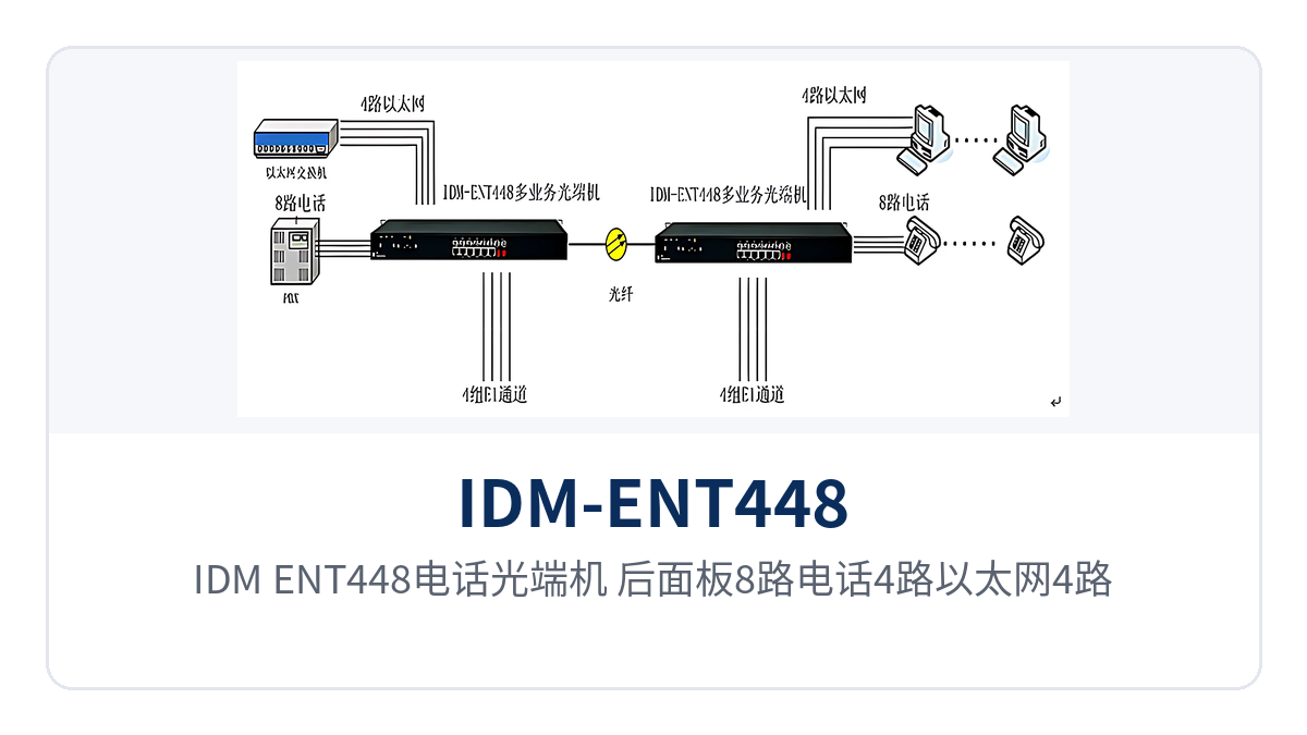
Figure 2: IDM-ENT448 telephone optical multiplexer rear panel layout of 8 telephone, 4 Ethernet and 4 E1 interfaces and point-to-point networking schematic
Electric Power Private Network: Dispatch Telephone and Telecontrol Data Backhauled over the Same Fiber
Substations and power supply stations are distributed along the line, and it is necessary both to ensure continuous availability of dispatch telephone and to backhaul telecontrol data and in-station surveillance to the dispatch center. The IDM-ENT448 handles access on the substation side: dispatch and administrative telephones are provisioned on the 8 telephone interfaces, the trunk to the dispatch center is extended over the 4 E1 channels, and telecontrol data and surveillance backhaul run over the Fast Ethernet ports.
The substation communication panel reserves a 1U rack position, and the device and wiring units are arranged adjacent to each other, keeping the inspection and replacement path short. When voice channels are insufficient, a higher-capacity model is selected according to the site traffic, while the interface type and wiring practice remain the same set, so wiring does not need to be redone during upgrades.
Rail Transit: Centralized Voice Channel Access for Stations and Section Duty Points
Stations, depots and section duty points of rail transit are distributed along the line, the number of telephones at each station varies greatly with station class, and E1 channels are also needed between stations to carry dedicated communication services. The IDM-ENT448 is configured according to the site service list, with the 4 E1 channels used for inter-station trunk extension and the 4 Ethernet ports carrying station service data and video backhaul.
The 19-inch 1U chassis facilitates unified installation in the communications equipment room, and sites along the line share spare parts of the same model, reducing the variety of spare parts. Section duty points are mostly unattended, and the optional dual power supply and 40W-class power consumption place low demands on storage battery capacity and equipment room heat dissipation.
Military and Government Private Network: Independent Transmission of Duty Post Telephone and Private Network Data
Military and government private networks have clear requirements for call availability and link independence, and communications between duty posts, stationed points and command nodes are organized independently over the private network. The IDM-ENT448 handles access on the duty post side: the exchange side is connected via E1 or analog subscriber interfaces, subscriber lines are provisioned to telephones at each job role on the user side, private network data is uplinked through the Ethernet ports, and the three types of services share one optical fiber.
The device is installed in a cabinet, and the panel alarm indication and port numbering are the basis for on-site positioning; replacing the unit with a spare according to the numbering restores services, so communication recovery at the site does not depend on manufacturer attendance on site. Duty posts usually do not have professional maintenance resources, the panel indication is intuitive enough, and duty personnel can report the failure location clearly over the telephone.
Conclusion
The 8-telephone 4-Ethernet 4-E1 telephone optical multiplexer packs three types of services into one 1U device: the IDM-ENT448 carries 8-channel telephone, 4-channel shared 100M Ethernet and 4-channel E1 transparent transmission simultaneously over one 155Mbps optical channel, with receiver sensitivity better than -36dBm, optional 220V and -48V dual power supply, and overall power consumption of 40W±10%.
For electric power, rail transit and military and government private networks, the value lies in that a site occupies only a 1U rack position and uses only a pair of optical fibers, weak-optical long-distance links still have margin, and both equipment room DC and site mains power supply environments can be accommodated. The specific interface type, power supply format and optical fiber distance are determined according to site conditions, and the parameters are subject to the manufacturer's technical documentation and commercial confirmation.


