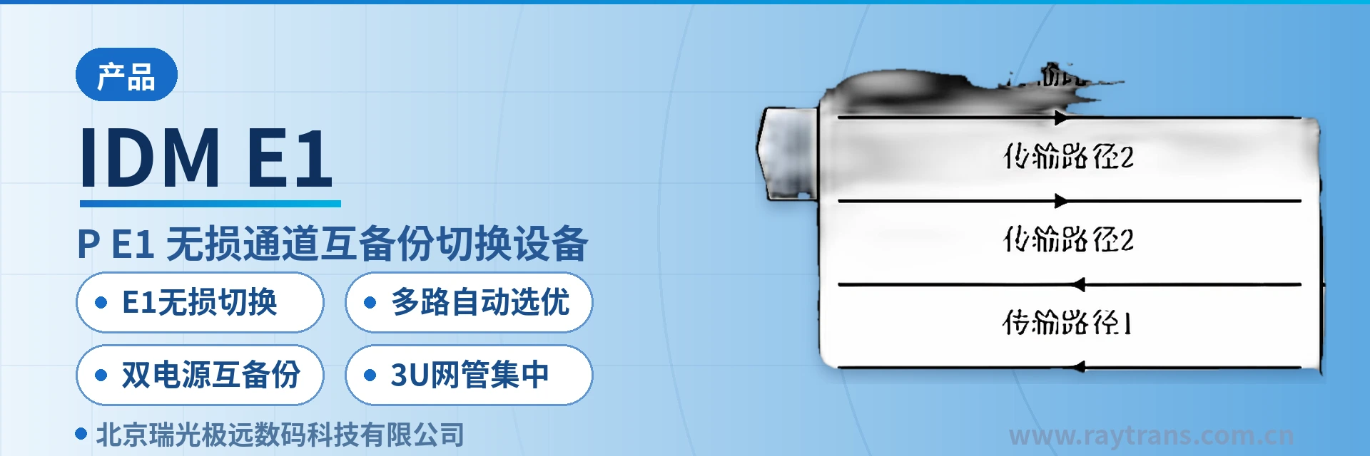
IDM E1_DUP E1 Channel Mutual Backup Switching Equipment
One E1 split into multiple paths with automatic optimal selection; lossless switching without data loss; fast command response for impaired switching
Some important remote dispatch and control sites (such as subways, airports, and military sites) often require very high system reliability and frequently use services over two or more transmission networks (for example, leased channels from China Unicom and China Mobile respectively, or mutual backup between satellite and terrestrial networks
IDM E1_DUP E1 channel mutual backup switchover equipment is a one-to-multiple backup and optimal selection device developed by Beijing Ruiguang Jiyuan Digital Technology Co., Ltd. It is used to split one E1 channel into multiple channels and feed them into different transmission networks, and at the remote end automatically detect the quality of each path and select the usable one. As a professional SDH equipment manufacturer, Raytrans has incorporated mature SDH technology and product showcase concepts into this device to ensure stable operation of the E1 channel mutual backup switchover equipment in various scenarios.
Remote dispatch and control sites such as subways, airports, and military facilities often carry the same service over two or more transmission networks, for example by leasing channels from China Unicom and China Mobile respectively, or by using satellite and terrestrial networks as mutual backup. Such sites require subscriber terminals to automatically select a normal transmission network and channel, so that a single link failure does not directly interrupt dispatch services. As a command and dispatch system manufacturer, Raytrans can provide military emergency communications vehicle solutions and government private network optical fiber communication solutions, achieving multi-path carriage through SDH equipment and ensuring service continuity with E1 lossless switchover mechanisms.
Key Specifications at a Glance: E1 lossless switchover · multi-path automatic optimal selection · dual mutual-backup power supplies · 3U centralized network management · one E1 to multiple parallel paths · cascading expansion for more paths
How does the E1 channel mutual backup switchover equipment avoid information loss before and after switchover?
E1 channel switchover falls into two categories, lossy switchover and lossless switchover, and the difference lies in which path's delay the transmitter aligns data to. E1 lossless switchover takes the highest delay among all paths as the transmission reference, first buffering and aligning the data on the faster paths before sending it out uniformly, so that at the instant of switchover the data on the new channel matches the old channel exactly, with no information lost before or after switchover.
E1 lossy switchover forwards directly according to the lowest delay among all paths, so commands travel over the faster path, at the cost of possibly losing a small amount of data at the instant of path change. Leased channels have different transmission delays, and this delay difference is exactly the dividing point between the two modes and an on-site condition that must be measured before SDH equipment selection.
The two modes correspond to two types of service requirements, and selection can be decided by whether the service allows data loss. Power dispatch, remote control and telemetry, and protection signals do not allow data loss during path change, so E1 lossless switchover is chosen; sites such as military and air traffic control that issue commands by voice value the speed at which commands arrive, so lossy switchover is chosen. Raytrans IDM E1_DUP builds both modes into the same device, with the switchover mode configured according to the nature of the on-site service, and different channels within the same chassis can be set separately.
How is one E1 split into multiple paths with automatic optimal selection?
IDM E1_DUP splits one E1 into multiple parallel transmissions, and the remote end automatically completes channel selection through three steps: splitting, detection, and optimal selection, without requiring subscriber terminals to make judgments themselves. When more than three paths are needed, cascading multiple SDH devices expands the number of paths, which is determined by the number of transmission networks available on site.
- Splitting: one E1 entering the device is replicated into multiple paths and fed into networks of different carriers or different transmission means.
- Detection: the remote end continuously compares the transmission quality of each E1 path, identifying both link interruption and quality degradation, with criteria that do not rely on manual coordinated testing at both ends.
- Optimal selection: the path with acceptable quality is selected as the output, and the service-side device receives the currently available channel, with path change transparent to upper-layer services.
Detection and optimal selection are completed in a closed loop within the remote device, and after service recovery the system automatically returns to the normal path, so on-duty personnel do not need to go on site to rewire. The same multi-path approach in the IDM series also covers telephone channels, pure audio channels, and RS232/RS485 channels, with E1 being just one of the carried objects.
What are the main functions?
The functions of the E1 channel mutual backup switchover equipment revolve around four main lines: splitting, detection, optimal selection, and switchover control. Each function and its purpose are shown in the table below. Use the table to check against on-site configuration and O&M approach; interface quantities and capacities not listed in the table are subject to ordering configuration.
| Function | Description |
|---|---|
| One E1 split into multiple transmissions | Splits one E1 channel into multiple parallel paths fed into different transmission networks, with cascading supporting more paths |
| Remote quality detection | Automatically detects the transmission quality of each transmission channel at the remote end, providing the basis for optimal selection |
| Automatic optimal selection and switchover | Automatically selects one path with acceptable transmission quality as output, reducing service interruption caused by link failure |
| E1 lossless switchover | Aligns and sends according to the highest delay among all paths, with no information lost before or after switchover |
| E1 lossy switchover | Forwards directly according to the lowest delay among all paths, so commands arrive faster |
| Network management monitoring and switchover | Monitoring and switchover of E1 channels are performed through Ethernet network management, with switchover conditions set by the network management system |
| Manual forced switchover | Manual forced switchover via the network management system or DIP switches, with manual switchover taking higher priority |
| Mode indication | The current status of the automatic, network management, and manual modes is indicated by panel indicator LEDs |
| Dual mutual-backup power supplies | The centralized 3U rack is configured with dual mutual-backup power cards, so power supply does not become a new single point |
Key Specifications and Performance Specifications
The form factor, splitting capability, and switchover modes of IDM E1_DUP are listed item by item in the table below, with specifications subject to the product documentation. Power supply, power consumption, and mechanical dimensions not listed in the table are subject to the SDH equipment manufacturer's technical documentation and ordering configuration; the items in the table are used for solution configuration and on-site verification.
| Item | Parameter/Specification | Description/Applicable Conditions |
|---|---|---|
| Device model | IDM E1_DUP | E1 channel mutual backup switchover equipment |
| Splitting capability | One E1 split into multiple transmissions, with cascading supporting more paths | Configured according to the number of transmission networks simultaneously carrying services on site |
| Switchover modes | E1 lossless switchover, E1 lossy switchover | Selected according to whether the service allows data loss |
| Lossless reference | Aligns and sends according to the highest delay among all paths | Applicable to services such as electric power that do not allow data loss |
| Lossy reference | Forwards directly according to the lowest delay among all paths | Applicable to voice command services such as military and air traffic control |
| Centralized form factor | 3U architecture, unified Ethernet network management card, dual mutual-backup power cards | Suitable for centralized deployment in equipment rooms and unified duty over multiple channels |
| Desktop form factor | 2 sets of E1 mutual backup channel selectors | Suitable for sites with few points requiring on the spot operation |
| Switchover modes | Automatic switchover, network management switchover, manual switchover | Manual forced switchover takes higher priority |
| Network management capability | Channel monitoring and switchover are implemented through Ethernet network management, with switchover conditions set by the network management system | The centralized type is managed uniformly through the network management card |
| Applicable services | E1 channels, telephone channels, pure audio channels, RS232/RS485 channels | The IDM series supports multi-path transmission and active optimal path selection transmission |
| Applicable sites | Subway and rail transit dispatch, airport and air traffic control command, military and electric power private networks | Remote dispatch and control sites and important service nodes |
| Power supply and power consumption | Not yet recorded in the knowledge base | Subject to the manufacturer's technical documentation and ordering configuration |
What scenarios are the centralized 3U and desktop devices respectively suited for?
The centralized device is a 3U architecture equipped with a unified Ethernet network management card and dual mutual-backup power cards, and both monitoring and switchover of E1 channels can be implemented through the network management system. Switchover conditions are set by the network management system, and switchover can be automatic or manually forced via the network management system or DIP switches. Dual mutual-backup power cards keep the power supply from becoming a new single point, and for lines under centralized duty in equipment rooms, carrying multiple channels on one 3U device is easier to maintain.
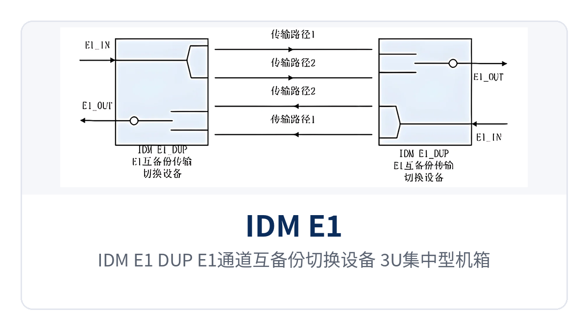
Figure 1: Close-up of the Ethernet network management card and dual power cards on the front of the IDM E1_DUP E1 channel mutual backup switchover equipment 3U centralized chassis
The desktop device provides 2 sets of E1 mutual backup channel selectors and is smaller in size, suitable for sites with only one or a few points requiring manual intervention. When performing on-site link disconnection verification, or when a channel needs to be directly designated according to the command relationship, operating on the device panel on the spot is more intuitive than issuing commands remotely. Form factor selection depends on two things: the number of channels and the O&M approach. If channels are concentrated in an equipment room, choose the 3U centralized type; if points are scattered and on-site operation is required, choose the desktop type.
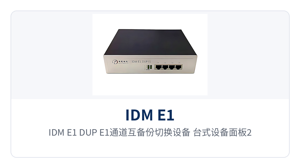
Figure 2: 2 sets of E1 mutual backup channel selectors and status indicator LEDs on the panel of the IDM E1_DUP E1 channel mutual backup switchover equipment desktop device
Differentiation Point
The four capabilities correspond respectively to four types of on-site pain points: data loss during path change, single path, power supply single point, and scattered O&M. They are listed item by item in the table below, making it easy to check configuration content and commercial terms against project points to consider. During verification, compare item by item according to service nature and O&M approach; any missing item is what needs to be confirmed with the SDH equipment manufacturer.
| Differentiation Point | Customer Value |
|---|---|
| E1 lossless switchover | No information is lost before or after E1 channel switchover, meeting the needs of services such as electric power that do not allow data loss |
| Multi-path automatic optimal selection | One E1 is split into multiple transmissions with cascading expansion support, and the remote end automatically detects the quality of each path and selects the available one |
| Dual mutual-backup power supplies | The centralized 3U rack has dual mutual-backup power cards, so the power supply does not become a new single point |
| 3U centralized network management | The network management system uniformly monitors and sets switchover conditions, and manual forced switchover takes higher priority |
Typical Application Scenarios
The reason remote dispatch and control sites need such SDH equipment is that the services themselves must not fail together with a single link. During networking, one device is deployed at each end: the splitting side sends out multiple paths and the optimal selection side receives one path, with the intermediate hops traversing networks of different carriers or different transmission means, so that any link failure does not affect service output.
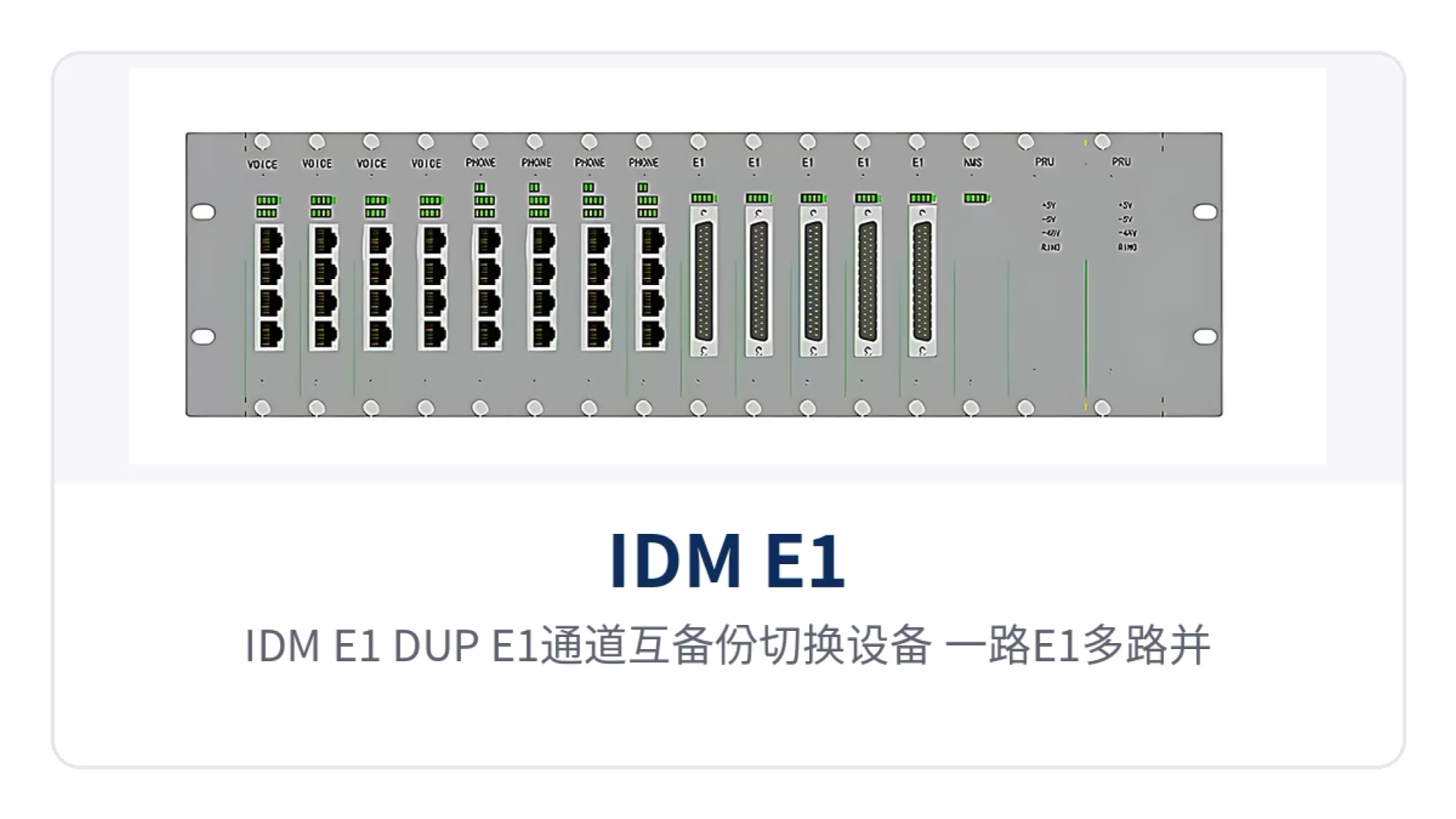
Figure 3: Schematic of the networking topology for one E1 multi-path parallel transmission and remote automatic optimal selection of the IDM E1_DUP E1 channel mutual backup switchover equipment
Rail transit dispatch: how dispatch orders avoid loss before and after switchover
Subway dispatch carries the voice and data of train dispatch, power dispatch, and environment control dispatch, and multi-network redundancy is a routine requirement. Subways often lease channels from two carriers at the same time, sending the same E1 service to stations and depots over two networks respectively. The E1 channel mutual backup switchover equipment splits one E1 into multiple paths at the station side, and the remote end selects the available path according to transmission quality; E1 lossless switchover ensures no information loss before and after switchover, so dispatch orders are not interrupted by degradation of a single link.
The centralized 3U device is placed in the communications equipment room, with dual mutual-backup power cards and switchover conditions set by the network management system, so the duty operator can view the status of each E1 channel on the network management system. For lines with many stations requiring unified management, one centralized device carries multiple channels, and adjustment of switchover conditions does not require visiting each station.
Airport air traffic control command: how multi-path E1 automatic optimal selection shortens command latency
Airport ground dispatch and air traffic control command cover apron guidance, passenger services, and ground support, and interruption of any channel affects the pace of flight support. Airports usually have both self-built transmission networks and leased channels, and in some scenarios satellite links are used as a supplement. The device feeds the same E1 into multiple links simultaneously, and the remote end automatically detects the quality of each path and selects the available one; voice services adopt E1 lossy switchover, so commands travel over the path with lower latency in exchange for faster arrival.
Sites with higher requirements can cascade multiple devices to expand more paths and retain a manual forced switchover entry, so that in case of dispute the on-duty personnel can directly designate the path. The path change process does not require on-site rewiring, and the duty operator can see channel status on the network management system.
Military and electric power private networks: how dual-network mutual backup and dual power supplies work together
Military remote command has high requirements for redundancy and controllability, and often uses satellite and terrestrial networks as mutual backup to carry commands and data. In the military emergency communications vehicle solution provided by Raytrans, the device splits and sends at the command post side and performs optimal selection and reception at the remote end, supporting three switchover modes: automatic, network management, and manual. Manual forced switchover takes higher priority, making it easy to directly designate a channel according to the command relationship in a combat readiness state.
Electric power private networks place greater emphasis on data integrity. Remote control, telemetry, and protection signals must not lose data during path switching. In such cases, E1 lossless switching is enabled, and signals are aligned according to the highest latency value among the channels before transmission. The dual mutual-backup power supplies of the centralized 3U rack give both the power supply and the transmission link redundancy, so services at important substations and dispatch centers are not terminated due to a single point of failure. As a command and dispatch system manufacturer, Raytrans can also provide supporting SDH equipment and product showcase support for government private network optical fiber communication solutions.
Conclusion
As an E1 channel mutual backup switching device, the IDM E1_DUP combines four capabilities in a single unit: E1 lossless switching, automatic multi-channel selection, dual mutual-backup power supplies, and 3U centralized network management. One E1 channel is split into multiple parallel channels, and the remote end automatically selects the best one based on transmission quality. A link failure no longer directly becomes a service interruption, and services such as electric power that do not allow data loss can maintain information integrity during path switching.
The selection sequence is to first confirm the number of available on-site channels and the carrier, then determine lossless or lossy mode according to whether the service allows data loss, and finally choose a 3U centralized or desktop device according to channel scale and O&M approach. The more independent the channels are, the more obvious the actual effect of mutual backup; when two links run over the same optical cable or the same transmission device, the backup capability decreases accordingly.