
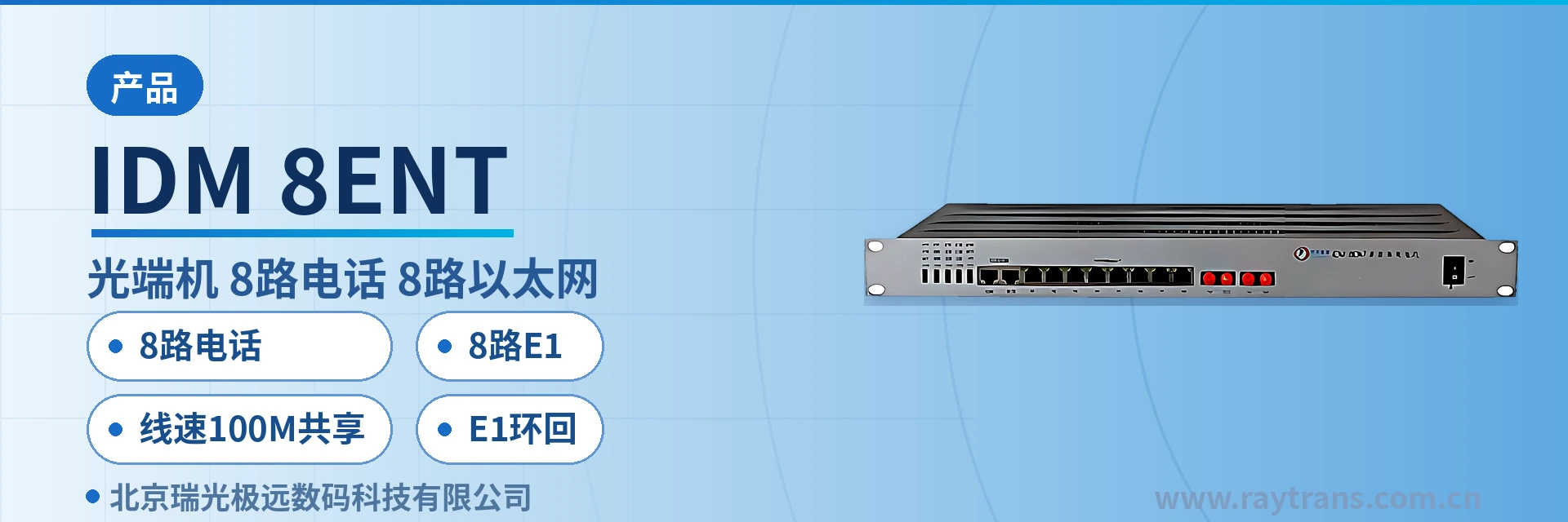
IDM-8ENT Telephone Optical Multiplexer
8 telephone channels, 8 E1 channels, and 8 Ethernet channels over the same fiber; saves three transmission devices
The IDM-8ENT multi-service optical multiplexer provides a 155M optical interface in a standard 19-inch 1U chassis. The IDM-8ENT multi-service optical multiplexer provides 8 shared 100M Ethernet channels + 8 groups of transparent E1 + 8 telephone channels + 2 high-speed RS232 channels, with 220V/-48V optional
The IDM-8ENT 8-channel telephone and 8-channel E1 optical multiplexer is a 155M multi-service optical multiplexer developed by Beijing Ruiguang Jiyuan Digital Technology Co., Ltd. (Raytrans). A single 19-inch 1U chassis provides 8 telephone channels, 8 E1 channels, and 8 Ethernet interfaces at the same time, with all three service types carried over one optical fiber. As a professional optical multiplexer manufacturer, Ruiguang Jiyuan continues the integrated design approach of the multi-service optical multiplexers in its product showcase with this product. The device is used in pairs: the central office side connects to the analog subscriber or digital trunk resources of a switch, while the remote side restores telephone, E1, and Ethernet interfaces. A site side needs only a pair of optical fibers for service activation, making the device suitable for scenarios such as government private network optical fiber communication solutions and military emergency communications vehicle solutions; the series also covers different forms such as PDH optical multiplexers, facilitating selection as required.
Key Specifications at a Glance: 8 telephone channels · 8 E1 channels · 8 Ethernet interfaces · wire-speed 100M shared · E1 loopback · 220V/-48V selectable
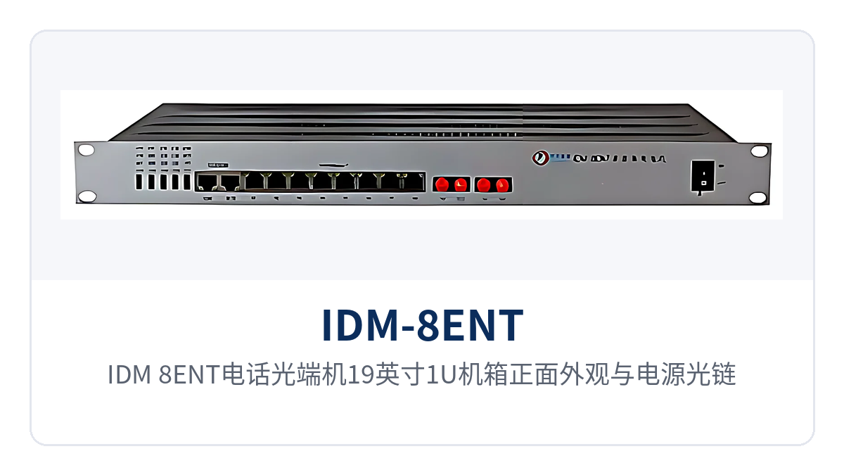
Figure 1: Front view of the 19-inch 1U chassis of the IDM-8ENT telephone optical multiplexer with power and optical link indicator LEDs
What Kind of Device Is an 8-Channel Telephone and 8-Channel E1 Optical Multiplexer?
The IDM-8ENT 8-channel telephone and 8-channel E1 optical multiplexer belongs to PCM integrated service optical fiber transmission equipment. It is a typical multi-service optical multiplexer whose role is to multiplex narrowband voice, E1 digital dedicated lines, and Ethernet data onto a single 155M optical fiber, replacing the practice of equipping each service type with its own transmission device. Urban sites use it to overcome the bandwidth and transmission distance constraints of twisted pair, while suburban sites use it for cross-boundary line extension and to replace remote small offices and deferred switching offices; both scenarios share the same access equipment. As an integrated service model in the PDH optical multiplexer family, it is often classified in the product showcase under the intersection of telephone optical multiplexers and multi-service optical multiplexers.
The reason a single 155M optical fiber can carry three service types simultaneously is that different services are divided into mutually independent channels: each voice channel is encoded into one time slot at 64 Kbps, E1 is transparently transmitted as a whole at 2.048 Mbps, and Ethernet is frame-switched and then shared within the allocated bandwidth. The three channel types are separated inside the device and do not occupy each other's time slots or bandwidth, so telephone ringing, E1 dedicated lines, and Ethernet data can all be online at the same moment.
How the Three Services Share One Fiber: 8 Telephone Channels, 8 E1 Channels, 8 Ethernet Interfaces, and 2 RS232 Channels
The three services sharing one fiber comes down to interface counts and channel attributes: telephone, E1, and Ethernet are each grouped separately and are not converted into one another. The table below lists the capabilities and applicable conditions of the IDM-8ENT item by item by function. When checking, first count the voice channels and E1 directions, then check the number of Ethernet ports and the power supply format, and then confirm whether serial port devices need to be sent over the fiber.
| Function | Description |
|---|---|
| 8-channel telephone service interface | A single unit provides 8 telephone channels; the central office side connects to the analog subscriber or digital trunk resources of a switch, and the remote side directly connects telephones, completing cross-boundary line extension |
| 8-channel E1 transparent transmission | Provides 8 groups of E1 channels, transparently transmitted as a whole at 2.048 Mbps, and can connect to existing PCM, SDH, or switching equipment without service reassembly |
| 8-channel Ethernet shared wire-speed 100M | 8 groups of Ethernet channels share wire-speed 100M bandwidth; each channel can be partitioned into VLANs as required and isolated by service network segment |
| 2 high-speed RS232 channels | Provides 2 high-speed RS232 data channels, sent over the optical fiber together with voice channels and Ethernet, for remote access of serial port devices |
| Comprehensive monitoring | Panel alarms and line monitoring allow timely assessment of line operating conditions, enabling the equipment room side to locate the fault direction |
| E1 channel local and remote loopback | E1 channels support local loopback and remote loopback; with both ends working together, the fault section can be determined remotely at unattended sites |
| Dual power supply formats selectable | 220V and -48V power supply formats are selectable, so AC equipment rooms and DC communication sites can both draw power directly according to on-site power conditions |
| 19-inch 1U chassis | The standard 1U chassis fits into a communications cabinet and occupies one rack position, so sites do not need to reserve additional space for the device |
Key Specifications and Interface Specifications
Parameters are listed in groups by optical interface, Ethernet, E1, telephone, serial port, and power supply. Service interfaces and the optical interface are concentrated on the rear panel; during wiring, check each channel against the interface silkscreen. Items not given in the product documentation are marked as not yet recorded in the knowledge base; confirm with the optical multiplexer manufacturer before ordering to avoid designing and quoting based on assumed values.
| Item | Parameter/Specification | Description/Applicable Conditions |
|---|---|---|
| Optical interface rate | 155M | The three service types are carried over one 155M optical fiber link |
| Optical interface type | not yet recorded in the knowledge base | The optical module and interface type are subject to the ordering configuration |
| Transmission distance | not yet recorded in the knowledge base | Calculated according to the selected optical module and link loss; confirm at project ordering |
| Ethernet interface | 8 groups, shared wire-speed 100M | Each channel can be partitioned into VLANs as required; bandwidth is shared among the 8 groups |
| E1 interface | 8 groups, 2.048 Mbps | Organized per ITU-T G.703, HDB3 line coding, transparently transmitted as a whole |
| Telephone interface | 8 channels | The voice channel direction and interface type are subject to the ordering configuration |
| Serial port | 2 high-speed RS232 channels | Sent over the optical fiber with services, for serial port device access |
| Power supply | 220V / -48V selectable | Selected according to site power conditions |
| Chassis | 19-inch 1U standard chassis | Fits into a standard communications cabinet |
| Operating temperature and humidity | not yet recorded in the knowledge base | Subject to the accompanying technical documentation |
| Overall power consumption | not yet recorded in the knowledge base | Subject to the accompanying technical documentation |
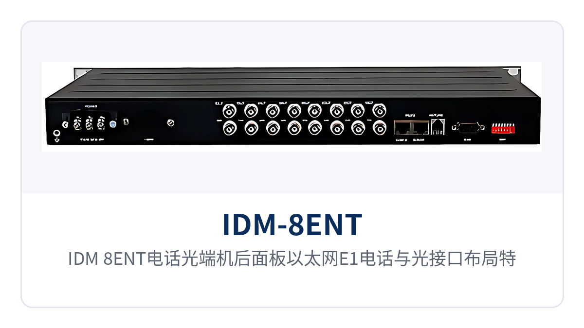
Figure 2: Close-up of the rear panel layout of the Ethernet, E1, telephone, and optical interfaces of the IDM-8ENT telephone optical multiplexer
Why Partition VLANs When 8 Ethernet Groups Share Wire-Speed 100M?
The 8 groups of Ethernet channels sharing wire-speed 100M means that the 8 Ethernet ports share one 100M wire-speed channel, rather than each port occupying 100M. Sharing does not mean mixing: the channel can be partitioned into VLANs as required to separate different service network segments such as dispatch data, video surveillance, and office Internet access, so that broadcasts and failures in one network segment do not spread to another.
For private network sites, isolation affects availability more than bandwidth. Private networks such as electric power, public security, and banking often run production services and management services at the same site simultaneously; if the two types of traffic travel in the same broadcast domain, one infected terminal could drag down the entire link. After services are separated by VLAN, each network segment forwards independently, and both the security boundary and the fault boundary become clear. In government private network optical fiber communication solutions, Ruiguang Jiyuan (Raytrans) often uses such multi-service optical multiplexers as access layer devices, precisely because of the assurance that VLAN isolation provides for private network availability.
Bandwidth allocation should be planned according to actual traffic: the 100M wire-speed channel is shared by the 8 Ethernet ports. When a site accesses multiple video channels simultaneously, it is recommended to partition video into a separate VLAN and calculate peak traffic. Voice channels and E1 do not occupy this bandwidth, so rising Ethernet traffic does not affect telephone calls or E1 dedicated lines, and the planning of the two service types can be done separately.
How to Use E1 Local and Remote Loopback: Remote Fault Determination at Unattended Sites
E1 channels support local loopback and remote loopback, whose purpose is to isolate and locate the fault section on a long link. Loopback means returning the E1 signal along its original path at a specified node; with devices at both ends testing together, it can be determined whether the fault lies in the local device, the optical fiber link, or the opposite-end device.
On-site troubleshooting proceeds from near to far, adding only one variable at each step, peeling away layer by layer from the local device and the optical fiber link to the opposite-end service side, and verifying the entire link segment by segment. All four steps below can be completed remotely from the equipment room side, without first arranging personnel at both ends simultaneously:
- First perform local loopback at the local end; if services return to normal, the local device and wiring are normal, and the fault lies in the optical fiber or the opposite end;
- Then have the opposite end perform remote loopback; if the local end still receives the loopback signal, the optical fiber link is normal, and the fault lies on the opposite-end service side;
- If loopback fails at both ends, return to the optical interface to check link loss and connector connections, and rule out optical fiber breakpoints and connector contamination;
- Combine monitoring and panel alarms to assess line operating conditions, and after relaying the conclusion back to the equipment room, arrange an on-site visit.
What unattended sites save is precisely the on-site visit. Sites such as substations, communication base stations, and business outlets are normally unattended; with local and remote loopback working together with monitoring, the equipment room side can lock the fault to a specific section, decide in advance which spare parts to bring and which section to handle, and resolve the problem in a single on-site visit. This feature also gives the optical multiplexer an advantage in rapid on-site fault determination in military emergency communications vehicle solutions; vehicle-mounted sites are likewise not permanently staffed, and remote loopback can reduce the number of deployments.
Typical Application Scenarios
What the three types of sites—electric power, public security and military, and banking and finance—have in common is mixed services, scattered sites, and high on-site visit costs. The IDM-8ENT consolidates telephone, E1, and Ethernet services into one device, with point-to-point networking: one unit at the central office and one at the remote end, connected by one optical fiber in between. Compared with an 8-channel telephone optical multiplexer that carries only voice channels, sites no longer need an additional device for E1 and data services, and the cabinet and wiring are simplified accordingly; the integration advantage shown in the product showcase is particularly evident at such multi-service sites.
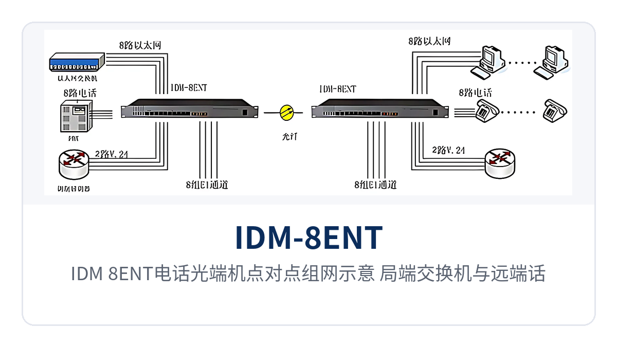
Figure 3: Point-to-point networking schematic of the IDM-8ENT telephone optical multiplexer with central office switch and remote telephone, E1, and Ethernet access
Electric Power Private Network: Substation Telephone and Telecontrol E1 Sent Over the Same Fiber
Between a substation and a dispatch center, both dispatch telephone and E1 dedicated line channels for telecontrol and metering must be provided. The IDM-8ENT connects 8 telephone channels and 8 E1 channels on one device in the station and sends them to the dispatch side over one 155M optical fiber; voice channels and telecontrol data each use their own channels, and fluctuations in data traffic do not affect dispatch telephone. The typical value of such multi-service optical multiplexers in electric power private networks is precisely that one device consolidates voice channels and E1 dedicated lines at the same time.
Select the model according to actual cabinet space and power conditions in the station: the 19-inch 1U chassis occupies only one rack position, and the power supply can be selected between 220V and -48V, so both the DC distribution panel and AC wiring in a communications equipment room can supply power directly, without a separate power distribution panel for the device.
Public Security and Military Private Networks: Duty Post Telephone and Ethernet Backhauled Over One Link
Communications among duty posts, checkpoints, and camps require both voice and an internal network. The IDM-8ENT delivers 8 telephone channels and 8 Ethernet interfaces to the remote end at once; the 8 groups of Ethernet channels separate the duty service network from the office network by VLAN, so the two types of terminals are on the same fiber but different network segments and do not interfere with one another. In military emergency communications vehicle solutions, this capability of consolidating voice and Ethernet in one device is equally applicable, and is especially compact when vehicle-mounted space is limited.
Such sites are mostly unattended, which is where the value of E1 local and remote loopback and line monitoring comes in: when the link is abnormal, the equipment room side first performs a loopback test to lock the section, reducing the number of on-site visits and shortening the communication recovery time at duty posts, with distant sites benefiting especially.
Banking and Financial Dedicated Lines: Centralized Backhaul of Voice Channels and Data at Business Outlets
Business outlets are numerous and scattered, and each outlet needs telephone subscriber line provisioning and data dedicated line uplink. The IDM-8ENT restores 8 telephone channels and 8 Ethernet interfaces at the outlet side; voice channels connect to outlet telephones, and data connects to counter and self-service devices. Multiple services return to the upper-level node over one optical fiber, reducing wiring and rack positions at the outlet side accordingly.
The availability requirements of financial dedicated lines are reflected in fault handling speed: the device provides comprehensive monitoring to assess line operating conditions, and with E1 loopback and two-end fault location, determining which section a fault lies in changes from on-site guesswork to something the equipment room can determine, so spare parts can be prepared before the on-site visit.
Selection and Deployment Points
Selection starts from the service list, determining the number of channels, power supply, optical interface, and VLAN in sequence, so that configuration and quotation do not go back and forth. The five points are listed in on-site order: the first two determine capacity and power supply format, and the last three determine the optical fiber link and network planning:
- Data services: first count the number of voice channels, E1 directions and Ethernet ports, corresponding to 8-channel telephone, 8-channel E1 and 8-group Ethernet respectively;
- Determine power supply: select 220V for AC equipment rooms and -48V for DC communication sites; the two formats are selected at the time of ordering;
- Determine optical interfaces and distance: confirm the optical module type and transmission distance according to the on-site optical cable and link loss; the product documentation does not give fixed values, so provide the link parameters for the manufacturer to calculate;
- Plan VLANs: plan VLAN partitioning of Ethernet channels according to the number of service network segments, separating video from production data;
- Incorporate into inspection: include alarm checking and loopback tests in the daily inspection process, so that unattended sites can reduce unnecessary on-site visits accordingly.
Conclusion
The value of the IDM-8ENT 8-channel telephone and 8-channel E1 optical multiplexer lies in consolidating three types of services into one device and one fiber: 8-channel telephone, 8-channel E1, 8-group Ethernet and 2-channel RS232 are carried over the same fiber, so sites no longer need separate transmission devices for voice and data, and subscriber line provisioning and dedicated line enablement at remote small offices are handled with one unit. For users requiring a government private network optical fiber communication solution, this type of PDH optical multiplexer can interface smoothly with existing PDH systems, and using it as a multi-service optical multiplexer does not waste optical fiber resources either.
For private network sites in electric power, public security and military, and banking sectors, the 8-group Ethernet shares wire-speed 100M and can be isolated by VLAN, keeping multiple services on the same network but in different domains; E1 local and remote loopback plus line monitoring move troubleshooting actions forward to the equipment room. As a three-service same-fiber optical multiplexer, the configuration can be finalized by confirming three items during selection: number of channels, power supply format and optical interface. As an optical multiplexer manufacturer, Raytrans can provide product showcase and technical support for such projects, from selection calculation to deployment and inspection.


