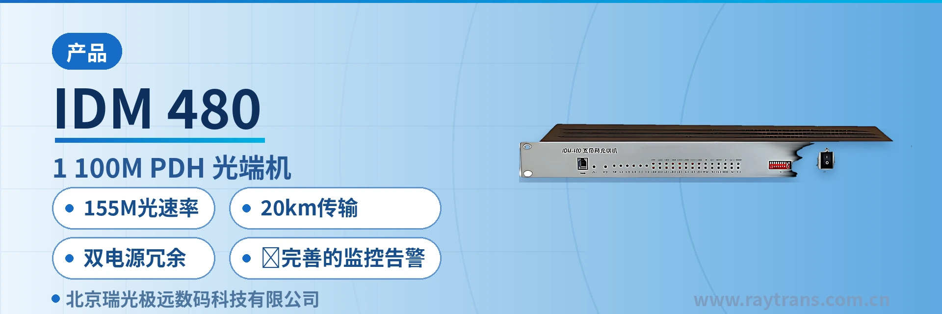
IDM-480 16E1+100M PDH Optical Multiplexer
16E1 and 4 Fast Ethernet channels multiplexed on the same board; one pair of optical fibers saves two devices; panel buttons for status viewing
The 16E1 optical multiplexer is a point-to-point optical transmission device developed with very large-scale integrated circuits. With a compact single-board structure, it implements hybrid multiplexing and optical transmission of 16 E1 channels and 4 100M line-rate Ethernet data channels, combining the functions of a PDH optical multiplexer and a 100M Ethernet media converter. The IDM-480 provides a network management interface and a user auxiliary channel, with comprehensive alarm monitoring, high integration, low power consumption, stable performance, and ease of use. The IDM-480 broadband network optical multiplexer is a product that integrates a traditional carrier-class E1 optical multiplexer with an Ethernet media converter.
What Kind of Equipment Is the IDM-480 16E1 Ethernet Hybrid Multiplexing Optical Multiplexer
The IDM-480 16E1 Ethernet hybrid multiplexing optical multiplexer is a point-to-point optical transmission device developed by Beijing Ruiguang Jiyuan Digital Technology Co., Ltd. (Raytrans). It multiplexes 16 E1 channels and 4 channels of 100M Ethernet service onto a single optical fiber for transmission. The device uses a simple single-board architecture to multiplex and demultiplex both E1 and Ethernet services, combining the functions of a PDH optical multiplexer and a 100M Ethernet media converter; it is a typical PDH optical multiplexer product.
Conventionally, a site would need one PDH optical multiplexer for the E1 leased line and a separate Fast Ethernet media converter for Ethernet, with each set of equipment occupying its own rack position and a pair of optical fibers. The IDM-480 consolidates both functions into a single 1U chassis, with one pair of optical fibers handling all backhaul, so rack space, optical cable cores, and the variety of spare parts are all counted on the basis of one device. For selection scenarios that require a product showcase, this integrated design also makes the device's capabilities easy to present intuitively.
Key specifications at a glance: 16E1 + 4×100M · 155M optical rate · 20 km transmission · dual power supply redundancy · single-board 1U chassis · overall power consumption <15 W
Power is supplied in either ~220 V AC or -48 V DC format, and the two can also serve as redundancy for each other, adapting to sites where AC equipment rooms and communications DC equipment rooms coexist. The unit features a single-board design in a 19-inch 1U chassis that can be installed in a standard cabinet or placed nearby in box form; the operating temperature is 0℃~45℃, and the overall power consumption is below 15 W.
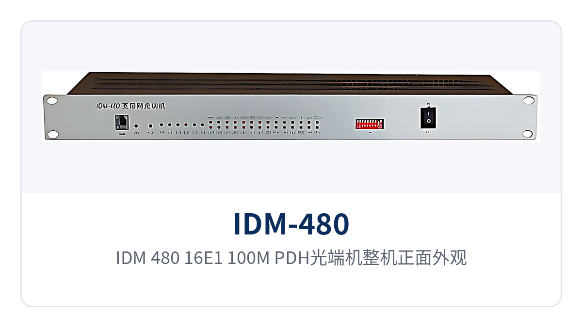
Figure 1: Front appearance of the IDM-480 16E1+100M PDH optical multiplexer, with panel alarm indicator LEDs and power supply unit layout
How a Single Board Carries 16E1 and 4 Fast Ethernet Channels Simultaneously
The 16 E1 channels and 4 Fast Ethernet channels are multiplexed on the same board. The E1 side is transparently transmitted in accordance with ITU-T G.703, and the Ethernet side accesses at the auto-negotiated interface rate; once the two types of service enter the device, neither changes the other's frame structure or time slot content. The following table lists the device's capabilities by function; during selection, check each row against the site service list.
Features
| Function | Description |
|---|---|
| 16-channel E1 transparent transmission | Provides 16 E1 channels with a bit rate of 2.048 Mbit/s and HDB3 line coding; after entering the device they are only multiplexed, without changing the original time slot content |
| 4-channel Fast Ethernet | Provides 4 adaptive 10M/100M Ethernet interfaces with auto-negotiation support, operating in full-duplex or half-duplex mode |
| E1 and Ethernet hybrid multiplexing | Multiplexes 16 E1 channels and 4 Ethernet services onto one 155M optical line, restoring them at the opposite end after point-to-point transmission |
| Alarm monitoring | Provides alarms for loss of optical signal, out of frame (OOF) of the optical signal, 1E-3 bit errors, 1E-6 bit errors, and loss of signal on each E1 tributary, and indicates Ethernet interface status |
| Remote-end alarm viewing | Through panel buttons, the local indicator LEDs display the alarm status of the opposite end, making it easy to determine whether a failure lies at the local end or the opposite end |
| E1 tributary remote loopback | Supports E1 tributary remote loopback for per-channel testing of channel and line quality |
| Network management and auxiliary channel | Provides a network management interface and a user auxiliary channel, carrying O&M data separately from service channels |
| Dual power supply redundancy | ~220 V AC or -48 V DC selectable, with the two power feeds able to serve as redundancy for each other |
The Ethernet ports support 10M/100M adaptation and auto-negotiation and can operate in full-duplex or half-duplex mode; when connecting the device to a PC, use a crossover network cable, and when connecting to a switch, use a straight-through cable. E1 interfaces are connected as 75 Ω unbalanced or 120 Ω balanced, the impedance at both ends must be consistent, and the receive/transmit directions must be paired according to the markings at the opposite end. As a multi-service optical multiplexer, the device carries both E1 and Ethernet services on the same platform, making it suitable for scenarios requiring multi-service hybrid transmission, such as government private network optical fiber communication solutions and military emergency communications vehicle solutions.
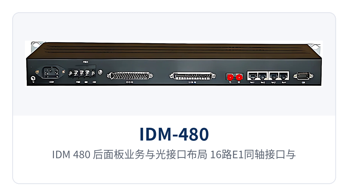
Figure 2: Rear panel service and optical interface layout of the IDM-480, with 16 E1 coaxial interfaces and 4 Fast Ethernet RJ45 connectors
How to Check the Optical Port, E1 Port, and Ethernet Interface Parameters
The parameters of the optical interface, E1 interface, and Ethernet interface determine what cables the device can connect, how far it can transmit, and how much link margin is available. The values in the following tables are taken from the product documentation; use them for engineering calculations, and base the optical power budget and site power supply capacity on the specifications in the tables. For items marked as optional or requiring special notes, confirm the specific configuration with the commercial team when ordering.
Optical Interface and E1 Interface Parameters
| Item | Parameter/Specification | Description/Applicable Conditions |
|---|---|---|
| Optical fiber rate | 155 Mb/s±50 ppm | Optical line multiplexing bandwidth basis |
| Wavelength | 1310 nm | Optical modules at both ends matched in pairs |
| Transmit optical power | -2~-11 dBm | Transmit-side specification, calculated per link budget |
| Receiver sensitivity | Better than -36 dBm | Receive-side specification, determines the usable loss budget |
| Receive dynamic range | 34 dB | Optical reception works normally as long as link attenuation is within this range |
| Optical interface form | FC/SC optional | Selected according to on-site patch cords and fiber adapters |
| Transmission distance | Not less than 20 km by default | Distances over 40 km or 60 km require special notes at ordering |
| Number of E1 channels | 16 | A single unit can connect 16 E1 services |
| E1 bit rate | 2.048 Mbit/s±50 ppm | Rate of a single E1 channel |
| E1 line coding | HDB3 | Complies with ITU-T G.703 |
| E1 jitter specifications | Complies with ITU-T G.703, G.823, G.742 | Jitter tolerance, transfer characteristics, and output jitter are assessed per the above recommendations |
| E1 impedance | 75 Ω unbalanced/120 Ω balanced | Impedance at both ends must be consistent |
Ethernet, Power Supply, and Environmental Parameters
| Item | Parameter/Specification | Description/Applicable Conditions |
|---|---|---|
| Ethernet interface | 4 adaptive 10M/100M RJ45 connectors | Supports auto-negotiation; full-duplex/half-duplex configurable |
| Ethernet standard | IEEE 802.3 10BaseT, 100Base-TX | Negotiates with existing switches at the original rate |
| Network cable selection | Crossover cable for PC connection, straight-through cable for switch connection | Selected according to the type of opposite-end device |
| AC power supply | 220 V (165-260 V), 50 Hz | AC equipment room or mains power conditions |
| DC power supply | -48 V, 1 A | Communications DC equipment room conditions |
| Power supply mode | ~220 V or -48 V selectable, able to serve as redundancy for each other | The two power feeds are taken from different circuit breakers |
| Operating temperature | 0℃~45℃ | Equipment room and non-constant-temperature cabinet environments |
| Operating humidity | 90% (non-condensing) | Indoor installation conditions |
| Storage temperature | -20~70℃ | Storage and transportation environment |
| Overall power consumption | <15 W | Heat dissipation and power supply capacity pressure during long-term operation are controllable |
| Device specifications | 19-inch 1U/box type | Cabinet installation or nearby placement |
How to Calculate the 155M Optical Rate and 20 km Transmission Capability
The 155 Mbps optical line rate is the multiplexing bandwidth basis of the IDM-480. The 16 E1 channels total approximately 32.768 Mbit/s, and the 4 Ethernet channels access at the auto-negotiated interface rate; both types of service share this 155M optical line. E1 channels occupy bandwidth by time slot, while Ethernet services are allocated bandwidth according to actual traffic. When planning site bandwidth, include the traffic of both types of service together rather than calculating on the basis of only one of them. This bandwidth allocation method of hybrid E1 and Ethernet multiplexing is a typical application of PDH optical multiplexers in multi-service scenarios.
The default transmission distance basis is not less than 20 km, calculated with standard-configuration optical modules and conventional optical cable attenuation. When station spacing exceeds 40 km or 60 km, a special note is required at ordering, and the optical multiplexer manufacturer selects long-distance optical modules of the corresponding distance according to link length, replacing them in pairs at both ends. As a media converter manufacturer and optical multiplexer manufacturer, Raytrans can provide configuration recommendations corresponding to project link conditions.
Whether a link can remain stable over the long term is calculated from the difference between transmit optical power and receiver sensitivity, not merely from the nominal distance. With transmit optical power of -2~-11 dBm, receiver sensitivity better than -36 dBm, and a receive dynamic range of 34 dB, after deducting splice points, fiber adapters, and per-kilometer optical cable attenuation, the remaining margin is the engineering margin of the link.
How E1 Alarms and Remote Loopback Support On-Site Troubleshooting
The alarm information of the E1 channels and the optical path is the direct basis for determining the direction of a failure. The IDM-480 consolidates optical path and tributary status onto panel indicator LEDs, so on-duty personnel in the equipment room can see whether the problem lies on the optical path side or the E1 side. Alarms cover the following, with panel indicator LEDs showing the specific status:
- Loss of optical signal on the line;
- Out of frame (OOF) of the optical signal;
- 1E-3 bit error alarm and 1E-6 bit error alarm;
- Detection of loss of E1 input signal;
- Loss of signal on each E1 tributary;
- Ethernet interface status indication.
In addition to reporting local alarm status, panel buttons allow the local indicator LEDs to display the alarm status of the opposite end. When a remote site is unattended, maintenance personnel at the central end can distinguish whether the local optical reception is abnormal or the opposite-end device is abnormal. The device can also output alarm information for connection to the existing alarm collection system in the equipment room.
E1 tributary remote loopback is used to test channel quality channel by channel: after looping back a given E1 channel at the opposite end, send a test signal to that channel from the local end and observe bit errors and alarms, narrowing the fault scope to a single tributary or a single cable segment. Schedule loopback tests during idle service periods, and restore service only after recording the results for each channel.
Typical Application Scenarios
The IDM-480 is mainly deployed point-to-point: one unit at the service site and one in the central equipment room, with the two ends directly connected by optical fiber; E1 channels and Ethernet services are restored at the central side and then connected back to existing transmission equipment and switches. The three target industries each have their own emphasis; when a site is expanded, only interfaces need to be added, without laying new optical cables.
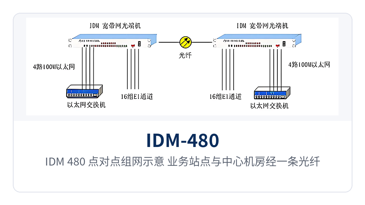
Figure 3: Point-to-point networking diagram of the IDM-480, with the service site and central equipment room backhauling E1 and Ethernet services over one optical fiber
Electric power private network: substation telecontrol E1 and production network backhauled over the same cable
Substations, distribution stations, and new energy stations simultaneously run dispatch automation, relay protection signals, and video surveillance; sites are mostly unattended, with limited equipment room space and power supply conditions. The IDM-480 consolidates the E1 channels for telecontrol and protection information and the Ethernet services for the production network and video surveillance into one 1U device, so the station no longer needs a separate optical multiplexer for each type of service.
The two power supply formats, AC 220 V and DC -48 V, are selectable and serve as redundancy for each other, corresponding to the two conditions of AC mains power and communications DC power in the station; when one power feed fails, the other continues to carry the load, so power supply at unattended sites does not depend on a single feed. Panel alarms and remote-end alarm viewing let O&M personnel determine link status at the centralized control station.
Rail transit: E1 channel and surveillance network access at stations and section equipment rooms
Between stations and section equipment rooms of railways and urban rail transit, train dispatching telephone, signaling system E1 channels, and video surveillance data need to be transmitted, with station spacing of several kilometers and limited equipment room conditions. The IDM-480 is deployed point by point according to site distribution; each station accesses E1 and Ethernet services nearby, and they are backhauled over trunk optical fibers to the station communications equipment room or control center.
The 16 E1 channels suit the multiple 2M channels of the signaling and communications disciplines, and the 4 Fast Ethernet ports carry the surveillance and office networks. The standard 20 km transmission covers common section distances; for longer sections, select long-distance optical modules per the ordering notes, without changing the device itself or the cabinet layout.
Military and government private networks: dedicated line access at command posts and duty points
A command post, a duty point, and a higher-level authority often need both E1 leased lines and an internal Ethernet at the same time, while the cable route is fixed and the number of available fiber cores is limited. The IDM-480 carries 16 E1 channels and 4 Fast Ethernet channels over a single optical fiber, so the narrowband leased lines and the data network share the same pair of optical fibers, and the laying and fiber leasing costs are calculated per link.
The device provides a network management interface and user auxiliary channels, with O&M data and service channels carried separately. The front panel alarm and opposite-end alarm viewing functions let on-duty personnel determine link status without additional instruments, so failure reporting and handling connect more quickly. Equipment rooms at duty points are often managed part-time by duty personnel, so whether the alarm indication is straightforward and readable directly affects the response speed.
Conclusion
As a 16E1 Ethernet hybrid multiplexing optical multiplexer, the IDM-480 packs 16 E1 channels and 4 Fast Ethernet channels into a single board, with an optical line rate of 155Mbps, a default transmission distance of no less than 20km, ~220V and -48V dual power supplies, comprehensive alarms, and overall power consumption below 15W. One unit replaces a PDH optical multiplexer plus a media converter, saving both rack and optical cable resources.
During selection, first count the number of E1 channels and Ethernet port requirements at the site, then determine the optical module distance grade according to the link length, and check the power supply format and cabinet space. The IDM-480 PDH optical multiplexer is intended for site access in electric power private networks, rail transit, and military and government private networks, and services can be enabled once the two ends are configured as a pair.