
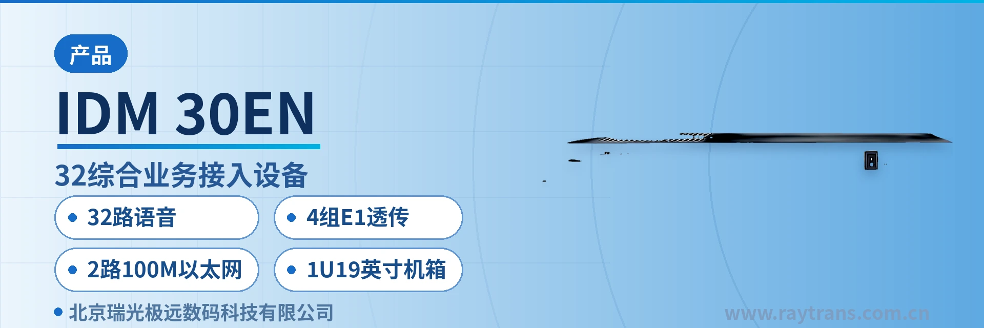
IDM-30EN-32 Integrated Service Access Device
32 Voice Channels, 4 Groups of E1 Transparent Transmission, 2 Channels of 100M Ethernet, One Fiber Saves Two Devices
The IDM-30EN-32 Integrated Service Optical Multiplexer uses optical fiber as the transmission medium and, by means of standard optical fiber or E1 transmission channels (ITU-T G.703 standard) and the PCM30/32 format, converts the telephone service signals or data signals to be transmitted
A 32-channel voice 1U rack-mounted optical multiplexer is an optical fiber multiplexing terminal that provides 32 voice channels, 4 groups of E1 transparent transmission interfaces, and 2 line-rate 100M Ethernet ports within a single 19-inch 1U chassis, sending all three service types back to the peer equipment room over one optical fiber. The IDM-30EN-32 integrated service access device belongs to this category and is listed under telephone optical multiplexers on the official website.
The IDM-30EN-32 uses optical fiber as its transmission medium and can also carry services over existing standard E1 channels (G.703) on site, converting telephone signals and data signals into optical signals for transmission to the remote end using the PCM30/32 format. The IDM-30EN-32 is developed by Beijing Raytrans and targets multi-service access at the site side for electric power private networks, public security private networks, and bank leased lines.
Private network endpoint sites often need to run dispatch telephones, E1 leased lines, and a service-network Ethernet connection at the same time, which used to require two or three devices stacked in one cabinet. The IDM-30EN-32 consolidates the three interface types into a single 19-inch 1U chassis, providing 32 voice channels, 4 groups of E1 transparent transmission, and 2 line-rate 100M Ethernet ports per unit, carrying all three networks over one fiber and reducing both cabinet space and fiber core usage.
With receiver sensitivity better than -34 dBm and a receive dynamic range of 34 dBm, the device still receives stably over weak-light long-distance links. A wide dynamic range means received optical power can be judged correctly across a large interval; for remote stations with relatively high line loss, there is no need to rush into adding repeaters after power-on—first verify the received optical power margin with an optical power meter, then decide the configuration.
Key Specifications at a Glance: 32 voice channels · 4 groups of E1 transparent transmission · 2 100M Ethernet ports · 1U 19-inch chassis · 155Mbps/1310nm optical port · PCM30/32 format · sensitivity better than -34 dBm
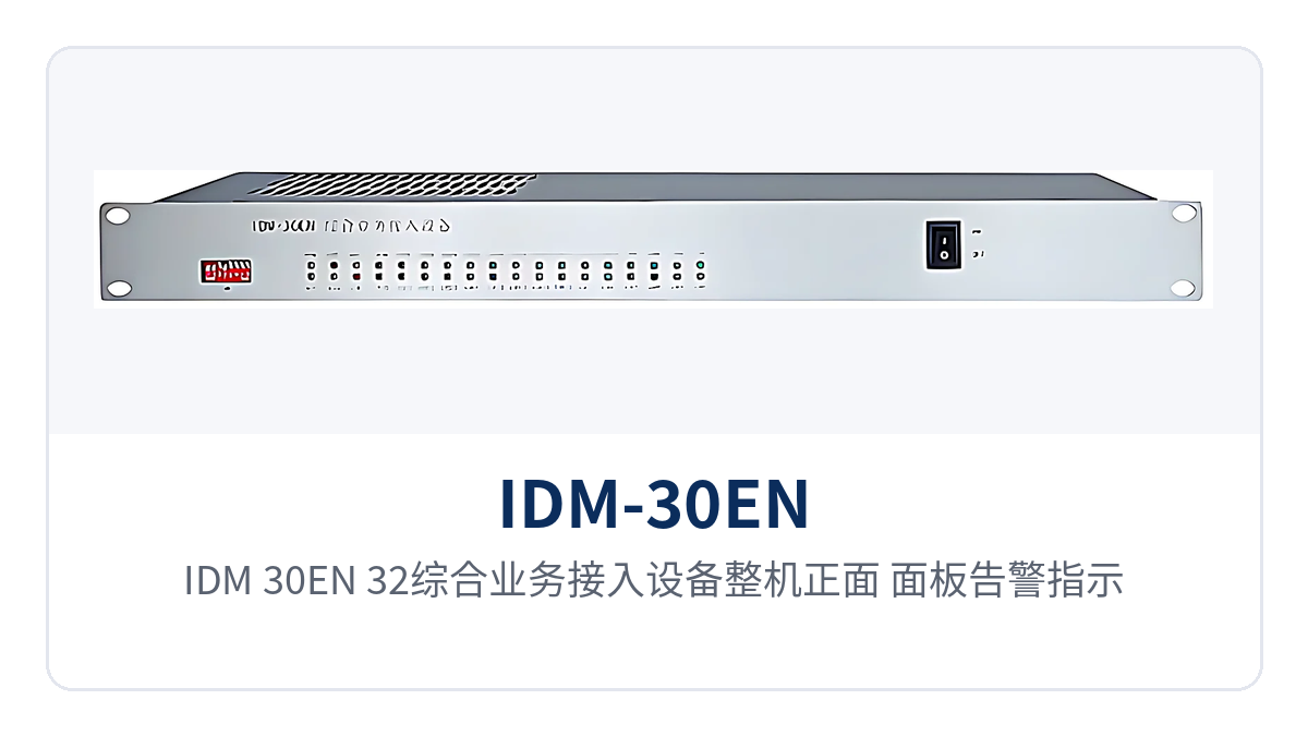
Figure 1: Front view of the IDM-30EN-32 integrated service access device, showing panel alarm indicator LEDs and the layout of FXO/FXS voice channel cards, E1, and FC optical ports
What is a 32-channel voice 1U rack-mounted optical multiplexer?
The core role of this product showcase is to merge narrowband services and IP services at the site side onto a single optical path. The IDM-30EN-32 provides standard 32-channel voice service, 4 E1 interfaces supporting transparent transmission, and 2 line-rate 100M Ethernet interfaces in a single 19-inch 1U chassis; the remote device restores the corresponding FXO/FXS voice channels and RJ-45 ports after receiving the optical signal. As a typical telephone optical multiplexer, it concentrates voice and data services on one optical multiplexer for multiplexing and transmission.
When optical cable already exists on site, two devices can form a 155M optical channel point-to-point, bringing the remote site's telephone and network services back to the central equipment room in one pass. The device uses the PCM30/32 format, organizing 32 64K voice channels into the optical channel by time slot, consistent with the time slot conventions of existing PCM links, so the peer end does not need to re-plan time slots during cutover. This multi-service optical multiplexer design approach is tailored precisely for government private network optical fiber communication solutions and electric power private network multi-service access scenarios.
The function control switches and alarm indications on the panel are the direct basis for on-site troubleshooting; abnormalities such as optical path interruption and E1 loss of frame alignment are all indicated on the device. The clock can be set as master clock or user clock according to the networking topology—one end of a point-to-point link provides the master clock and the other follows, giving a clear synchronization relationship.
What service interfaces do 32 voice channels and 4 groups of E1 transparent transmission provide?
The user interfaces of the IDM-30EN-32 fall into three categories—voice, E1, and Ethernet—each carrying different services. The functional positioning and applicable occasions of the three interface types are listed in the table below; during selection, compare them item by item against the site's existing services, as the configurations do not encroach on one another.
| Function | Description |
|---|---|
| 32-channel voice service | Provides standard 32-channel voice service using the PCM30/32 format, carrying telephone voice channels over 64K time slots |
| 4 groups of E1 interface transparent transmission | The 4 E1 interfaces support transparent transmission mode, fully comply with ITU-T G.703, and can reuse the 2M channels of existing PCM and SDH/PDH networks |
| 2 groups of line-rate 100M Ethernet | Provides 2 line-rate 100M Ethernet interfaces with VLAN partitioning, carrying office, surveillance, and production data |
| 64K subscriber interface | Provides ordinary telephone cards with caller ID (FXO, FXS), landing 64K time slots as physical circuits that can connect telephones |
| Clock mode setting | Master clock and user clock can be set to suit synchronization requirements in different networking environments such as point-to-point and chain |
| Function control and alarms | Complete function control switches and alarm indication for easy commissioning and routine maintenance |
| 19-inch 1U chassis | Uses a standard 19-inch 1U chassis for easy rack installation in cabinets or communication racks in private network equipment rooms |
Service landing relies on 64K time slots: the exchange side connects to FXO cards and the user side to FXS cards, restoring 32 time slots into physical voice channels. The 4 E1 interfaces connect to the 2M tributaries of existing PCM or SDH/PDH networks, and the 2 Ethernet ports connect IP services to the site data network. The three service types are multiplexed within the same multi-service optical multiplexer, so the site side only needs to lay fiber once to activate all of them simultaneously—particularly suited to the unified multi-service access requirements of government private network optical fiber communication solutions.
How are 32 voice channels and 4 groups of E1 transmitted simultaneously?
The answer to how 4 groups of E1 are transmitted simultaneously is time division multiplexing: voice channels and E1 services are first arranged into PCM30/32 primary group frames by time slot, then modulated together with Ethernet services onto a 155M optical signal. The 32 64K voice channels of the IDM-30EN-32 occupy fixed time slots, the 4 groups of E1 each carry a 2048 kbit/s primary group in transparent transmission mode, and Ethernet services are transmitted along the allocated bandwidth within the optical channel. This mechanism follows the same primary group multiplexing principle as PDH optical multiplexers, ensuring compatible interworking with traditional PDH optical multiplexer networks.
The receive side demultiplexes layer by layer, restoring services to FXO/FXS voice channels, E1 interfaces, and RJ-45 ports. Voice uses fixed time slots with controllable delay and jitter; E1 transparent transmission does not alter the original frame structure, so peer devices usually need no time slot reconfiguration; Ethernet is partitioned by VLAN and shares the same fiber core with telephone channels.
What are the technical specifications of the 32-channel voice 1U rack-mounted optical multiplexer?
The key parameters of the optical interface, E1 interfaces, voice channel interfaces, and Ethernet interfaces are listed in the table below; link budget and device configuration are calculated on this basis. The values in the table are taken from product technical documentation; on-site measured values are subject to readings from an optical power meter and test instruments, and power supply and power consumption are subject to the accompanying documentation.
| Item | Parameter/Specification | Description/Applicable Conditions |
|---|---|---|
| Optical interface type | FC (SC and others can be customized) | Selected according to on-site fiber cores and engineering practice |
| Optical fiber rate | 155Mbps±50ppm | Corresponds to the 155M optical transmission platform, shared by voice and Ethernet services |
| Wavelength | 1310nm | Typical single-mode operating wavelength |
| Transmit optical power | -4 to -12 dBm | Typical single-mode value; subject to actual measurement with an optical power meter |
| Receiver sensitivity | Better than -34 dBm | Can be used to calculate the link loss budget and available distance |
| Receive dynamic range | 34 dBm | Optical path budget basis paired with receiver sensitivity |
| E1 standard protocol | Supports ITU-T G.703 | Fully complies with G.703 recommendation |
| E1 bit rate | 2048 kbit/s±50ppm | Primary group bit rate |
| E1 line code | HDB3 | Keep consistent with the peer device's line code configuration |
| E1 impedance | 75 Ω (unbalanced)/120 Ω (balanced) | An external impedance converter is required when using 120 Ω balanced interfaces |
| E1 frame structure/signaling | PCM30/32; channel-associated signaling | Services are transmitted as they are, without changing time slot content |
| Ethernet interface | RJ-45, 10/100M half/full duplex | Port mode adaptive at 10/100 Mbps |
| Ethernet standard protocol | Complies with IEEE-802.3u | Negotiated according to port capabilities when interworking with switches and routers |
| FXO/FXS audio range | 300 Hz to 3400 Hz | Telephone voice channel bandwidth |
| FXO/FXS impedance | Three-element complex impedance 200 Ω+560 Ω//0.1 μF | AC and DC characteristics basis for voice channel interfaces |
| FXO/FXS compression | ITU G.711 A-law | Voice encoded at 64K using A-law |
| FXO/FXS loop current | 25 mA per channel | Feed loop current per telephone |
| Power supply mode | Not yet recorded in the knowledge base | Subject to the accompanying product documentation and commercial confirmation |
| Overall power consumption | Not yet recorded in the knowledge base | Subject to the accompanying product documentation and commercial confirmation |
| Operating temperature/humidity | Not yet recorded in the knowledge base | Subject to the accompanying product documentation and commercial confirmation |
The optical interface parameters directly determine how long a link can span: with transmit optical power of -4 to -12 dBm, receiver sensitivity better than -34 dBm, and a receive dynamic range of 34 dBm, subtracting sensitivity from transmit power and then deducting optical cable and connector loss gives the available margin. Measure the received optical power at the peer end first, then decide whether to add repeaters or replace optical modules. As a mature product from a professional optical multiplexer manufacturer, Raytrans has rigorously tested every parameter of this model, providing reliable data support for electric power private network multi-service access.
How to wire a telephone optical multiplexer?
Wiring a telephone optical multiplexer can proceed in six steps: optical path, E1, telephone, Ethernet, clock, and rack installation. The steps follow the signal flow—get the optical path through first, then work on service interfaces, which means less rework; verify each step before moving to the next, so that service failures can be quickly traced to the specific interface.
- Optical path: connect the optical interface (FC; SC and others can be customized) to the ODF via pigtails; two devices form a 155M optical channel point-to-point; verify transmit optical power and receive margin with an optical power meter;
- E1: for the 4 E1 interfaces, choose 75 Ω unbalanced (coaxial) or 120 Ω balanced wiring according to the peer interface; an external impedance converter is required when using 120 Ω balanced interfaces; keep the line code and frame structure consistent with HDB3 and PCM30/32;
- Telephone: connect the exchange side to FXO cards and the user side to FXS cards; voice channels have an audio range of 300 Hz to 3400 Hz, ITU G.711 A-law compression, and a loop current of 25 mA per channel, and can directly interconnect with existing telephone systems;
- Ethernet: connect the 2 RJ-45 interfaces to switches or routers; ports are adaptive at 10/100 Mbps; configure VLANs according to service planning;
- Clock: set the master clock and user clock according to the networking topology—one end of a point-to-point link is set as master clock and the other follows;
- Rack installation and alarms: install the 19-inch 1U chassis in a standard cabinet or communication rack and secure it; verify the panel function control switches and alarm indications, then enable services item by item once normal.
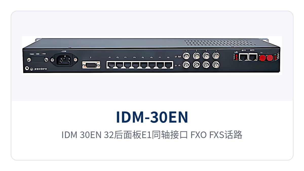
Figure 2: Wiring diagram of the IDM-30EN-32 rear panel E1 coaxial interfaces, FXO/FXS voice channel card interfaces, Ethernet RJ-45 ports, and power supply terminals
After wiring is complete, verify the optical path and E1 channels first, then enable voice channels and Ethernet services one by one. Raytrans can provide wiring guidance and commissioning support for private network scenarios such as electric power, public security, and banking, interworking with existing switches and transmission devices on site, delivering end-to-end assurance from product showcase to on-site implementation for government private network optical fiber communication solutions and electric power private network multi-service access.
How do the 19-inch 1U chassis and alarm indications help field sites?
The installation convenience brought by the 19-inch 1U chassis is the practical value of this telephone optical multiplexer at field sites. The chassis is 1U high and can be rack-mounted together with the site's communication rack or standard cabinet, occupying little cabinet space; the panel concentrates function control switches and alarm indications, so O&M personnel can judge link status standing in front of the cabinet.
Selectable master/user clocks let the device adapt to different networking topologies such as point-to-point and chain. Field sites are often unattended; a clock mismatch can cause E1 slips and voice channel noise, so confirming the master-slave relationship against the networking diagram during commissioning saves more effort than troubleshooting site by site afterward.
The device's optical power adaptation range also affects the maintenance workload at field sites. With receiver sensitivity better than -34dBm and a dynamic range of 34dBm, there is still margin for loss changes caused by line aging or additional splice points, and weak-light long-distance links remain stable.
Typical Applications of IDM-30EN-32 in Private Networks
The common features of the three types of private networks—electric power, public security, and banking—are distributed sites and low service volume per site but a full range of service types, which exactly matches the combination of three types of interfaces on one multi-service optical multiplexer. The three scenarios below explain how to deploy equipment on the site side and how services return to the central equipment room.
Electric Power Private Network: Dispatch Telephone and In-Station Data Backhaul over One Fiber
Between a substation and the dispatch center, narrowband services such as dispatch telephone and telecontrol data must be transmitted, as well as Ethernet data for in-station office and monitoring. One IDM-30EN-32 is deployed at each site, and a single optical fiber carries 32 voice channels and 2-channel Fast Ethernet back to the dispatch equipment room together. Voice channels are encoded in A-law per ITU G.711 with a loop current of 25mA per channel, and can be directly connected to dispatch and administrative voice channels.
The 4 E1 interfaces are transparently transmitted per ITU-T G.703. When interfacing with existing PCM or SDH/PDH equipment, time slot configuration usually requires no adjustment, and only a pair of fiber cores is occupied between stations. The 19-inch 1U chassis is suitable for rack mounting in a standard cabinet in an electric power equipment room and is installed together with the in-station communication panel, occupying one less tray.
Public Security Private Network: Multi-Service Access at Police Stations and Command Centers in One Step
Between police stations, duty posts, and the command center, official telephone, office network, and video backhaul channels are all required. IDM-30EN-32 multiplexes 32 voice channels and 2 groups of wire-speed 100M Ethernet into one optical fiber. Ethernet is carried separately for the office network and the video surveillance network through VLAN partitioning, so the two types of services do not affect each other.
The 4 E1 transparent transmission interfaces can connect to the 2M channels of existing PCM or SDH transmission networks, so capacity expansion on the existing private network does not require changing the backbone time slot planning. The panel alarm indication is especially useful when the duty post is unattended; the central side locates the faulty site based on alarms and can resolve it with a single site visit.
Banking Dedicated Line: Voice and Service Data over the Same Fiber at Bank Branches
Between a bank branch and the branch equipment room, counter telephone and service data usually need to be backhauled simultaneously, while equipment room space and optical cable resources are both tight. One 19-inch 1U device combines 32 voice channels and 2-channel wire-speed 100M Ethernet onto the same optical fiber. Counter voice channels are encoded in A-law per ITU G.711 with a loop current of 25mA per channel.
Service data is carried over RJ45 Ethernet ports and can be separated from voice channels through VLAN partitioning; the 4 E1 transparent transmission interfaces are compatible with the existing PCM and SDH channels at the branch. One device replaces multiple stacked units, saving fiber cores and cabinet space during branch upgrades, and reducing construction and routine maintenance workload accordingly.
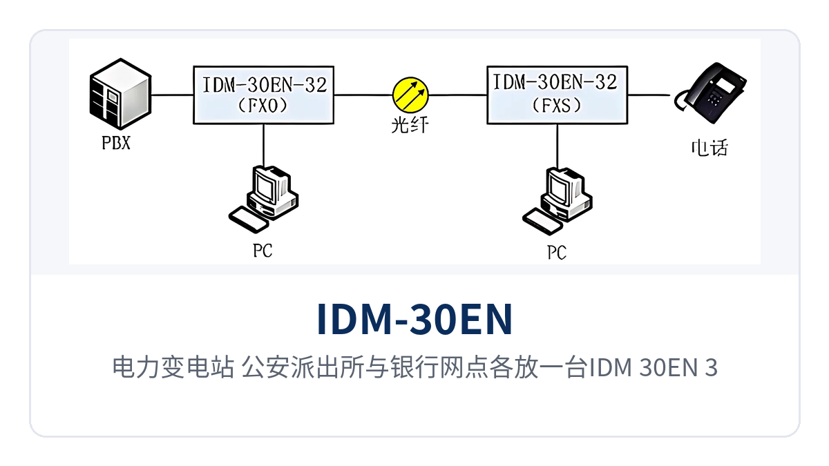
Figure 3: Networking topology in which one IDM-30EN-32 is deployed at each electric power substation, police station, and bank branch, and services are backhauled point-to-point over optical fiber to the central equipment room for unified aggregation
Correspondence Between Differentiated Capabilities and Private Network Value
The three capabilities correspond to access density, optical path margin, and chassis maintenance, and are listed item by item in the table below. The left column gives the capability statement on the product side, and the right column maps it to the actual benefits on the site side. During selection, compare and trade off item by item according to the service volume and line conditions of the site, and configuration differences are clear at a glance.
| Differentiated Selling Point | Specific Capability | Value to Private Network Customers |
|---|---|---|
| One device simultaneously carries 32 voice channels, 4 E1 transparent transmission interfaces, and 2-channel wire-speed 100M Ethernet, with three types of services over one fiber | Provides 32 voice interfaces, 4 E1 transparent transmission interfaces, and 2 groups of wire-speed 100M Ethernet interfaces within one optical fiber channel | Voice, E1, and Ethernet services are backhauled at the site side in one step, eliminating the need for a separate device for telephone and network, and reducing equipment stacking and fiber core usage |
| Optical receiver sensitivity better than -34dBm and a dynamic range of 34dBm, remaining stable on weak-light long-distance links | 155M/1310nm FC optical port, transmit optical power -4 to -12dBm, receive dynamic range 34dBm | Remote stations with relatively high line loss can still be enabled; the link budget basis is clear, providing a reference for both preliminary design and acceptance |
| 19-inch 1U chassis with complete alarm indications and selectable master/user clock, easy to install and maintain at field sites | 19-inch 1U standard chassis, front panel with function control switch and alarm indication, clock configurable as master clock or user clock | Rack-mounted with the communication panel, occupying little cabinet space; unattended sites locate faults by panel alarms, with low routine maintenance workload |
Conclusion
The 32-channel voice 1U rack-mounted optical multiplexer (IDM-30EN-32 integrated service access device) packs 32 voice channels, 4 E1 transparent transmission interfaces, and 2-channel wire-speed 100M Ethernet into one 19-inch 1U chassis, and the site side backhauls the three types of services to the center over one optical fiber in one step.
With receiver sensitivity better than -34dBm and a receive dynamic range of 34dBm, weak-light long-distance links remain stable; together with panel alarm indications and selectable master/user clock, installation and maintenance at field sites are both hassle-free. For selection and configuration of electric power, public security, and banking private networks, please confirm commercially with professional optical multiplexer manufacturers such as Raytrans.


