
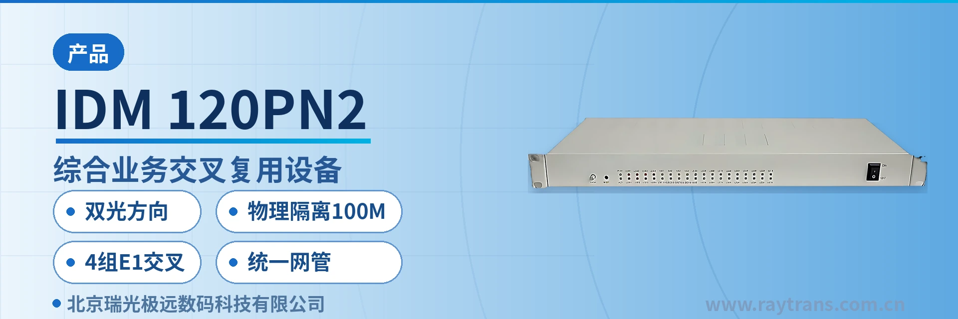
IDM-120PN2 Integrated Service Cross-Connect Multiplexing Equipment
Dual optical direction chain networking, 4 groups of E1 full time-slot cross-connection, dual-channel physically isolated Ethernet
The IDM-120PN2 multi-service optical multiplexer is based on the IDM-120P and provides 2 groups of high-speed optical interfaces in two optical directions, 4 groups of E1 transparent transmission interfaces, and 2 groups of wire-speed 100M Ethernet interfaces that can be physically isolated, facilitating the formation of optical chain networks and saving line resources
The IDM-120PN2 Integrated Service Cross-Connect Multiplexing Equipment is a dual-optical-direction cross-connect multiplexing optical multiplexer developed by Beijing Ruiguang Jiyuan Digital Technology Co., Ltd. Based on the IDM-120P platform, it combines 2 groups of high-speed optical interfaces in two optical directions, 4 groups of E1 transparent transmission interfaces, and 2 groups of wire-speed 100M Ethernet interfaces that can be physically isolated into a single device. As a multi-service optical multiplexer, it facilitates the formation of optical chain networks and saves line resources. As a professional optical multiplexer manufacturer, Raytrans offers this product for the product showcase requirements of chain networking in government private network optical fiber communication solutions.
Key Specifications at a Glance: 2 groups of high-speed optical interfaces in two optical directions · 4 groups of E1 transparent transmission · 2 groups of physically isolated wire-speed 100M Ethernet · 4 groups of E1 full time-slot cross-connection · asynchronous RS232/RS485 · multiple clock modes · unified network management and alarms
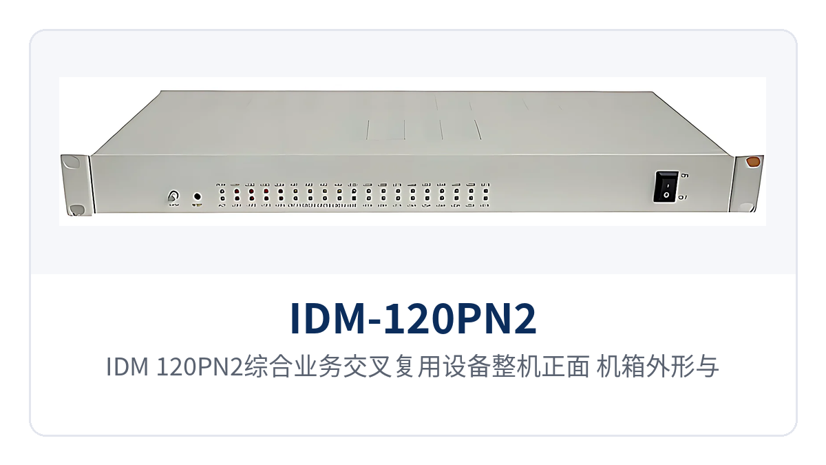
Figure 1: Front view of the IDM-120PN2 Integrated Service Cross-Connect Multiplexing Equipment, showing the enclosure appearance, panel indicator LEDs, and alarm indications
How Does a Dual-Optical-Direction Cross-Connect Multiplexing Optical Multiplexer Form a Chain Network
Each site of the device has two optical channels, which is the key difference from a single-optical-port optical multiplexer: the two optical directions can be connected to the previous station and the next station respectively, so multiple sites are connected in series into an optical chain, and services are passed station by station along the chain. An intermediate site on the chain is both the service access point of its own node and the connection between the two adjacent optical path segments, and the central end can collect the services of the entire chain at one end. As a mature product from a professional optical multiplexer manufacturer, this Raytrans optical multiplexer shows good adaptability in chain networking scenarios.
- Chain networking: the two optical directions of an intermediate site connect to the previous and next stations respectively, and the entire optical chain only needs a pair of optical fibers for each segment along the line, without the need to pull a separate optical cable back to the central equipment room for each site.
- Fiber savings: the fiber core requirement increases linearly with the number of sites rather than being occupied independently by each site, so the overhead of line resources is reduced accordingly.
- Link redundancy conditions: the two optical directions leave room for service detours, so when a segment of optical cable is under inspection, the site can still be connected through the other direction, and networking planning can arrange backup paths according to the on-site optical cable routing.
The chain structure is particularly suitable for private network nodes scattered along a line. Sites such as substations, rail transit stations, and government and military camps are often distributed along a single optical cable path; after connecting the sites one by one, the central end only needs to collect services at one end, and the equipment room space and supporting power supply at intermediate sites do not need to reserve room for separate transmission devices. The chain networking solution that Raytrans provides in its multi-service optical multiplexer product showcase is designed precisely for such government private network optical fiber communication solution requirements.
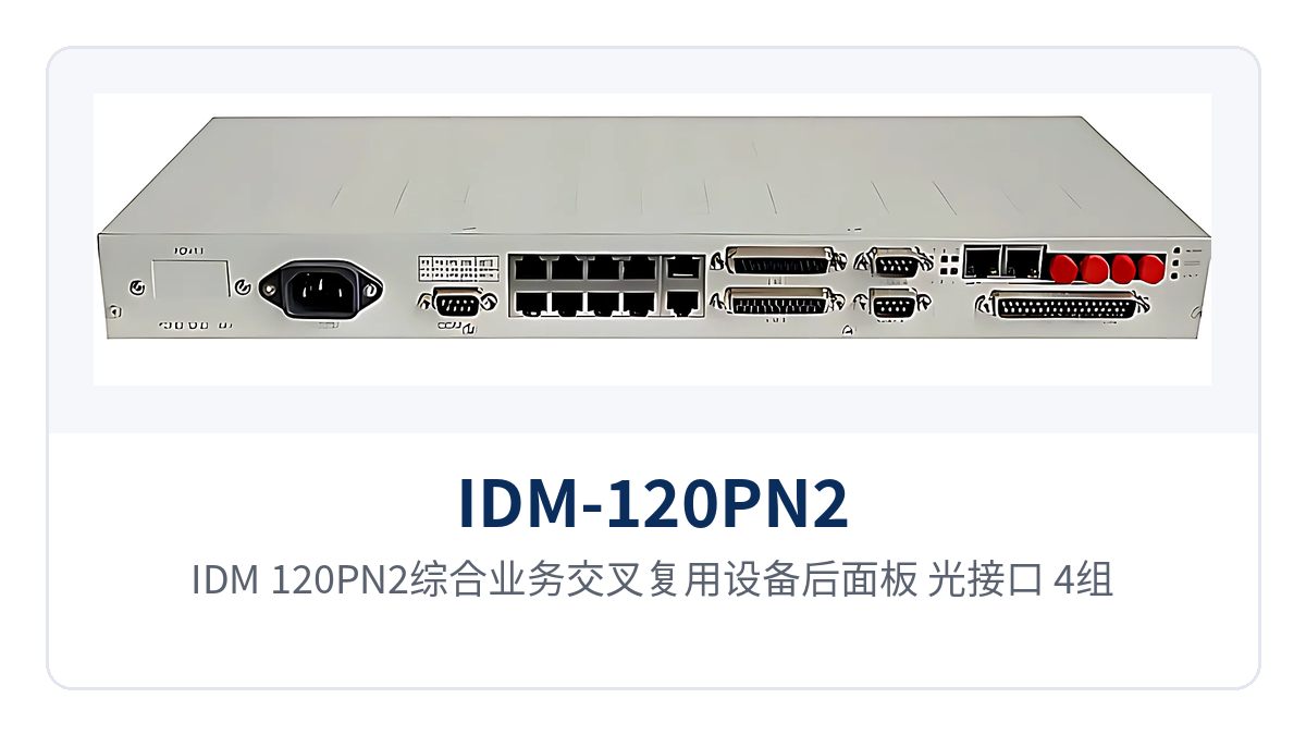
Figure 2: Rear panel of the IDM-120PN2 Integrated Service Cross-Connect Multiplexing Equipment, showing the layout of optical interfaces, 4 groups of E1 interfaces, and 2 groups of 100M Ethernet interfaces
What Services Do the 4 Groups of E1, Isolated Ethernet, and Serial Ports Connect Respectively
One side of the device has optical interfaces facing the line, and the other side has three types of service interfaces: E1, Ethernet, and serial ports. After each type of service enters the device, it is carried according to its own interface standard, and existing switching, dispatching, and monitoring devices do not need configuration changes. The interface types and quantities are configured after checking against the site service list, and the three types of services are converted and multiplexed within the same multi-service optical multiplexer, so the site side does not need to add a separate transmission device for each type of service.
How Are the 4 Groups of E1 Full Time-Slot Cross-Connections Used
- Full time-slot cross-connection: the time slots of the 4 groups of E1 signals can be cross-connected by configuration, so the voice channels and data of any input direction can be mapped to the specified output channel according to the service plan, and the service routing between sites is determined by the configuration.
- E1 single-end access: E1 services can be accessed at only one end of the device, and the device performs time slot allocation and sends them to the opposite end; on site, each item can be configured one by one according to the service list, and both ends do not need to be on site for construction at the same time.
- Transparent transmission: the E1 channel bit rate is 2048Kbps according to the ITU-T G.703 standard; after existing E1 devices are connected, services extend along the optical path to the opposite site, and the device does not parse the service content within the time slots.
The E1 frame structure determines where cross-connection scheduling lands. PCM30/32 is the frame structure standard of the E1 base group, and each frame is divided into 32 time slots, of which TS0 is used for frame alignment and alarms, TS16 is used for channel-associated signaling (CAS), and the remaining 30 time slots carry 64Kbps services; cross-connect configuration uses these time slots as units to allocate voice and data to specified positions in the target E1 channel, so when a site adjusts circuits, it changes the configuration without touching external cables.
How Are the 2 Groups of Physically Isolated Wire-Speed 100M Ethernet Divided into Domains
Physical isolation means that the 2 groups of physically isolated 100M Ethernet interfaces each have independent channels inside the device, rather than splitting one Ethernet port into two physical interfaces; the bandwidth and services of the two channels do not contend with each other, and each has wire-speed 100M forwarding capability. The isolation effect depends on the domain division scheme, so the interface assignment should be planned by service type before access.
- Dedicated bandwidth: the two Ethernet groups each use independent channels, so video backhaul and office access do not contend for bandwidth on the same forwarding path.
- Fault isolation: when abnormal traffic or a broadcast storm occurs on one channel, the services in use on the other channel are unaffected, and the fault scope is limited to a single service domain.
- Security domain division: monitoring, office, production, and other services are connected to different interfaces and carried separately by service nature, meeting the service isolation requirements of private networks.
How Do the Asynchronous RS232/RS485 and Channel-Associated Signaling Work Together
The device provides high-rate asynchronous RS232/RS485 interfaces for accessing low-speed data channels such as telecontrol and monitoring; serial port data is transmitted along the same optical chain as E1 and Ethernet services, so the site side does not need to lay separate cables for data services.
The channel-associated signaling modification mode can be flexibly adjusted according to the signaling mode of existing switching and PCM equipment, so telephone service access does not require changing the signaling configuration of the opposite device. The device supports multiple clock modes, and the line clock and site device clock can be selected according to on-site conditions to avoid clock wander during multi-point access. The above interface capabilities are described item by item in the product showcase of this optical multiplexer, and can be verified against the site service list during selection.
Summary Table of Functions and Performance Specifications
The following two tables are organized according to the product documentation: the function overview explains item by item what the device can do, and the key technical specifications give the indicators and applicable conditions item by item, with one function per row and one parameter per row, making it easy to check item by item during networking design and selection; electrical specifications not yet recorded in the knowledge base are listed in a separate row and need to be confirmed with the optical multiplexer manufacturer before ordering.
Function Overview
| Function | Description |
|---|---|
| Dual-optical-direction optical interfaces | Provides 2 groups of high-speed optical interfaces in two optical directions; the two directions can connect to the previous and next stations respectively to form an optical chain network |
| 4 groups of E1 cross-connections | Full time-slot cross-connection of 4 groups of E1 signals, with services allocated to target E1 channels according to plan |
| E1 single-end access | Supports E1 single-end access; after services enter the device at one end, the device allocates and sends them to the opposite end |
| 4 groups of E1 transparent transmission interfaces | Provides 4 groups of E1 transparent transmission interfaces; services of existing E1 devices are carried as-is without changing time slot content |
| 2 groups of physically isolated wire-speed 100M Ethernet | The two 100M Ethernet groups each use independent channels, with wire-speed forwarding and service domain separation |
| Asynchronous RS232/RS485 interfaces | Provides high-rate asynchronous RS232/RS485 interfaces for accessing low-speed data such as telecontrol and monitoring |
| Multiple clock modes | Line and site device clocks are selected according to on-site conditions, reducing clock wander during multi-point access |
| Channel-associated signaling modification | Flexible channel-associated signaling modification mode, adapting to the signaling modes of existing switching and PCM equipment |
| Unified network management and alarms | Unified network management and comprehensive alarm monitoring functions, with centralized monitoring of device status and alarms |
| Equipment room environment adaptability | Suitable for installation and use in communications equipment rooms under various environments |
Key Technical Specifications
| Item | Parameter/Specification | Description/Applicable Conditions |
|---|---|---|
| Device model | IDM-120PN2 | Integrated Service Cross-Connect Multiplexing Equipment, based on the IDM-120P platform |
| Optical interfaces | 2 groups of high-speed optical interfaces in two optical directions | The two directions can form a chain network; optical module rate, wavelength, and transmission distance are configured per order, subject to the manufacturer's technical documentation |
| E1 interfaces | 4 groups, transparent transmission | Bit rate 2048Kbps, compliant with the ITU-T G.703 standard, supporting E1 single-end access |
| E1 cross-connect capability | Full time-slot cross-connection of 4 groups of E1 signals | Configured in units of time slots within the E1 frame, with services mapped to target channels according to plan |
| Ethernet interfaces | 2 groups of wire-speed 100M, physically isolatable | The internal channels of the two groups of interfaces are independent, with access separated by service domain |
| Data interfaces | High-rate asynchronous RS232/RS485 | Used for access of low-speed data services such as telecontrol and monitoring |
| Clock modes | Multiple clock modes | Configured according to line and site device conditions |
| Signaling mode | Flexible channel-associated signaling modification mode | Adapts to the signaling modes of existing switching and PCM equipment |
| Network management functions | Unified network management, comprehensive alarm monitoring | Centralized monitoring of operating status and alarms, facilitating fault location |
| Installation environment | Suitable for communications equipment rooms under various environments | Rack installation; specific temperature and humidity conditions are subject to the manufacturer's technical documentation |
| Power supply, power consumption, dimensions | Not yet recorded in the knowledge base | Subject to the accompanying technical documentation and ordering configuration |
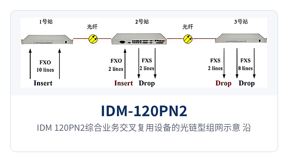
Figure 3: Schematic of the optical chain networking of the IDM-120PN2 Integrated Service Cross-Connect Multiplexing Equipment, with sites along the line connected in series via dual optical directions and aggregated at the central end
Typical Application Scenarios
The IDM-120PN2 Integrated Service Cross-Connect Multiplexing Equipment targets private network access scenarios that use optical fiber as the transmission medium and have sites scattered along a line, with target industries including electric power private networks, rail transit communication, and military and government private networks. As a key model in the product showcase of the professional optical multiplexer manufacturer Raytrans, the following three industry subsections respectively describe the site distribution patterns, the types of services accessed, and the changes brought by chain networking, which can be checked item by item against the corresponding subsections during on-site verification.
Substations and Power Supply Business Outlets of Electric Power Private Networks
Substations and remote power supply outlets usually have limited fiber core resources, and the station needs to upload three types of services: dispatch telephone, E1 telecontrol channels, and the monitoring network. This multi-service optical multiplexer connects voice channels, E1 channels, and the monitoring network separately within the station, and connects them in series into the optical chain along the line through the two optical directions, so the site side occupies only one segment of optical fiber.
The 2 groups of physically isolated Ethernet carry the monitoring network and the office network separately, so production control services and office services are independent of each other in the transmission segment, meeting the service domain division requirements of electric power private networks. The 4 groups of E1 cross-connections allow the telecontrol channels of each station to be mapped to specified channels according to the dispatching relationship, and new bays only require configuration changes. This telephone optical multiplexer from Raytrans has been maturely deployed in electric power government private network optical fiber communication solutions.
Stations Along the Line and Section Nodes of Rail Transit Communication
Rail transit stations along the line, section equipment rooms, and depots are distributed along a single optical cable path, and inter-station liaison telephone and monitoring data need to be aggregated uniformly at the central side. This optical multiplexer connects sites along the line via dual optical directions, and the telephone and data of each station are uploaded station by station through the optical chain, without the need to lay a separate optical cable back to the center for each station.
The rack position and power supply conditions of station communications equipment rooms are limited by the site, and one multi-service optical multiplexer handles E1, Ethernet, and serial port access simultaneously, so multiple single-function transmission devices no longer need to be stacked in the cabinet. Unified network management aggregates the device status of each station along the line to the network management center, and O&M personnel locate the specific station based on alarms.
Confidential Nodes and Field Sites of Military and Government Private Networks
Military and government private networks have high requirements for service isolation and operational continuity, and existing E1 leased line devices often have been running stably for many years, making full replacement costly. The 4 groups of E1 transparent transmission interfaces of this optical multiplexer connect existing services as-is and extend them to the opposite node, and the 2 groups of physically isolated Ethernet carry services separated by service nature, meeting the stringent service domain division requirements of government private network optical fiber communication solutions.
When field sites and mobile command posts are deployed in a chain along optical cables or temporary optical paths, the dual optical directions allow intermediate nodes to receive and transmit to both the previous and next stations simultaneously, and when a problem occurs in one direction in chain networking, a detour channel is still available. Unified network management and comprehensive alarm monitoring functions send node operating status to the superior network management center, so duty personnel do not need to inspect station by station.
Conclusion
As a dual-optical-direction cross-connect multiplexing optical multiplexer, the IDM-120PN2 Integrated Service Cross-Connect Multiplexing Equipment links sites along the line into an optical chain with 2 optical directions, adapts to the existing narrowband services of private networks with 4xE1 cross-connect and single-ended E1 access, and carries surveillance and office traffic in separate domains with 2 physically isolated wire-speed 100M Ethernet interfaces, saving both line resources and cabinet space.
The combination of chain networking and physical isolation allows the access nodes of electric power, rail transit, and military and government private networks to run telephone, telecontrol, and data services simultaneously over one optical chain. Raytrans recommends in its product showcase that, before deployment, the E1 channel allocation and Ethernet domain plan be confirmed against the site service list, and that optical module specifications and power supply conditions be subject to the manufacturer's technical documentation and ordering configuration.


