
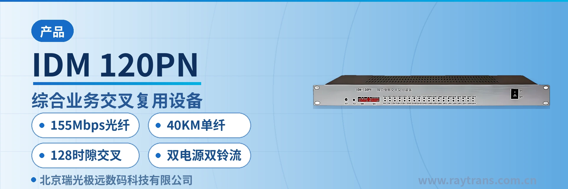
IDM-120PN Integrated Service Cross-Connect Multiplexing Equipment
4-channel E1 cross-connect, 4-channel E1 transparent transmission, 128-time-slot allocation, card-based expansion without replacing the entire unit
The IDM-120PN multi-service optical multiplexer uses dedicated large-scale integrated circuits and provides line-rate 100M Ethernet interfaces and 8 E1 interfaces over optical fiber, of which 4 E1 interfaces are used for cross-connect multiplexing and the other 4 E1 interfaces are used for transparent transmission. It is an optical multiplexing equipment that handles 2 to 4 optical signals. The IDM-120PN multi-service optical multiplexer uses a standard 19-inch 1U chassis with 8 universal slots and 2 expansion slots.
The 128-time-slot cross-connect multiplexing optical multiplexer is an access device that integrates the access, time slot scheduling, and optical fiber multiplexing of voice, data, and video surveillance services into a single unit, and it is also a typical product showcase from an optical multiplexer manufacturer for leased-line access scenarios. The IDM-120PN 128-time-slot cross-connect multiplexing optical multiplexer is developed by Beijing Ruiguang Jiyuan Digital Technology Co., Ltd. (Raytrans) for voice, data, and video surveillance leased-line access in power, public security, finance, schools, and other systems.
The device uses dedicated large-scale integrated circuits and provides line-rate 100M Ethernet interfaces and 8 E1 interfaces over optical fiber, of which 4 E1 channels are used for cross-connect multiplexing and 4 E1 channels for transparent transmission, handling 2 to 4 optical signals. The optical fiber rate is 155Mbps, the single-fiber transmission distance is no less than 40KM, and the optical interface is available in SC/FC/ST, allowing direct connection to the existing optical patch panel in the equipment room. As a multi-service optical multiplexer, the device can simultaneously carry voice, data, and video surveillance services; in video access scenarios, it can also be used as a video optical multiplexer and, together with telephone optical multiplexers, forms an integrated access solution suitable for applications such as government private network optical fiber communication solutions and smart mining communication solutions.
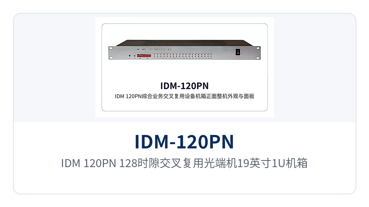
Figure 1: Front appearance and panel alarm indicator LEDs of the IDM-120PN 128-time-slot cross-connect multiplexing optical multiplexer 19-inch 1U chassis
Key Specifications at a Glance: 155Mbps optical fiber · 40KM single-fiber transmission · 128 time slots cross-connect · 4 E1 cross-connect + 4 E1 transparent · 1 to 4 100M Ethernet · dual power supply and dual ringing current backup
What are the components of this 128-time-slot cross-connect multiplexing optical multiplexer?
The IDM-120PN uses a standard 19-inch 1U chassis with 8 universal slots and 2 expansion slots, and interface cards are configured according to the site service list. The unit can provide 16 64K plus 8 n×64K subscriber interfaces, and the 24 subscriber interface services can be transmitted over 4 E1 directions; capacity expansion is achieved by adding cards without replacing the entire unit. As an optical multiplexer product showcase for multiple scenarios, its slot-based structure allows the same platform to flexibly adapt to the service requirements of different sites.
The subscriber interfaces use an independent module design, and more than 30 interface types—including 64K codirectional, V.24/V.28, V.35, 10Base-T, FXO/FXS, magneto, hotline, EM 2/4-wire audio, and high-fidelity audio—can be changed according to site requirements. The independent subscriber modules allow the same chassis to adapt to the service structure of different sites, reducing the variety of spare parts and the amount of on-site modification. This modular design is also a common practice among professional optical multiplexer manufacturers across telephone optical multiplexer and multi-service optical multiplexer product lines, and Raytrans continues this approach in this series.
The device provides optical fiber line receive/transmit in four transmission directions and can be combined with the IDM-240, IDM-120, IDM-30, and IDM-mini series to form chain networks, star networks, and tree networks. The number of optical directions is determined by site capacity requirements and distribution, the service allocation on a single 155Mbps optical path is adjusted accordingly, and networking costs are controlled according to the actual number of sites, serving networking scenarios such as government private network optical fiber communication solutions and smart mining communication solutions.
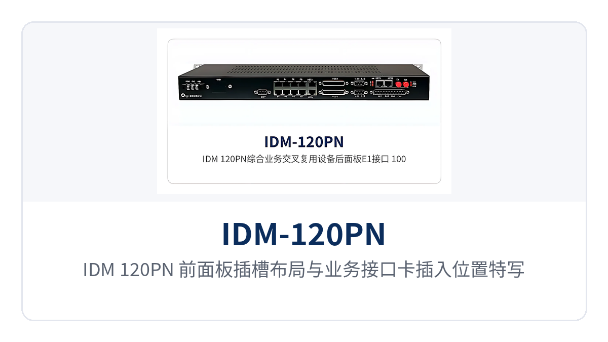
Figure 2: Close-up of the front panel slot layout and service interface card insertion positions of the IDM-120PN
Which services can a single device access simultaneously?
The functions of the IDM-120PN cover four categories: service access, time slot scheduling, optical fiber multiplexing, and centralized monitoring, with voice, data, and video surveillance access, multiplexing, and allocation completed within the same chassis. Each function and its purpose are listed row by row in the table below; interface cards are configured according to the site service list, and one multi-service optical multiplexer simultaneously performs the roles of PCM multiplexing and E1 time-slot cross-connect.
| Function | Description |
|---|---|
| Optical fiber multiplexing | 4 E1 transparent transmission and 4 E1 cross-connection, while providing 1 to 4 Ethernet channels and handling 2 to 4 optical signals |
| Line-rate 100M Ethernet | Interfaces operate in full-duplex/half-duplex, 10M/100M adaptive mode, with data frame filtering and MAC address auto-learning, supporting VLAN and flow control |
| Two-level time slot cross-connect | Built-in 128-time-slot cross-connect matrix enables user-to-user, user-to-line, and line-to-line cross-connection of data and signaling |
| Multi-timeslot card channels | Built-in 4 multi-timeslot card channels can accommodate V.35 cards and 10BASE-T cards with n×64K bandwidth, and can also provide high-speed asynchronous RS232/RS485 interfaces |
| Built-in Ethernet switching board | One Ethernet interface can be expanded to 4 groups of 100M Ethernet interfaces, so no additional switch is needed on the site side |
| Flexible subscriber interface configuration | Independent subscriber module design, with more than 30 interface types—including 64K codirectional, V.24/V.28, V.35, FXO/FXS, magneto, hotline, EM 2/4-wire audio, baseband trunk, and Signaling System No. 1—freely configurable |
| Multiple clock modes | Can be set as master clock, external clock, line clock, or user clock; interfaces can be set to exchange side or user side, compatible with both central office and remote end |
| Network management and alarms | RS232 and RS485 network management interfaces; RS485 cascaded network management can cascade multiple devices simultaneously, with rack alarm output; an audible alarm is issued when E1 status changes, and panel indicator LEDs show the alarm state |
| Dual power supply and dual ringing current backup | Dual power supply and dual ringing current modules are used; the power supply operates in half-power mode to extend service life, and the unit continues to operate normally if a single module fails |
| Flexible networking | Provides optical fiber line receive/transmit in 4 transmission directions and can be combined with the IDM-240, IDM-120, IDM-30, and IDM-mini series to form chain networks, star networks, and tree networks |
How do the 4 E1 cross-connect and 4 E1 transparent channels divide their work?
The 4 E1 cross-connect multiplexing channels are responsible for scheduling local site services to the target E1 time slots, while the 4 E1 transparent channels are responsible for passing existing E1 services through to the opposite end unchanged; the two types of channels work in parallel within the same device. Narrowband services such as telephone and V.24 data use the cross-connected channels, while existing E1 services such as digital trunks and PCM multiplexers use the transparent channels. For surveillance video services carried by video optical multiplexers, transmission can also be coordinated through Ethernet channels and E1 channels.
Knowledge block: 128-time-slot cross-connect matrix. The E1 interface uses the PCM30/32 frame structure; each E1 channel contains 32 time slots, with TS0 used for frame alignment and alarms, TS16 carrying channel-associated signaling (CAS), and the remaining 30 time slots carrying 64K services. The 4 E1 channels total 128 time slots, corresponding one-to-one with the built-in 128-time-slot cross-connect matrix. The E1 interface electrical characteristics comply with ITU-T G.703, and the bit rate is 2.048Mbps.
Cross-connection relationships can be established at three levels—user-to-user, user-to-line, and line-to-line—with data and signaling switched together. When services are added or redirected, only the cross-connect configuration is adjusted, while external optical cables and telephone wiring remain unchanged, minimizing on-site modification and avoiding impact on other circuits in use.
The 128-time-slot cross-connect is implemented inside the device, so the 4 E1 cross-connect channels eliminate the need to separately purchase an E1 time-slot cross-connect equipment; a single investment at the access node covers both optical transmission and time slot scheduling. Cabinet space is reduced from two devices to one 1U device, and the number of supporting power supplies and cables decreases accordingly—a direct benefit of 128-time-slot scheduling without a separate cross-connect device.
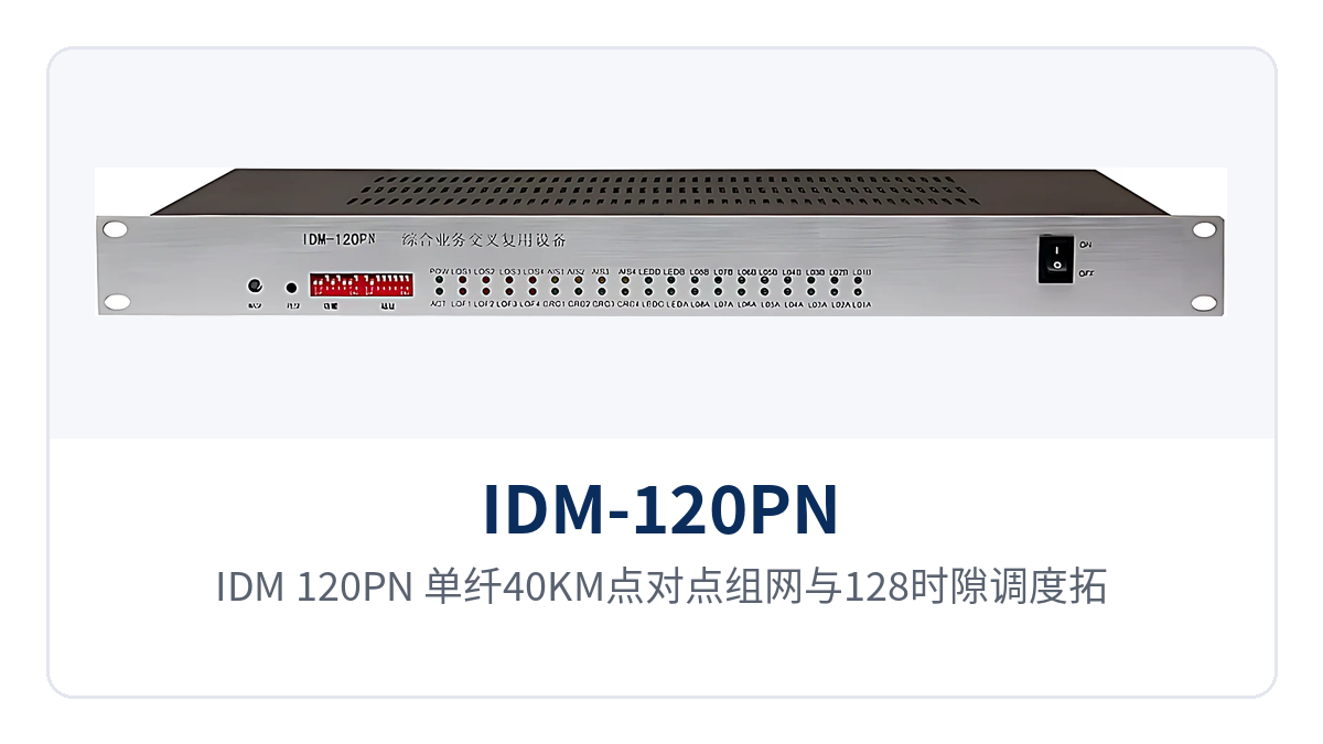
Figure 3: Schematic diagram of IDM-120PN single-fiber 40KM point-to-point networking and 128-time-slot scheduling topology
Technical Specifications
The optical interface, E1 interface, and subscriber interface parameters of the IDM-120PN are listed item by item in the table below, with transmission distance given for single-fiber transmission mode. The optical interface form is selected according to the on-site optical cables and optical patch panel; interface card configuration and optical module models are confirmed per project, and items not listed in the table are subject to the manufacturer's technical documentation.
| Item | Parameter/Specification | Description/Applicable Conditions |
|---|---|---|
| Optical fiber rate | 155Mbps | Optical line transmission rate, corresponding to the 155Mbps optical fiber in the at-a-glance row |
| Transmission distance | No less than 40KM | Single-fiber transmission mode; actual distance is determined by the optical module and optical cable attenuation |
| Optical interface form | SC/FC/ST selectable | Direct connection to the existing optical patch panel in the equipment room |
| Optical direction | 2 to 4 | Optical fiber line receive/transmit in four transmission directions can be provided |
| E1 interface | 8 channels (4 cross-connect + 4 transparent) | Bit rate 2.048Mbps, PCM30/32 frame structure, compliant with ITU-T G.703 |
| Ethernet interface | 1 to 4 100M | Line-rate forwarding, full-duplex/half-duplex, 10M/100M adaptive |
| Cross-connect capacity | 128 time slots | 4 E1 × 32 time slots, supporting user-to-user, user-to-line, and line-to-line cross-connection |
| Subscriber interface capacity | 16 64K + 8 n×64K | 24 subscriber interface services can be transmitted over 4 E1 directions |
| Chassis and slots | 19-inch 1U, 8 universal slots + 2 expansion slots | Easy to install in a standard rack; cards configured per service list |
| Clock mode | Master clock/external clock/line clock/user clock | Can be set to exchange interface or user interface, compatible with both central office and remote end |
| Network management interface | RS232, RS485 | RS485 cascaded network management can cascade multiple devices simultaneously, with rack alarm output |
| Power supply and ringing current | Dual power supply, dual ringing current backup | Power supply operates in half-power mode; the unit continues to operate normally if a single module fails |
Dual power supply and dual ringing current backup is the reliability design of this device for unattended sites: two power supply modules and two ringing current modules are online simultaneously, each carrying half the load. The power supply operates in half-power mode for long periods, resulting in lower temperature rise and losses; if a single module fails, the other module continues to supply power and ringing current, and the unit's services remain normal, allowing maintenance to be scheduled in a planned window. As an optical multiplexer manufacturer, Raytrans provides this backup mechanism on this model as a standard configuration for continuous-operation scenarios such as government private network optical fiber communication solutions and smart mining communication solutions.
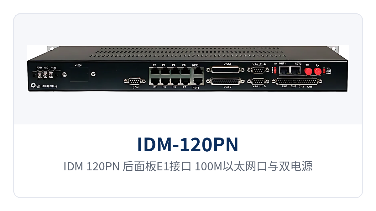
Figure 4: Close-up of the rear panel E1 interfaces, 100M Ethernet ports, and dual power supply and dual ringing current modules of the IDM-120PN
What are the typical access scenarios?
The IDM-120PN is intended for leased-line access applications such as electric power private networks, public security video surveillance private networks, finance, and schools: the site side needs to upload voice, low-speed data, video surveillance, and existing E1 channels simultaneously, while optical cable resources are limited. The 155Mbps optical fiber and 40KM single-fiber transmission make one-site-one-fiber networking feasible over long-distance lines, eliminating the need to cascade trunk equipment between the site and the center. As a multi-service optical multiplexer, the device completes integrated access of voice, data, and video on the same platform, also providing a reusable access node for subsequent government private network optical fiber communication solutions and smart mining communication solutions.
Electric power private network: simultaneous transmission of substation voice, telecontrol, and surveillance
Substations and switching stations need to upload dispatch telephone, telecontrol data, and video surveillance to the centralized control station, and the number of available optical cable cores within the station is usually limited. The IDM-120PN connects voice channels and low-speed data to the cross-connected channels and allocates them to designated E1 channels by 64K time slot; video surveillance is accessed through 100M Ethernet ports and shares the same pair of optical fibers with voice, and 40KM single-fiber direct connection can eliminate intermediate trunk cabinets.
The access mode for dispatch telephone is configured according to the type of exchange in the station; FXO, FXS, magneto, hotline, and other interfaces are all available, so existing telephones do not need to be replaced. When E1 status changes, the device issues an audible alarm and outputs a rack alarm, and the network management side can check link status at any time, reducing the inspection frequency of unattended sites.
Figure 5: IDM-120PN installed in a substation communications cabinet, with optical cables and E1 cables connected on site
Public Security Video Surveillance Private Network: Image and Voice Leased-Line Same-Fiber Backhaul
A public security video surveillance site usually has only one pair of optical fibers available for uplink, and the front-end camera images, checkpoint data and guard booth telephone calls need to be backhauled at the same time. When used as a video optical multiplexer, the IDM-120PN provides 1 to 4 100M Ethernet channels to carry images and data, and E1 channels to carry voice and existing leased-line services, with the two service types each occupying their own channels over the same fiber core.
The Ethernet channels support VLAN and flow control, so the surveillance network and the office network can be separated by VLAN partitioning, and image traffic will not squeeze out service channels. The 40KM single-fiber transmission distance suits direct-connection coverage of checkpoints in the urban periphery and suburbs, reducing one level of trunk equipment and supporting cabinets between checkpoints and branch bureaus.
Financial and School Leased-Line Access: Branch Call Handling and Data over the Same Link
Bank branches, school campuses and their superior institutions need to run both internal call handling and office data and video surveillance. The IDM-120PN uses a pair of optical fibers to send call handling, data and surveillance services together to the superior equipment room; the branch side occupies only one 1U rack position, and call handling and data access are completed on the same device.
Subscriber interfaces are configured according to the actual services of the branch: branches with fewer voice channels get fewer cards, and branches with more voice channels get more cards; for capacity expansion, simply add interface cards. RS485 cascaded network management can connect multiple devices in one equipment room to the same network management bus for centralized viewing of operating status and fault statistics.
How to Select and Deploy a 128-Time-Slot Cross-Connect Multiplexing Optical Multiplexer?
Selection starts from the site service list: check the number of service channels, E1 directions, optical interface distance, clock mode and network management power supply in five items, and the configuration can then be fixed. The following five items describe what to check in each and common practice, so that the site and commercial sides can confirm in sync and avoid adding plug-in cards after ordering.
- Count service types and number of channels: the respective quantities of telephone, magneto, audio, V.24 data, V.35 data and Ethernet, on which the types and number of interface cards are determined; the subscriber interface services of a standalone unit do not exceed 24 channels.
- Allocate E1 channels: services requiring cross-direction dispatching go to the 4-channel E1 cross-connect multiplexing side, and services requiring direct interfacing with existing equipment or leased circuits go to the 4-channel E1 transparent side; the quantities on the two sides are calculated separately.
- Select optical interfaces and distance: choose SC/FC/ST interfaces according to the equipment room and the optical distribution frame, check the optical modules against a single-fiber specification of no less than 40KM, and in single-fiber mode confirm that the opposite-end equipment also supports single-fiber receive/transmit.
- Specify clock and interface side: set master clock, external clock, line clock or user clock according to the existing transmission system, and set the interface to the switch side or user side according to whether the opposite end is a switch or a terminal.
- Confirm network management and power supply: for unified management of multiple sites, use RS485 cascaded network management to connect devices in series; for unattended sites, equip dual power supply and dual ringing current modules and connect two independent power feeds.
During wiring, connect the optical path first and then the services; configure optical ports in pairs in single-fiber mode, install E1 interfaces with 75 Ω coaxial or 120 Ω balanced cables, and match service interface cards channel by channel according to the front panel labels. After power-on, first check the panel indicator LEDs, then read E1 status and alarm information from the network management, and connect the formal circuits only after confirming that services in all directions are normal. For multi-site scenarios in government private network optical fiber communication solutions and smart mining communication solutions, the same procedure can be used to check site by site, ensuring consistent configuration at each node and unified network management.
Conclusion
The IDM-120PN 128-time-slot cross-connect multiplexing optical multiplexer integrates 8 E1 channels, wire-speed 100M Ethernet and a 128-time-slot cross-connect matrix in a 19-inch 1U chassis, and supports long-distance access for private networks in electric power, public security, banking and schools with 155Mbps optical fiber, 40KM single-fiber transmission and dual power supply and dual ringing current backup. As an optical multiplexer manufacturer, Raytrans (Beijing Ruiguang Jiyuan Digital Technology Co., Ltd.) continues to provide selection and deployment support for this multi-service optical multiplexer in its product showcase, making it easy for users to obtain integrated access capability beyond telephone optical multiplexers and video optical multiplexers.
An access node uses one optical multiplexer to complete service access, time-slot scheduling and network management monitoring; 4-channel E1 cross-connect and 4-channel E1 transparent transmission run in parallel, time slots are allocated according to actual occupancy, and cabinet space and supporting power supply are reduced accordingly. Service expansion is completed by inserting cards and changing the configuration, while external optical cables and telephone wiring remain untouched.


