
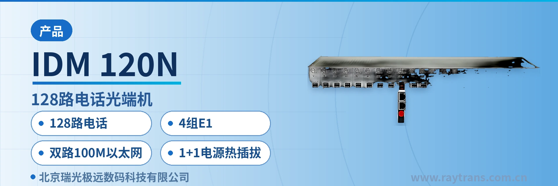
IDM-120N 128-Channel Telephone Optical Multiplexer
One unit replacing three units; voice channels, E1, and Ethernet over a single fiber; dual-card hot-swappable replacement without ringing interruption
The IDM-120N 128-channel multi-service optical multiplexer is a PCM integrated service optical fiber transmission equipment designed by our company using dedicated large-scale integrated circuits. Its total optical fiber transmission bandwidth is 155M, providing 2 shared line-rate 100M Ethernet interfaces, 4 groups of E1 transparent transmission interfaces, and 128 telephone subscriber channels. The IDM-120N 128-channel multi-service optical multiplexer also features dual backup and hot-swappable functions for the power card and ringing current card, greatly ensuring the reliability of service transmission.
IDM-120N is a 128-channel multi-service telephone optical multiplexer developed by Beijing Ruiguang Jiyuan Digital Technology Co., Ltd. It adopts a dedicated large-scale integrated circuit design and is a PCM integrated service optical fiber transmission equipment, used to simultaneously carry 128 telephone subscriber channels, 4 groups of E1 transparent transmission interfaces and 2 shared line-rate 100M Ethernet channels over a single 155M optical link. As a professional optical multiplexer manufacturer, Raytrans continues in this product the pursuit of high integration and stability reflected in its product showcase.
The unit is a 19-inch 3U card-based chassis, providing 19 card slots and 16 subscriber interface slots. Voice channel capacity is configured by combining FXO/FXS service cards, and expansion only requires adding cards as services grow. Power supply, temperature and humidity conditions are set for an indoor equipment room environment, targeting site access for electric power private networks, rail transit communication and military and government private networks. The optical multiplexer flexibly adapts to the voice access requirements in government private network optical fiber communication solutions and military emergency communications vehicle solutions, building a multi-level transmission system together with PDH optical multiplexers and other equipment.
Key Specifications at a Glance: 128 telephone subscriber channels · 155M optical fiber transmission bandwidth · 4 groups of E1 transparent transmission (ITU-T G.703, PCM30/31) · dual 100M Ethernet · 1+1 hot-swappable dual backup power supplies · 19-inch 3U chassis with 16 subscriber slots
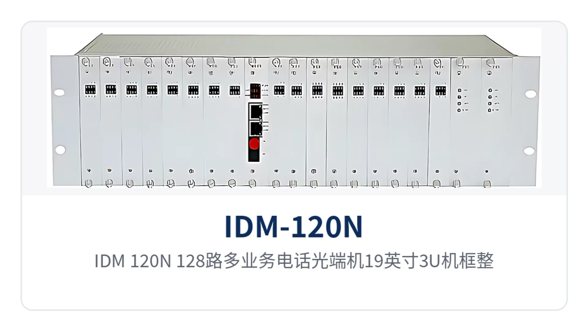
Figure 1: IDM-120N 128-channel multi-service telephone optical multiplexer, 19-inch 3U chassis front view, close-up of card slots and alarm indicator LEDs
What kind of equipment is the 128-channel multi-service telephone optical multiplexer?
The 128-channel multi-service telephone optical multiplexer solves the problem of many service types and limited rack space at a site: analog telephones, E1 leased lines and IP data previously each required a separate transmission device, while this optical multiplexer consolidates all three service types into one chassis and delivers them over a single optical link to the far end for faithful restoration. The devices are used in pairs: one end connects to telephones and leased-line equipment, and the other end restores telephone, E1 and RJ-45 interfaces.
How many telephone, E1 and Ethernet channels can one fiber carry
How many telephone channels one fiber can carry is determined by the optical link bandwidth and the time slot occupation of each voice channel: a single 155M optical link is divided into three independent service channels that do not contend with each other. The telephone channel compresses each voice signal into 64Kbps using ITU-T G.711 A-law, with 128 channels totaling about 8.2M; the loop current is 25mA per channel, and the voice channels are implemented by combining 8-channel-per-card FXO/FXS service cards.
The E1 channel provides 4 groups of 2048Kbps transparent channels in PCM30/31 format with channel-associated signaling, and can directly interface with existing PCM and SDH equipment. The Ethernet channel provides 2 RJ-45 interfaces, 10/100Base-T, compliant with IEEE802.3, with shared line-rate 100M. The three service types together remain within the capacity of the 155M optical link, and the site side occupies only one optical fiber link.
What functions and interfaces does the IDM-120N provide
As a multi-service optical multiplexer, the IDM-120N covers five categories of capability: voice channel access, E1 transparent transmission, Ethernet multiplexing, card-based expansion and redundancy protection. Their respective uses and applicable conditions are listed in the table below. For selection, check against the on-site service list: first count the voice channels and E1 directions, then check the number of Ethernet ports and the power supply mode.
| Function | Description |
|---|---|
| 128 telephone subscriber channels | A single unit provides 128 voice channels; FXO connects to the exchange side and FXS connects to the user telephone side; both interface types support polarity reversal and caller ID |
| 4 groups of E1 transparent transmission interfaces | 4 groups of E1 channels, bit rate 2048Kbps, HDB3 line code, compliant with ITU-T G.703, 75Ω/120Ω impedance selectable, channel-associated signaling transparently transmitted |
| Dual 100M Ethernet | 2 RJ-45 interfaces, 10/100Base-T, compliant with IEEE802.3, full/half duplex adaptive, shared line-rate 100M on the optical link side |
| 16 subscriber interface slots | 3U chassis with card-based structure; 8FXO-120 and 8FXS-120 service cards are inserted according to voice channel direction; voice channel capacity is configured by combining cards |
| 1+1 hot-swappable power supplies | Power card PRU-120 and power and ringing current card RPRU-120 are each configured as 1+1; a single card failure can be replaced directly during operation |
| Multi-function card slot expansion | Reserved multi-function card slot for flexible expansion as services grow, supporting any network topology |
| Function control switch and alarm indication | The panel provides a function control switch and alarm indication, facilitating on-site commissioning and fault location |
| Online network management | Supports online real-time configuration, query and fault statistics management, and enables centralized maintenance together with alarm indication |
How one 3U device replaces stacked devices
Consolidating three service types into one 3U device and occupying fewer cabinets and less cabling is the core value of this multi-service optical multiplexer. The on-site benefits corresponding to the three differentiation points are listed row by row in the table below. During selection discussions, check against the project pain points; if a row does not match, it means that capability is not essential for the project.
| Differentiation Point | Value to Private Network Sites |
|---|---|
| 128 telephone channels · 4 groups of E1 · dual 100M Ethernet | One unit replacing multiple units: high-capacity line provisioning and E1 leased-line and IP data access in the same chassis; the site no longer needs separate voice equipment, PDH optical multiplexers and media converters for each service type |
| 1+1 hot-swappable power supplies | The power card and ringing current card are each configured as 1+1; when a single card fails, it can be hot-swapped during operation, so services are uninterrupted in the power supply and ringing links |
| 155M optical bandwidth, receiver sensitivity better than -36dBm | The 155M bandwidth delivers voice channels, E1 and Ethernet in one pass; receiver sensitivity better than -36dBm allows stable operation on weak optical links with relatively high optical cable attenuation |
Chassis card composition and how to expand 128 voice channels
The IDM-120N consists of a chassis backplane, main control cards, power cards (power and ringing current cards) and FXO/FXS service cards. The models and functions of each card are listed in the table below. In a single-unit configuration, only one of the E1 interface main control card and the optical interface main control card can be selected; the site decides the main control card type based on whether E1 access is required.
| No. | Name | Model | Description | Quantity |
|---|---|---|---|---|
| 1 | Equipment chassis backplane | IDM-120 | 19-inch 3U chassis, providing 19 card slots | 1 |
| 2 | E1 interface main control card | CMU-E1-120 | Provides E1 interface access | 1 |
| 3 | Optical interface main control card | CMU-120 | Provides 1 group of optical interface access, 2 groups of line-rate 100M Ethernet interfaces, 4 groups of E1 interfaces | 1 |
| 4 | Power card | PRU-120 | Provides 1+1 power supply and overall power supply, used on the FXO side, -48V input | 2 |
| 5 | Power and ringing current card | RPRU-120 | Provides 1+1 power supply, overall power supply and ringing voltage, used on the FXS side, -48V input | 2 |
| 6 | FXO service card | 8FXO-120 | 8 FXO interfaces, exchange side | As required |
| 7 | FXS service card | 8FXS-120 | 8 FXS interfaces, user side | As required |
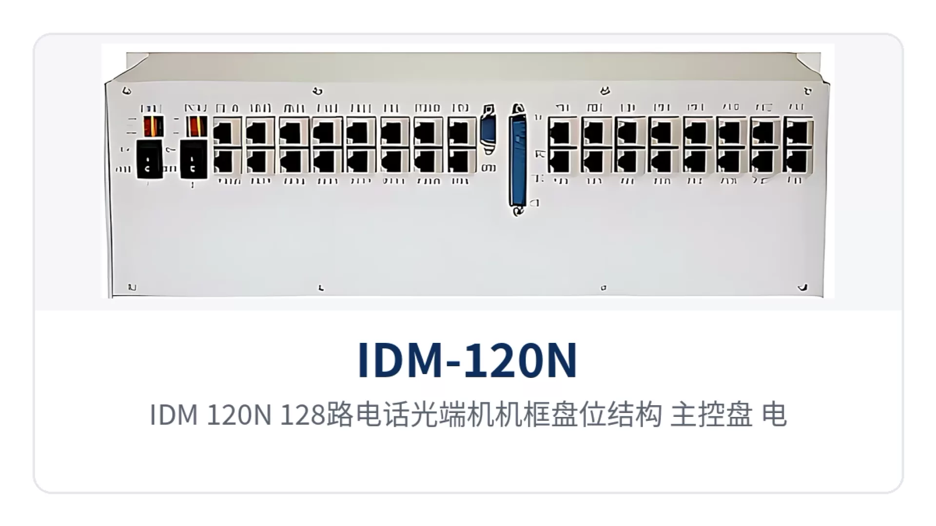
Figure 2: IDM-120N 128-channel telephone optical multiplexer chassis card slot structure, showing the insertion of main control cards, power and ringing current cards, and 8-channel FXO and FXS service cards
How to expand when 128 voice channels are insufficient
The capacity expansion approach for the 128-channel multi-service telephone optical multiplexer is to add service cards in the card-based chassis. The chassis provides 19 card slots and 16 subscriber interface slots; voice channels are implemented by combining 8-channel-per-card FXO-120 and 8FXS-120 cards by direction. As services grow, simply add cards of the corresponding direction, and the reserved multi-function card slot can also carry subsequent expansion without replacing the entire unit. As a professional optical multiplexer manufacturer, Raytrans provides overall support from product showcase and selection consulting to government private network optical fiber communication solutions and military emergency communications vehicle solutions, making it convenient for users to plan the deployment of PDH optical multiplexers and multi-service optical multiplexers in a unified way in expansion and new-build projects.
Technical Specifications and Interface Specifications
Parameters are listed by group: optical interface, E1 interface, Ethernet, telephone interface, and power supply and environment. On the optical side, calculate the link margin based on transmit optical power and receiver sensitivity; on the electrical side, check compatibility with the peer device based on impedance and frame structure. For missing items, refer to the technical documentation supplied with the unit. The following specifications apply to the IDM-120N multi-service optical multiplexer in the Raytrans series optical multiplexer product showcase.
Optical Interface Parameters
| Item | Parameter/Specification | Description/Applicable Conditions |
|---|---|---|
| Interface type | FC (SC and others can be customized) | Selected according to the peer optical adapter and patch cord type |
| Fiber mode | Single-mode (multimode optional) | Selected according to on-site optical cable conditions, used in pairs at both ends |
| Optical fiber rate | 155bps±50ppm | Nominal value in product documentation, corresponding to the overall 155M optical fiber transmission bandwidth |
| Wavelength | 1310nm | Single-mode fiber transmission window |
| Transmit optical power | -2~-11dBm | Transmit optical power range, used for link attenuation calculation |
| Receiver sensitivity | Better than -36dBm | Bit errors are likely when received optical power is below this value |
E1 Interface Parameters
| Item | Parameter/Specification | Description/Applicable Conditions |
|---|---|---|
| Bit rate | 2048Kbps | Standard E1 bit rate |
| Line code | HDB3 | Compliant with ITU-T G.703 line code requirements |
| Standard protocol | Supports ITU-T G.703 | E1 electrical interface standard |
| Impedance | 75Ω/120Ω | Coaxial or balanced interface selectable |
| Frame structure | PCM30/31 | Voice channels organized in PCM30/31 format |
| Signaling | Channel-associated signaling | Common signaling method for interfacing with existing exchange and PCM equipment |
Ethernet and Telephone Interface Parameters
| Item | Parameter/Specification | Description/Applicable Conditions |
|---|---|---|
| Ethernet interface type | RJ-45 | 2 Ethernet electrical interfaces |
| Ethernet transmission rate | 10/100Base-T, 10M/100M | Rate adaptive, shared line-rate 100M on the optical link side |
| Ethernet standard protocol | Supports IEEE802.3 | Can be directly connected to Ethernet devices such as switches |
| Ethernet operating mode | Full/half duplex/adaptive | Auto-negotiation with the peer |
| Audio range | 300Hz~3400Hz | Telephone voice band |
| Telephone interface impedance | Three-element complex impedance 200Ω+560Ω//0.1μF | Return loss characteristics of the telephone interface |
| Compression | ITU G.711 A-law | Voice codec |
| Loop current | 25mA per channel | Feeding capability for the telephone set |
Power Supply, Environment and Chassis
| Item | Parameter/Specification | Description/Applicable Conditions |
|---|---|---|
| Power supply mode | DC-48V or AC 220V | Selected according to equipment room or on-site power supply conditions |
| Overall power consumption | ≤250W | Calculated according to site power capacity and cabinet heat dissipation conditions |
| Operating temperature | 0℃~+40℃ | Suitable for indoor equipment room environment |
| Humidity | 95% non-condensing | Relative humidity requirement |
| Product dimensions | 480×200×132mm (Length×Depth×Height) | Installation dimensions of the 19-inch 3U chassis |
Typical Application Scenarios: Electric Power, Rail Transit and Military and Government Private Networks
The following three types of sites are typical deployments for this device, all using point-to-point networking: one unit at the service site, one unit in the central equipment room or centralized control station, and a single optical path in between carrying all services. The common constraints across these three site types are tight rack positions, long pole routes, and high on-site visit costs, and the equipment form factor and interface combinations are organized around these constraints. As a professional optical multiplexer manufacturer, Raytrans has accumulated extensive deployment experience in scenarios such as electric power private network optical fiber communication solutions and military emergency communications vehicle solutions.
Electric Power Private Network: Substation Telephone and E1 Telecontrol Services Uplinked over the Same Fiber
Electric power private network sites usually need to enable dispatch telephone and office telephone services at the same time, and to interconnect with E1 leased lines carrying telecontrol and metering data. At the substation side, this 128-channel multi-service optical multiplexer delivers voice channels through FXO/FXS interfaces, transports 4 groups of E1 to the centralized control station via ITU-T G.703 transparent transmission, and backhauls in-station IP services over 2-channel Fast Ethernet, completing three types of access over a single 155M optical path, so there is no need to stack voice equipment and PDH optical multiplexers in the cabinet.
Sites are mostly unattended, with power supplied at DC-48V from the in-station communications power supply; the power card and the power and ringing current card are each configured with 1+1 redundancy, and a faulty card can be replaced by hot-swappable replacement during operation, so the power supply and ringing current links are not interrupted and on-duty personnel do not need to make a special site visit for this. This solution has been deployed and verified in multiple electric power private network optical fiber communication solution projects.
Rail Transit Communication: Channel Extension Across Stations, Section Equipment Rooms and Depots
Dedicated telephone, public address (PA) and monitoring data need to be transmitted among stations along the line, section equipment rooms and depots in rail transit; sites are distributed, spacing is long, and cabinet slots and fiber cores are both in short supply. This telephone optical multiplexer uses a 19-inch 3U card-based chassis that can be installed in standard cabinets along the line, with voice channels, E1 and Ethernet transmitted over the same fiber, so the rack positions and wiring required at the site side are relatively few.
Power supply formats vary from site to site along the line, and the two power supply modes of AC 220V and DC-48V can be configured per station, reducing the variety of spare parts accordingly; the device operates at an operating temperature of 0℃~+40℃ and a humidity of 95% non-condensing, making it suitable for communications equipment rooms and equipment cabinets with ventilation, and convenient for installation in the same cabinet as other transmission devices.
Military and Government Private Networks: Service Access for Remote Sites and Temporary Command Posts
Sites of military and government private networks are often located in remote areas with limited duty conditions, placing concentrated requirements on link continuity and on-site maintainability. This multi-service optical multiplexer complements power-side redundancy with 1+1 redundancy of the power card and the ringing current card plus hot-swappable capability, and brings operating status to the equipment room through online network management and front panel alarms, reducing the number of site visits. Raytrans's military emergency communications vehicle solution also adopts this equipment form factor to meet rapid commissioning requirements under mobile conditions.
Temporary command posts or mobile sites require rapid commissioning: place one unit at each end and connect the optical fiber to restore voice channel, E1 and Ethernet interfaces, without changing the configuration of the opposite-end equipment; the point-to-point structure makes link relationships clear, facilitating adjustment of node positions according to tasks and replacement of optical interface types according to on-site conditions.
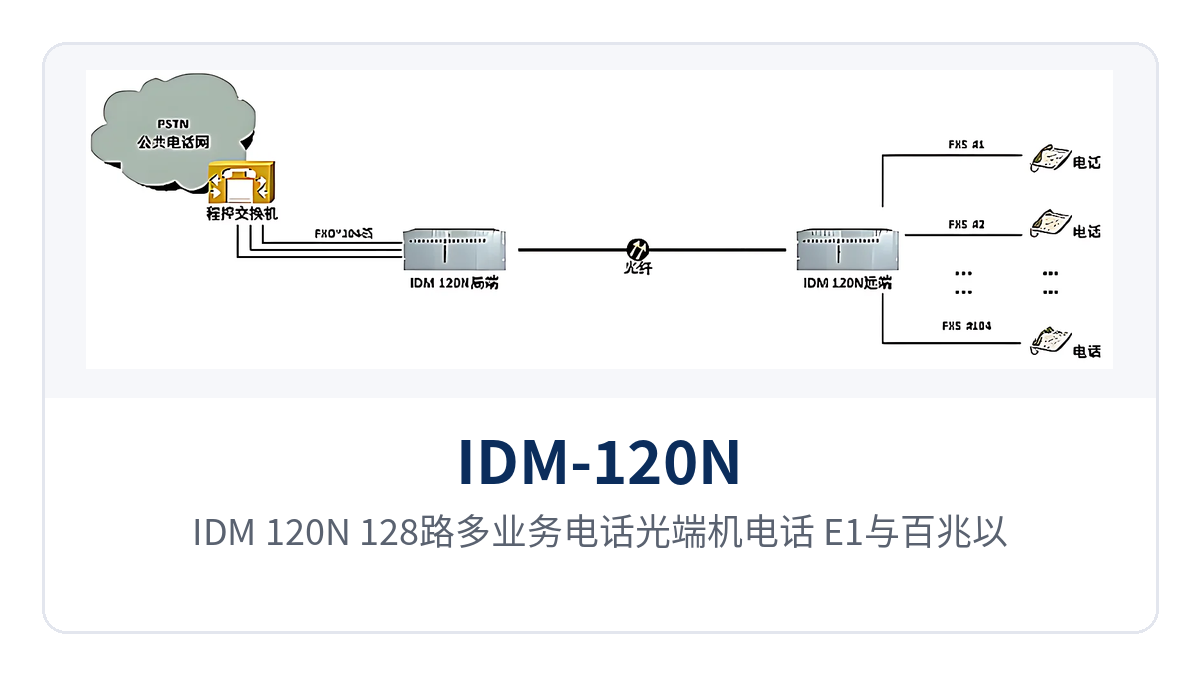
Figure 3: IDM-120N 128-channel multi-service telephone optical multiplexer point-to-point networking topology schematic for telephone, E1 and Fast Ethernet
Conclusion
As a 128-channel multi-service telephone optical multiplexer, IDM-120N carries 128 voice channels, 4 groups of E1 and dual-channel 100M Ethernet simultaneously over a single 155M optical path; one 3U device replaces the separate transmission devices formerly used for voice, E1 and Ethernet, reducing rack positions, wiring and spare parts, and converging the site provisioning process onto a single device. As a professional optical multiplexer manufacturer deeply engaged in the optical multiplexer field, Raytrans continues to provide reliable product showcase and technical support for various private network scenarios.
Site access for electric power private networks, rail transit communication and military and government private networks can all be deployed in point-to-point mode; 1+1 hot-swappable redundancy of the power card and the ringing current card keeps the power supply and ringing current links uninterrupted, receiver sensitivity better than -36dBm makes weak optical links with relatively high optical cable attenuation equally usable, and the equipment room side monitors the operating status of each site through online network management and front panel alarms.


