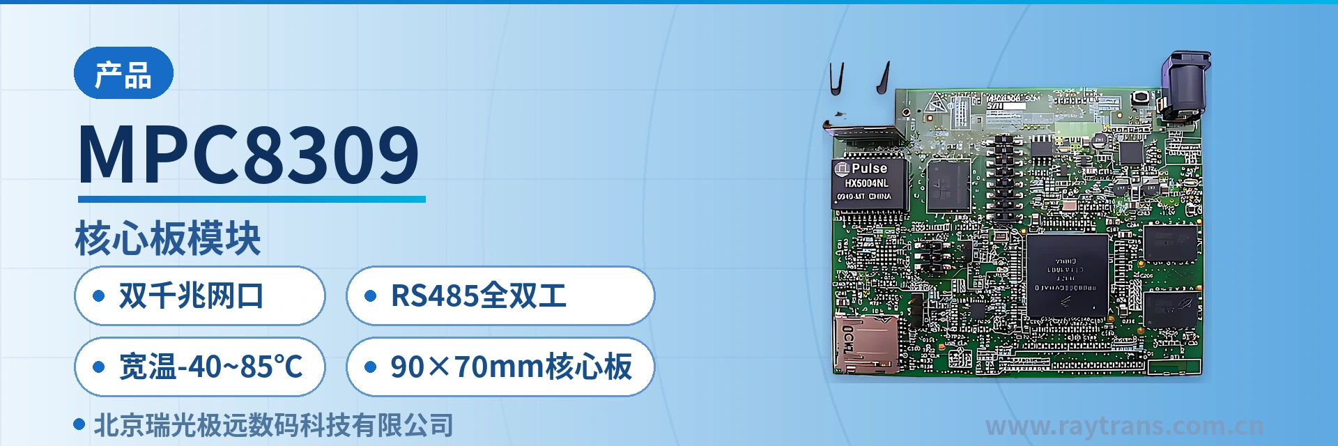
MPC8309 Core Board Module
Three SoCs interchangeable on the same baseboard; dual gigabit Ethernet ports and RS485 full-duplex shipped with the board; schematics provided
Available for order on freescale.com Schematics, Gerber files and user guide provided Will come with Linux® BSP & drivers MQX port will be available mid-August 2010 MPC8308, MPC8306 and MPC8309 SOMs a
The MPC8309 core board module is an industrial-grade core board module designed by Raytrans based on the MPC8308 SoC of the Freescale PowerQUICC™ II Pro series. It targets the complete-unit development of industrial private network communication equipment, electric power and energy remote terminals, and unattended field gateways, and can also be used for the rapid productization and product showcase of products such as bridge converters.
The core board integrates the processor, DDR2 memory, NOR/NAND flash memory, dual RGMII gigabit Ethernet, and an RS485 full-duplex transceiver on a 90×70mm board, so complete-unit manufacturers only need to design the baseboard and structural parts to complete productization. Schematics, Gerber files, and a user guide are provided with the board, together with a Linux BSP and drivers, facilitating the secondary development of industrial private network communication equipment.
Key specifications at a glance: MPC8308 SoC e300 core 400MHz · 256MB DDR2 SDRAM · 8MB NOR + 1GB NAND · dual RGMII gigabit Ethernet ports · RS485 full-duplex transceiver · 90×70mm · wide temperature -40~85℃
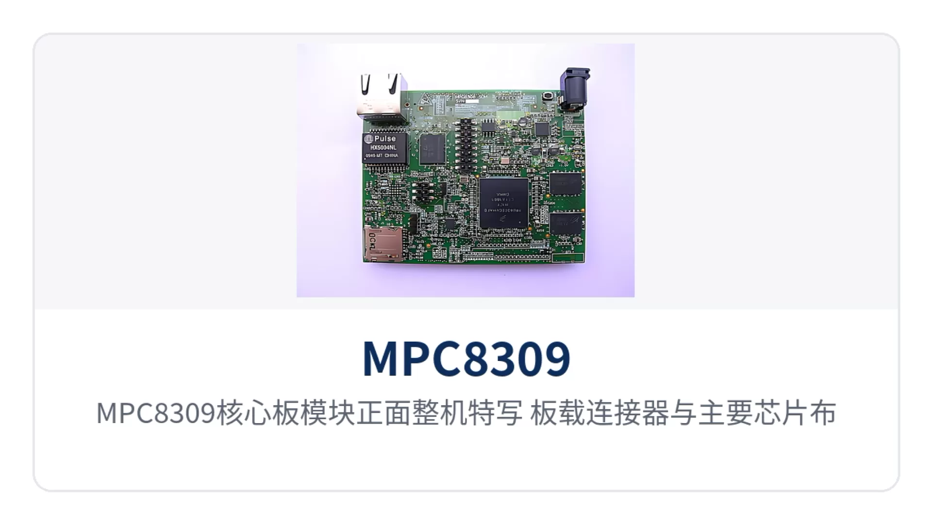
Figure 1: Close-up of the front of the MPC8309 core board module — onboard connectors and main chip layout
What kind of device is the MPC8309 core board module?
A core board module is a pluggable small board that incorporates the processor, memory, storage, and main interface circuits, while complete-unit manufacturers only design the baseboard that carries the power supply and external connectors. The MPC8309 core board module handles computing and communication functions, and the baseboard handles power conversion, interface breakout, and structural assembly. This division of labor fixes high-speed routing on the core board and concentrates complete-unit development on the baseboard, structure, and complete-unit verification, and also makes the hardware solution easier to present in a modular way during the product showcase stage.
The processor of the MPC8309 core board module is the MPC8308, which belongs to the PowerQUICC II Pro series and has an e300 core with a clock speed of up to 400MHz. The product documentation also states that the three core boards MPC8308, MPC8306, and MPC8309 can be used interchangeably with the same baseboard, so one baseboard covers three processing capability tiers and complete units can be selected according to project computing power without redesigning the board. For the documentation package of this type of core board module, Raytrans provides schematics, Gerber files, and a user guide, making it easy for complete-unit manufacturers to quickly implement solutions for industrial private network communication equipment and electric power and energy remote terminals.
What interfaces and functions does the core board provide?
The functions of the MPC8309 core board module are grouped into four sets: computing and storage, networking, serial interfaces, and board-to-board interconnection, each corresponding to a section of actual circuitry in complete-unit design. The table below lists each capability and its implementation by function item, so that when working on a hardware solution you can check row by row which items are already on the board and which need to be placed on the baseboard — particularly suitable for product showcase scenarios such as unattended field gateways that require streamlined peripheral circuits.
| Function | Description |
|---|---|
| Dual RGMII gigabit Ethernet ports | One 10/100/1000Mbps RGMII Ethernet interface is onboard, and the second RGMII is routed out through the board-to-board connector, enabling dual gigabit Ethernet port access at the complete-unit level. |
| RS485 full-duplex transceiver | A full-duplex transceiver is onboard, and the signal is routed out through a DB9 on the baseboard, allowing direct connection to industrial fieldbus devices without an external converter board. |
| 2 UARTs | One RS232 is routed out through a 3-pin header on the board, and the other RS232 is routed out through the board-to-board connector, so local configuration and service serial ports are routed separately. |
| Storage expansion | A Micro-SD card slot is onboard, and a card can be inserted to store configuration, logs, and upgrade packages; on-site card replacement updates the unit without disassembly. |
| USB 2.0 | Supports the Host/Device/OTG roles, routed out through the board-to-board connector and the baseboard, and can connect a USB drive, a serial converter, or a host. |
| Board-to-board interconnection | Through the connector, provides 1 PCIe, Local Bus, USB, the second Ethernet, GPIO and interrupts, RS232 and RS485, and IEEE1588 timing support. |
| Boot mode management | The dynamic boot mode is controlled by the onboard KA2 microcontroller and can switch between boot media such as NOR and NAND, facilitating volume programming and commissioning. |
| Documentation and software delivery | Schematics, Gerber files, and a user guide are provided with the board, together with a Linux BSP and drivers; an MQX port is also available according to the documentation plan. |
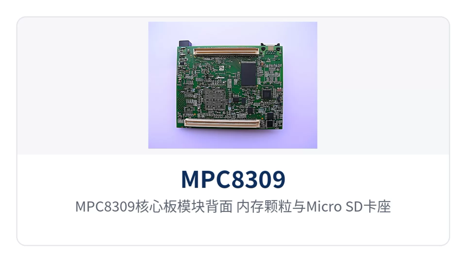
Figure 2: Back of the MPC8309 core board module — memory chips and Micro-SD card slot locations
Technical specifications and interface specifications
The parameters are grouped by computing and storage, interfaces, and power supply environment, and the nominal values follow the product documentation. For on-site verification, the technical documentation provided with the board and the baseboard design shall prevail; for items without values in the table, the confirmation method is noted — check with the manufacturer before placing an order to finalize the configuration. The following specifications also apply as integration references for complete units such as bridge converters and industrial private network communication equipment.
| Item | Parameter/Specification | Description/Applicable Conditions |
|---|---|---|
| Processor | Freescale PowerQUICC II Pro SoC MPC8308 | e300 core, clock speed up to 400MHz |
| Memory | 256MB DDR2 SDRAM | x32-bit interface, 266MHz rate |
| Program storage | 8MB NOR Flash | x16 interface, stores the boot image and firmware |
| Data storage | 1GB NAND Flash | x8 interface, stores the file system and service data |
| Parameter storage | 256Kbit I2C EEPROM | 32Kbit×8, stores board-level parameters and serial information |
| Boot control | KA2 microcontroller | Dynamic boot mode control, switching between boot media |
| Storage expansion | Micro-SD card slot | Onboard slot; insert a card according to on-site capacity requirements |
| Item | Parameter/Specification | Description/Applicable Conditions |
|---|---|---|
| Onboard Ethernet | 1 10/100/1000Mbps RGMII | The gigabit Ethernet port physical interface is on the core board |
| Second Ethernet | RGMII routed out through the board-to-board connector | Forms dual RGMII gigabit Ethernet ports after breakout on the complete-unit side |
| RS485 | Onboard full-duplex transceiver | Routed out through a DB9 on the baseboard, four-wire full-duplex wiring |
| RS232 | 1 3-pin header, 1 board-to-board connector | Configuration port and service serial port routed out separately |
| USB | USB 2.0 Host/Device/OTG | Routed out through the board-to-board connector and the baseboard |
| Expansion bus | PCIe×1, Local Bus, GPIO and interrupts | Channels for peripheral expansion and custom interfaces |
| Timing synchronization | IEEE1588 timing support | Provided through the board-to-board connector, for time synchronization services |
| Item | Parameter/Specification | Description/Applicable Conditions |
|---|---|---|
| Power supply input | 5V @ 1.2A | Can be powered by an external adapter or supplied by the baseboard |
| Board dimensions | 90mm × 70mm | Core board form factor; structural parts are drilled according to these dimensions |
| Operating temperature | -40℃ ~ +85℃ | Industrial wide temperature, suitable for unattended field cabinets |
| Supply method | Orderable at freescale.com | Schematics, Gerber files, and a user guide are provided with the board |
| Software support | Linux BSP and drivers | The MQX port is provided according to the release plan in the product documentation |
| Power consumption margin and certification | not yet recorded in the knowledge base | the manufacturer's technical documentation shall prevail; complete-unit certification is supplemented according to project requirements |
Four capability labels: dual gigabit Ethernet ports, RS485 full-duplex, wide temperature -40~85℃, 90×70mm core board
In on-site discussions, the capabilities of this core board are often summarized in four phrases; for hardware selection, structural design, and procurement interfacing, remember these four terms first. The four labels correspond to network access, fieldbus, environmental adaptability, and structural space respectively. Their boundary conditions and implementation methods are explained one by one below, which also helps quickly align requirements in the product showcase of electric power and energy remote terminals and unattended field gateways.
- Dual gigabit Ethernet ports: one RGMII gigabit Ethernet is routed out directly on the board, and the second is routed to the baseboard through the board-to-board connector, so the complete unit can provide dual-link access — one link for services and one for management or backup — suitable for multi-link networking of devices such as bridge converters.
- RS485 full-duplex: the onboard RS485 full-duplex transceiver supports four-wire full-duplex, so reception and transmission can proceed simultaneously, adapting to fieldbus devices that require duplex interrogation, with one less converter circuit in the periphery.
- Wide temperature -40~85℃: the operating temperature covers -40℃ to +85℃; field cabinets and equipment rooms without air conditioning are selected according to this condition, and the difference between standard-temperature and wide-temperature models lies in component grade.
- 90×70mm core board: the core board form factor is 90mm×70mm; the complete-unit structure reserves installation space accordingly, and the baseboard can be mounted on a DIN rail or embedded in a small volume.
Typical application scenarios
The three industry scenarios share the same characteristics: tight on-site space, a large temperature span, and external interfaces dominated by network ports and serial ports. In these scenarios, the MPC8309 core board module plays the role of the main controller, and the baseboard is adapted to the industry interfaces. The scenario descriptions below focus on deployment conditions and configuration points; the specific configuration is calculated according to project scale.
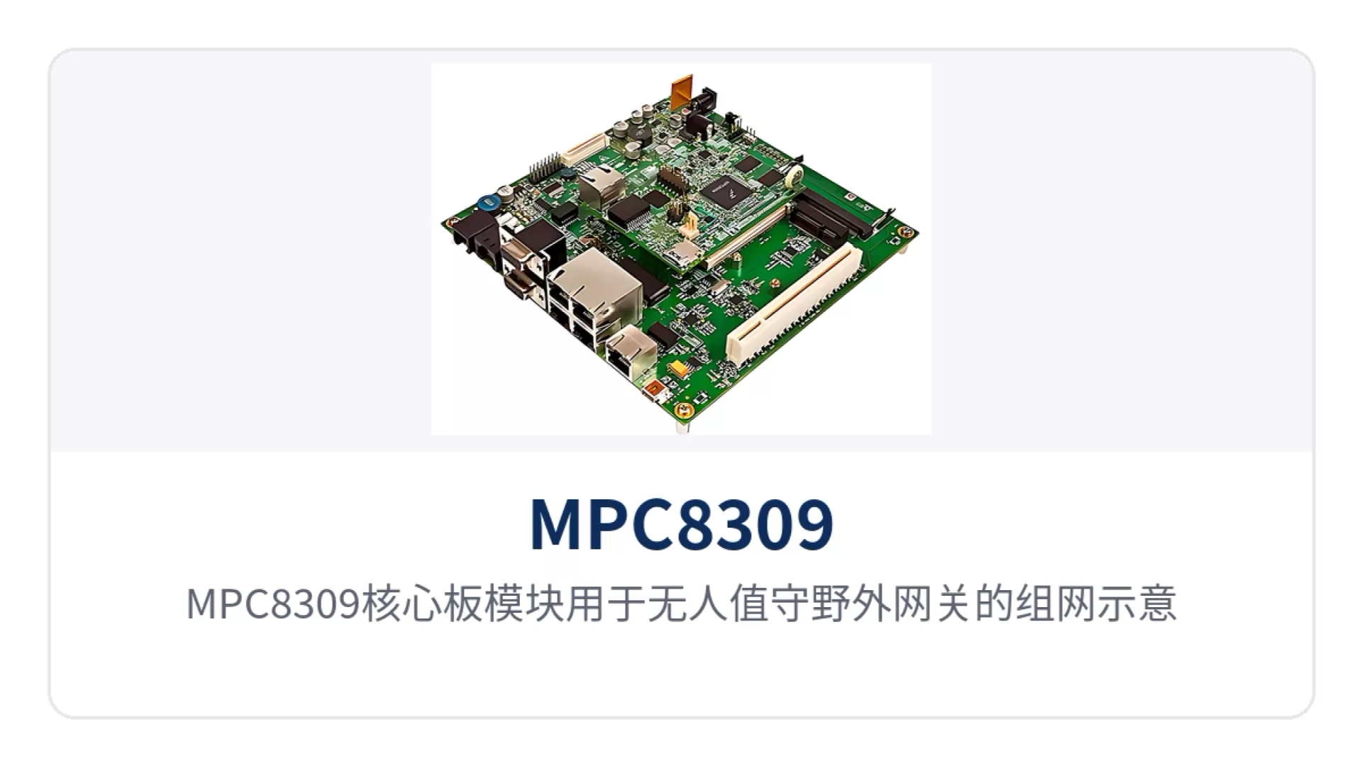
Figure 3: Networking schematic of the MPC8309 core board module used in an unattended field gateway
Industrial private network communication equipment: one baseboard for a dual-port gateway
Complete-unit manufacturers of industrial private network communication equipment often supply gateways, protocol converters, and acquisition terminals in the same project at the same time, and a unified main control solution saves duplicate hardware design and certification work. The MPC8309 core board module provides dual RGMII gigabit Ethernet ports and an RS485 full-duplex transceiver, so one baseboard can complete the common part of these types of complete units, and it is also convenient to complete the product showcase and differentiated configuration on the same platform.
On the baseboard side, only power conversion and connector breakout need to be handled: the 5V input is supplied by an adapter or the baseboard, the two network ports are routed out from the onboard RGMII and the board-to-board connector respectively, and RS485 goes through a DB9. Differences between complete-unit models fall on the baseboard interface combination and the enclosure, so the main control board does not need to be redesigned. For models that require the form of a bridge converter, the baseboard only needs to adjust the interface breakout and enclosure markings to reuse the same main control solution.
Electric power and energy remote terminals: wide temperature and serial ports directly connected to the fieldbus
Electric power and energy remote terminals in substations, photovoltaic power stations, and oil and gas pipelines are mostly installed in outdoor cabinets or unattended small rooms, where cabinet temperatures are high in summer and low in winter; the temperature grade of the main control board directly determines whether the complete unit can pass on-site acceptance. The MPC8309 core board module is designed for an industrial wide temperature of -40℃ to +85℃, covering such in-cabinet environments.
Electric energy acquisition, protection and control, and auxiliary monitoring equipment make extensive use of the RS485 bus; the onboard RS485 full-duplex transceiver can connect directly to the fieldbus, eliminating an external converter board and one more connection point prone to loosening. The 256MB memory and 1GB NAND flash can hold local cache and historical data.
Unattended field gateways: small size and remote upgrade capability
Unattended field gateways are often installed where only a DIN rail slot or a small waterproof box is available, leaving limited area for the main control board, and power is mostly a single 5V or 12V supply. The MPC8309 core board module provides complete computing capability and dual network ports on a 90×70mm board, so the baseboard can be made thinner and the structural parts simpler.
The onboard Micro-SD card slot and 1GB NAND flash memory make it convenient to store configurations, logs, and upgrade packages, and the program can be updated by on-site card replacement. The boot mode managed by the KA2 microcontroller allows production programming and commissioning switching without hardware changes, and the PCIe and Local Bus brought out through the board-to-board connector also leave a channel for adding wireless modules later.
From Core Board to Complete Unit: Carrier Board Design and Commissioning Points
Turning the MPC8309 core board module into a complete unit concentrates the work on three things: carrier board design, power supply verification, and boot commissioning. The actions and judgment criteria are listed below in order; hardware and software can proceed in parallel, but the power supply and boot sequence must be settled before prototyping.
- First define the carrier board interface list: count the network ports, serial ports, USB, and DB9 that the complete unit needs to bring out, and confirm which go through onboard interfaces and which go through the board-to-board connector, avoiding duplicate cabling in two places; if the unit is positioned as a bridge converter, the forwarding path between the two ports also needs to be planned in advance.
- Verify power supply and heat dissipation: the core board takes power at 5V @ 1.2A, and the input can be supplied by an external adapter or the carrier board; the carrier board power supply should leave margin for peak values, and wide-temperature models also need to account for the temperature rise inside the cabinet.
- Open holes according to 90mm×70mm: the mounting hole positions and board-to-board connector positions are taken from the structural documentation supplied with the board, and the connector mating height determines the spacing between the carrier board and the front panel.
- Draw the board-to-board signals clearly in one pass: the second RGMII, PCIe, Local Bus, GPIO and interruption, and RS232/RS485 all go through the connector; cross-board routing is handled as high-speed signals, and length matching and reference planes are arranged at the schematic stage.
- Settle the boot medium and programming method first: the dynamic boot mode is controlled by the onboard KA2 microcontroller; the image layouts of the two boot media, NOR and NAND, differ, so the programming process should be fixed before mass production.
- Bring up the software according to the BSP: first get the serial port and network port running with the Linux BSP and drivers supplied with the board, then verify PCIe and IEEE1588; for projects requiring MQX, confirm the version with the manufacturer according to the release plan given in the product documentation.
- Verify the environment and long-term operation: perform high- and low-temperature power-on tests on the complete unit over the -40℃ to +85℃ range, focusing on the boot success rate and network port link recovery.
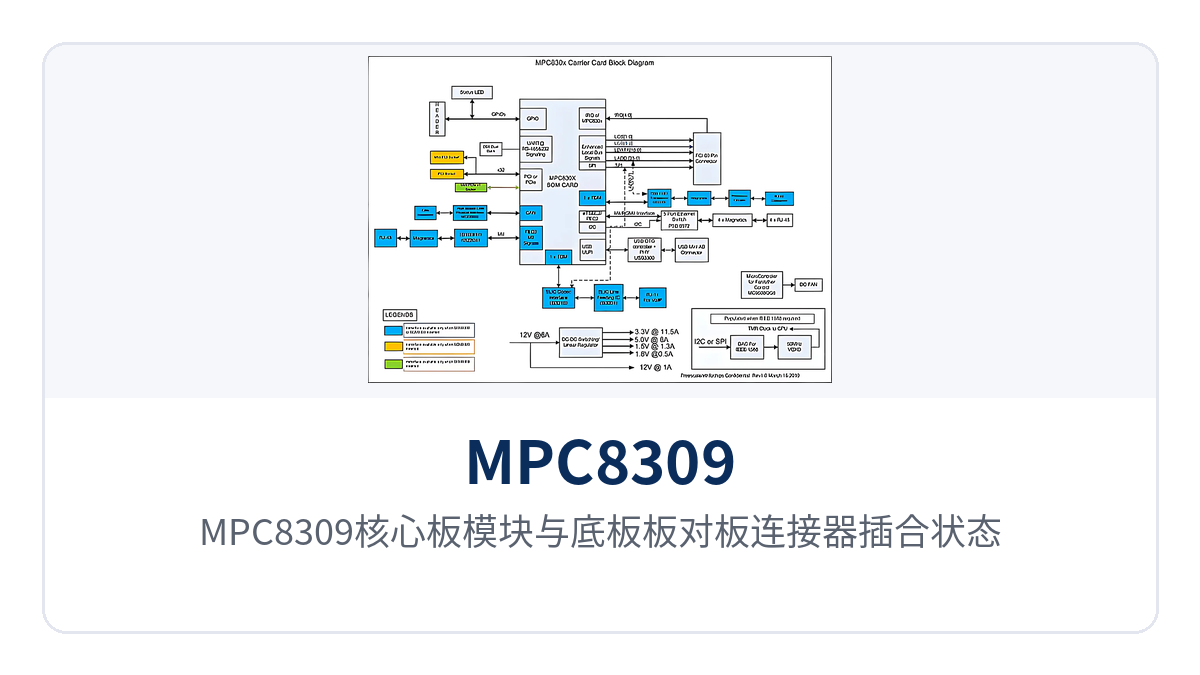
Figure 4: Mating state of the MPC8309 core board module and the carrier board-to-board connector
Conclusion
The MPC8309 core board module packs the computing power of PowerQUICC II Pro, dual RGMII gigabit Ethernet ports, and an RS485 full-duplex transceiver into a 90×70mm board area, with industrial wide-temperature coverage from -40℃ to +85℃, and can serve as a core board module for complete-unit development of industrial private network communication equipment, electric power and energy remote terminals, and unattended field gateways.
The complete-unit manufacturer focuses its effort on the carrier board and structure, while the main control part is delivered as a core board, so both the prototype cycle and the variety of spare parts can be reduced. The same carrier board can also cover the three processing capacity tiers of the MPC8308, MPC8306, and MPC8309, so there is no need to redesign the main control board when the model is extended upward.
During selection, first confirm the project's processing capacity tier, number of network ports, and on-site temperature conditions, then proceed with the carrier board design according to the schematic supplied with the board and the Linux BSP. For power consumption margin and certification level not given in the documentation, follow the criteria confirmed with the manufacturer before ordering, and do not fill them in by industry convention.