IDM WS20 Optical-to-Microwave Conversion
IDU, ODU and antenna integrated, 15G dual STM-1 optical port,
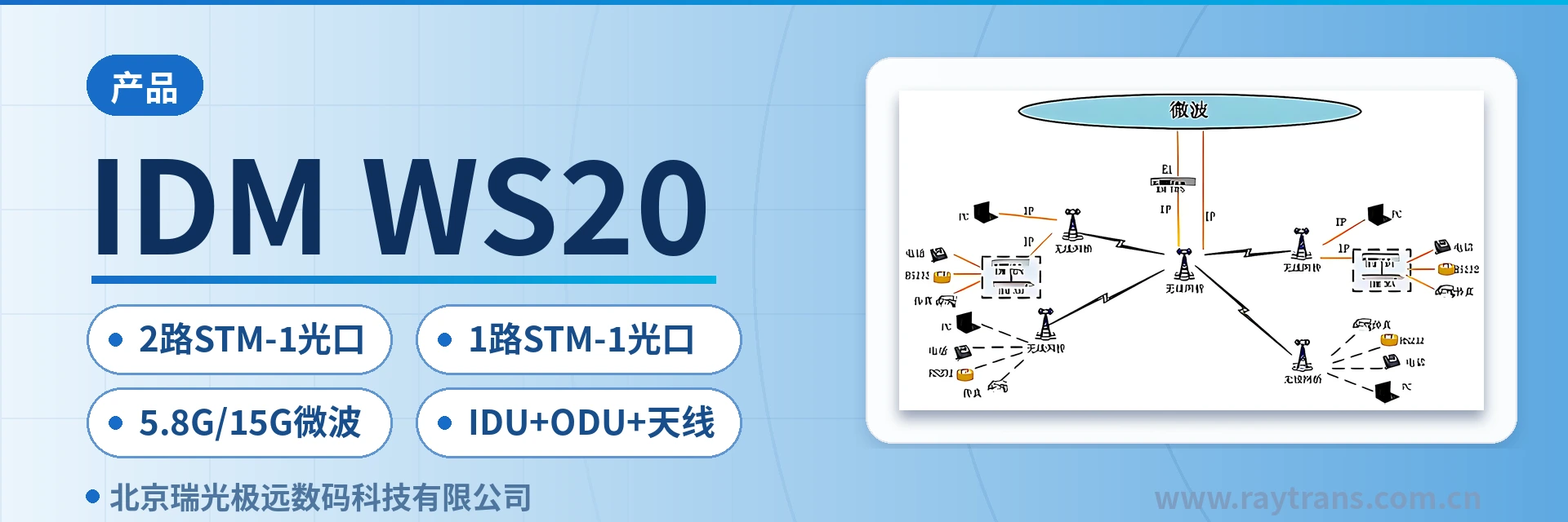
The IDM WS20 consists of an IDU, an ODU and an antenna, and supports conversion from STM-1 optical signals to 5.8G/15G microwave signals. The 15G microwave equipment supports 2 STM-1 optical interfaces, and the 5.8G microwave equipment supports 1 STM-1 optical interface. Wireless bridge and TO
IDM WS20 is an STM-1 optical signal to microwave device, consisting of three parts: the IDU indoor unit, the ODU outdoor unit and the antenna. Developed by Beijing Ruiguang Jiyuan Digital Technology Co., Ltd. (Raytrans), it converts STM-1 optical signals directly into 5.8G or 15G microwave signals, establishing microwave transmission links in sections where optical fiber laying is difficult. It is a typical product showcase of an optical multiplexer manufacturer in wireless supplementary scenarios.
The 15G microwave device supports 2 STM-1 optical interfaces, and the 5.8G microwave device supports 1 STM-1 optical interface; the number of optical paths is selected according to site conditions. Frequency band configuration, service interfaces and installation method are determined by the project list. During selection, first verify the interface forms of the SDH equipment and user services at both ends. As an SDH equipment manufacturer, Raytrans can assist with interface verification and networking design.
Key Specifications at a Glance: 15G microwave, 2 STM-1 optical ports · 5.8G microwave, 1 STM-1 optical port · direct conversion of STM-1 optical signals to 5.8G/15G microwave · IDU + ODU + antenna integrated design · IP port interfacing with an 802.11n wireless bridge · E1 port interfacing with TOP8 equipment
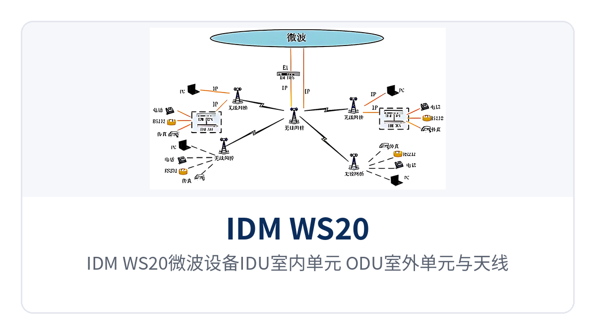
Figure 1: Close-up of the overall appearance of the IDM WS20 microwave equipment combining the IDU indoor unit, ODU outdoor unit and antenna
What Parts Make Up an STM-1 Optical Signal to Microwave Device?
The IDU indoor unit, ODU outdoor unit and antenna are the three parts of the IDM WS20. The indoor side provides access for the STM-1 optical interface and service interfaces, while the outdoor side performs microwave receive/transmit, with the antenna mounted on a tower or pole and aimed in the line-of-sight direction. The IDM WS20 is an IDU + ODU + antenna integrated microwave device; the three parts are supplied as a set following an integrated approach, so the site side no longer needs to select and rack the optical multiplexer, microwave transceiver and antenna separately. As a professional SDH equipment manufacturer, Raytrans (Raytrans) clearly positions this model in its product showcase as a microwave transmission device for private network scenarios.
The value of the integrated design shows in the number of devices and the amount of construction work at field sites. The traditional approach requires an optical multiplexer for the optical interface and a transceiver for the microwave inside the equipment box, plus separate installation of the antenna and feeder, with space, power supply circuits and grounding bars all reserved with margin. The IDM WS20 incorporates the conversion from STM-1 optical signals to 5.8G/15G microwave signals into one set of equipment, so only one mounting position is needed in the cabinet for the IDM WS20, reducing duplicate investment in SDH equipment and supporting devices from optical multiplexer manufacturers.
What Services Can One Microwave Device Connect?
The service capability of the IDM WS20 follows three paths: the optical path side connects to the STM-1 optical interface of SDH equipment, the IP port side connects to a wireless bridge, and the E1 port side connects to TDM Over IP equipment. The three paths can be combined according to the site service list. The functions and their corresponding roles are shown in the table below.
Function | Description |
|---|---|
IDU + ODU + antenna integration | The indoor unit, outdoor unit and antenna form one set of equipment, so field sites do not need to stack multiple single-function devices |
STM-1 optical signal to microwave | Supports conversion of STM-1 optical signals to 5.8G/15G microwave signals, with the optical path side directly interfacing with the optical interface of SDH equipment |
15G dual optical port access | The 15G microwave device supports 2 STM-1 optical interfaces, so a single station can access two optical paths at the same time, saving equipment and optical fiber resources at field sites |
5.8G single optical port access | The 5.8G microwave device supports 1 STM-1 optical interface, configured according to the actual number of optical paths at the site |
IP port interfacing with a wireless bridge | The IP port interfaces with an 802.11n wireless bridge to provide short-distance wireless Ethernet coverage |
E1 port interfacing with TOP equipment | The E1 port interfaces with TOP (TDM Over IP) series equipment to carry various services on E1 lines |
64 kbit/s service access | Multiplexed through TOP4 and PCM equipment to access 64 kbit/s services such as telephone, fax and RS232 |
The two service paths in the table correspond to two types of on-site requirements. Ethernet services go through the IP port and are terminated directly at the user's network equipment by the 802.11n wireless bridge, suitable for short-distance star scatter coverage; 64 kbit/s services such as telephone, fax and RS232 go through the E1 port, where the TOP equipment first converts the E1 bearer to an IP channel, and then the TOP4 and PCM equipment at the coverage point multiplex out voice channels and data ports.
What Is the Difference in Optical Port Configuration Between the 15G and 5.8G Microwave Devices?
The difference between the two frequency band versions centers on the number of STM-1 optical interfaces. The 15G microwave device provides 2 STM-1 optical ports, suitable for a station that needs to access two optical paths at the same time; the 5.8G microwave device provides 1 STM-1 optical port, suitable for a single optical path plus wireless Ethernet coverage. Both perform the conversion of STM-1 optical signals to microwave signals, and the difference lies only in the optical path side capacity.
Frequency band version | STM-1 optical interface | Typical Use |
|---|---|---|
15G microwave device | 2 STM-1 optical ports | Dual optical path access at a single station; two STM-1 optical signals are transmitted over one set of microwave equipment, saving site equipment and optical fiber resources |
5.8G microwave device | 1 STM-1 optical port | Single STM-1 optical signal to microwave, working with an 802.11n wireless bridge for short-distance wireless Ethernet coverage |
Count the optical paths first, then determine the frequency band. When the site side needs to access two independent STM-1 optical paths, select the 15G version with the 2 STM-1 optical interface configuration, avoiding the need for another microwave device for the second optical path; when there is only one optical path and a group of Ethernet terminals also needs coverage on site, the 5.8G version with the single optical port configuration plus a wireless bridge is a better fit. Frequency band use and hop distance conditions must be calculated according to the local frequency license and link budget.
Key Specifications
The model, signal conversion and interface capabilities of the IDM WS20 are verified item by item per project. The table below lists the items already given in the product documentation, covering equipment composition, number of optical interfaces, the purpose of the IP port and E1 port, and the service types that can be carried. Items not listed are subject to the manufacturer's technical documentation and commercial confirmation; do not fill in the engineering configuration sheet based on assumptions.
Item | Parameter/Specification | Description/Applicable Conditions |
|---|---|---|
Device Model | IDM WS20 | Microwave transmission equipment |
Equipment Composition | IDU indoor unit, ODU outdoor unit, antenna | The three parts form one complete set of equipment |
Signal Conversion | STM-1 optical signal to 5.8G/15G microwave signal | The optical path side interfaces with the optical interface of SDH equipment |
STM-1 Optical Interface (15G) | 2-channel | A single station can access dual optical paths |
STM-1 Optical Interface (5.8G) | 1-channel | Single optical path access |
IP Interface | Interfacing with 802.11n wireless bridge | Provides short-distance wireless Ethernet coverage |
E1 Interface | Interfacing with TOP8 equipment | Networking with TOP16, TOP8, TOP4 and TOP2 series |
Carried Services | Ethernet service, telephone, fax, RS232 and other 64 kbit/s services | Telephone, fax and RS232 are multiplexed and accessed via TOP4 and PCM equipment |
Power Supply Mode, Overall Power Consumption, Operating Temperature, Enclosure Dimensions | Not yet recorded in the knowledge base | Subject to the manufacturer's technical documentation and commercial confirmation |
How Are Wireless Bridges and TOP Equipment Connected? Remote Networking Approach
Remote access is organized by division of labor: wireless bridges terminate Ethernet, and TOP equipment terminates 64 kbit/s services. Point-to-multipoint 802.11n wireless bridge equipment forms a star-shaped scatter network and directly accesses the user's Ethernet services; telephone, fax and RS232 services are carried by TOP equipment, sent to each coverage point over the wireless bridge, and then demultiplexed. On-site access can be implemented in the following order:
Master station side: the E1 port of IDM WS20 connects to TOP8 equipment, converting the 64 kbit/s services on the E1 line to IP bearer.
Master station side: the IP port of IDM WS20 connects to the 802.11n wireless bridge, establishing wireless links pointing to each coverage point.
Coverage point: after the wireless bridge terminates, it connects to the user's Ethernet equipment to directly enable Ethernet services.
Coverage point: after the wireless bridge terminates, it connects to TOP4 equipment, which is then multiplexed via PCM equipment to break out telephone, fax and RS232 interfaces.
The value of this link lies in carrying the two types of services separately without building the network twice. Ethernet services pass through the wireless bridge directly and do not need to detour through E1 conversion; 64 kbit/s services are carried by TOP series equipment (TOP16, TOP8, TOP4, TOP2) selected by capacity, with TOP8 used for interfacing with the E1 port and TOP4 plus PCM equipment multiplexing used at coverage points. Once the number of service interfaces and the site distribution are determined, the number of sectors and the coverage radius of the wireless bridge can be calculated.
Typical Application Scenarios
Electric Power and Energy Private Network
Sections between substations, switching stations and dispatch sites often encounter difficulties in optical cable laying and long approval cycles for crossing railways and rivers. IDM WS20 directly converts STM-1 optical signals to microwave, extending the optical interface of SDH equipment to the opposite-end site; the 2-channel STM-1 optical interfaces of the 15G microwave equipment allow one station to access two optical paths simultaneously.
No additional equipment is needed for the second optical path; the dispatch telephone, telecontrol data and video surveillance services at the site can be accessed via the optical path or through the IP port and E1 port according to on-site conditions. The microwave link serves as a supplementary channel for fiber sections; before project implementation, calculate the link margin according to the hop distance and confirm the frequency use conditions. Raytrans can, in conjunction with the overall planning of the government private network optical fiber communication solution, incorporate such microwave transmission links into a networking design where optical cable and wireless complement each other.
Rail Transit Communication Along the Line
Stations, depots and section equipment points along a rail transit line are scattered, and the construction window for trackside cabling is limited. IDM WS20 is deployed point by point, using microwave transmission links to replace section optical cables; the IDU indoor unit is placed in the communications equipment box, and the ODU outdoor unit and antenna are mounted on towers, reducing trackside work.
Coverage points along the line then use 802.11n wireless bridges for short-distance scatter coverage, so that Ethernet services on platforms and at inspection work faces can be accessed nearby. Telephone and RS232 data are multiplexed by TOP equipment and backhauled over the microwave link; the site equipment room only needs to provide an installation position and power supply conditions.
Oilfields and Mining: Field Private Networks
Oilfield well sites, oil pumping stations and mining area sites are distributed in the field, with large spacing between stations and no fixed equipment room. The IDU + ODU + antenna integrated form of IDM WS20 suits such sites: only one installation position is needed in the equipment box, and the antenna is mounted in the line-of-sight direction. Well site Ethernet data is backhauled via the IP port and the wireless bridge, while pithead telephone and instrument RS232 data are carried via the E1 port connected to TOP equipment; the two types of services run in parallel over the same microwave link. For sites requiring rapid deployment, this equipment form can also be used in the military emergency communications vehicle solution, with the antenna mounted on a vehicle-mounted lifting mast to quickly establish a microwave transmission link without a fixed equipment room.
How to Select and Deploy?
Selection determines the configuration based on three items: the number of optical paths, the service types and the site conditions. The number of optical paths determines whether to choose the 2-channel STM-1 optical interfaces of the 15G version or the 1-channel STM-1 optical interface of the 5.8G version; the service types determine whether TOP equipment and PCM equipment are required; and the site conditions determine the antenna mounting height and installation method. As a professional SDH equipment manufacturer, Raytrans recommends checking the following list item by item before implementation:
Optical path side: check the optical interface rate and interface form of the SDH equipment at both ends, and confirm that they correspond to the STM-1 optical interface of IDM WS20.
Service side: list the actual number of channels for Ethernet, telephone, fax and RS232, and select models such as TOP8 and TOP4 according to capacity.
Site side: confirm the installation position on the tower or mounting pole, the line-of-sight conditions and the installation position in the equipment box.
Power supply and lightning protection: the power supply mode and protection configuration are subject to the manufacturer's technical documentation and commercial confirmation; perform grounding according to on-site specifications during construction.
Summary
IDM WS20 is an STM-1 optical signal to microwave device with an integrated IDU + ODU + antenna design; the 15G microwave equipment uses 2-channel STM-1 optical interfaces to achieve dual optical path access at a single station, while the 5.8G microwave equipment uses a 1-channel STM-1 optical interface together with an 802.11n wireless bridge to provide short-distance wireless Ethernet coverage.
On the service side, the IP port and E1 port interface with the wireless bridge and TOP equipment respectively, accessing Ethernet, telephone, fax and RS232 services. For electric power and energy private networks with difficult fiber laying, rail transit communication along the line, and oilfield and mining field private network sites, the configuration can be determined according to the number of optical paths and the service list; specific parameters and frequency use conditions are subject to confirmation in the manufacturer's technical documentation.
⚠️ File-mutation verifier: 1 file edit(s) FAILED this turn despite any wording above that may suggest otherwise. Run git status or read_file to confirm what actually landed. • /home/ubuntu/rag-cms/refs/draft-channel-idm-ws20-master-2026-10-17.md — [write_file] Refusing to overwrite /home/ubuntu/rag-cms/refs/draft-channel-idm-ws20-master-2026-10-17.md: /home/ubuntu/rag-cms/refs/draft-channel-idm-ws20-master-2026-10-17.md was modified by …