
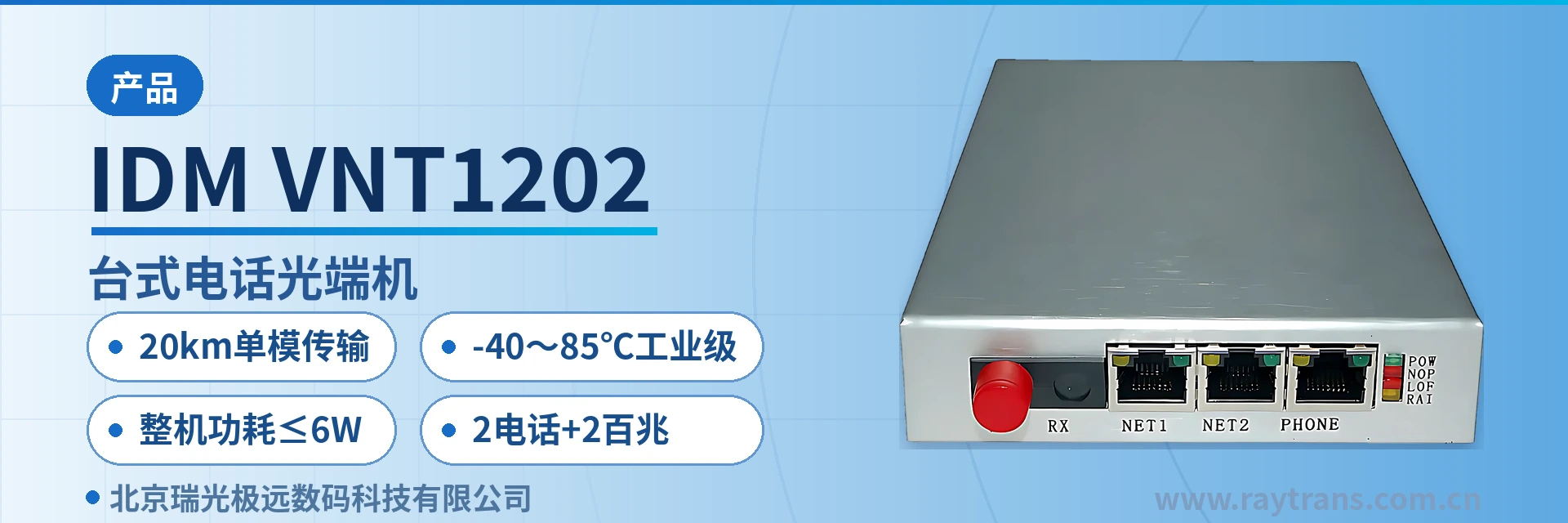
IDM-VNT1202 Desktop Telephone Optical Multiplexer
Video, Telephone, and Ethernet Single-Fiber Multiplexing, Desktop Rack-Free, AC/DC Dual Power Supply
The IDM-VNT1202 multi-service optical multiplexer adopts advanced all-digital uncompressed video transmission technology for high-quality video transmission. It provides 1 bidirectional video, 2 telephone, and 2 Ethernet services.
IDM-VNT1202 desktop telephone optical multiplexer is a desktop video telephone optical multiplexer that multiplexes video, telephone, and Ethernet services onto a single optical fiber. It is developed by optical multiplexer manufacturer Beijing Ruiguang Jiyuan Digital Technology Co., Ltd. and is used for multi-service backhaul at electric power private networks, rail transit communication, oil and gas pipelines, and unattended mining sites. It can also serve as an access device in smart mining communication solutions and government private network optical fiber communication solutions.
The device adopts all-digital uncompressed video transmission technology and comes standard with 1 bidirectional video channel, 2 telephone channels, and 2 Fast Ethernet channels. After a single fiber enters the device, it is split into three types of service channels, and the peer end restores the BNC video port, telephone ports, and RJ-45 Ethernet ports, so on-site video, dispatching calls, and the office network can be transmitted over the same cable. As a multi-service optical multiplexer, it carries video, voice, and data services simultaneously on one device, and product showcases often highlight its rich interfaces and simple deployment.
A field site rarely handles just one service: surveillance needs to backhaul video, the duty room needs telephone calls, and office and acquisition devices need network connectivity. When the three service types are cabled separately and configured with separate transmission devices, rack positions and optical fiber resources in the equipment box quickly run out. IDM-VNT1202 consolidates these interfaces into a 110mm×168mm×28mm desktop chassis; connect the optical patch cord and service cables and it is ready to work. For scenarios requiring video backhaul, this video optical multiplexer can directly connect to surveillance cameras; for sites mainly using voice dispatching, its telephone optical multiplexer function meets duty call requirements.
Key Specifications at a Glance: 1 bidirectional video channel (all-digital uncompressed) · 2 telephone channels (ITU G.711 A-law) · 2 Fast Ethernet channels (IEEE802.3 adaptive) · 155M optical interface · 20km single-mode transmission · receiver sensitivity better than -32dBm · -40~85℃ industrial-grade · overall power consumption ≤6W · AC220V/DC-48V
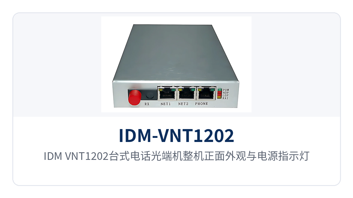
Figure 1: Front view of the IDM-VNT1202 desktop telephone optical multiplexer with close-up of power indicator LED and optical link indicator LED
What Is a Desktop Video Telephone Optical Multiplexer
A desktop video telephone optical multiplexer is a desktop device that consolidates video, telephone, and Ethernet services into point-to-point transmission over a single fiber. It is used in pairs, with one end connecting to cameras, telephones, and switches, and the other end restoring the corresponding BNC video port, telephone ports, and RJ-45 Ethernet ports. As a representative product showcase from optical multiplexer manufacturer Raytrans, this type of desktop device further integrates the multiplexing capability of a multi-service optical multiplexer on the basis of video optical multiplexers and telephone optical multiplexers.
IDM-VNT1202 is designed along these lines: video is sent directly onto the optical path in an all-digital uncompressed manner, telephone is encoded in ITU G.711 A-law, Ethernet is multiplexed as a 10M/100M adaptive channel, and the three service types share a single 155M optical channel. Service is activated once both ends are configured as a pair.
Compared with ordinary optical multiplexers that only transmit video, the difference lies in service types and interface count. IDM-VNT1202 comes standard with 1 bidirectional video channel, 2 telephone channels, and 2 Fast Ethernet channels. Bidirectional video allows the dispatch-side picture to be sent back to the site, so the site and the dispatch side see the same signal. The 2 telephone channels are transmitted over an audio range of 300Hz~3400Hz, use ITU G.711 A-law compression, and provide a loop current of 25mA per channel; calls are available once a telephone or switching equipment is connected.
The video section preserves picture quality by not performing compression encoding. Video signals enter the optical channel with 8bit sampling and 0Hz~6.5MHz bandwidth, eliminating the latency and loss of detail from the encoding and decoding process, with differential phase better than 0.7°, differential gain better than 0.7%, and video SNR ≥70dB (weighted). The picture from the camera retains its original clarity on the monitor, making it suitable for unattended sites where equipment meter readings and personnel actions must be clearly seen.
The unit uses a desktop structure with dimensions of 110mm×168mm×28mm. It can be placed directly on a duty desk, an equipment box shelf, or a small cabinet tray without occupying 19-inch rack space. Power supply supports both AC220V and DC-48V, and overall power consumption is ≤6W. The existing DC power distribution panel in a communications equipment room can supply power directly, so the site does not need to add a separate power supply module or cooling measures for this device.
What Services Can One IDM-VNT1202 Support
The service interfaces of IDM-VNT1202 are standard in three groups: video, telephone, and Ethernet, with data and high-fidelity audio channels available as project options. The functions and corresponding interface forms are listed in the table below for item-by-item verification against the site service list. The parameters in the table are taken from the original product documentation; the specific configuration is subject to the order list and manufacturer's documentation.
| Function | Description |
|---|---|
| All-digital uncompressed video transmission | Video signals are sent directly into the optical channel without compression encoding, avoiding encoding and decoding latency and picture quality loss caused by compression |
| 1 bidirectional video input | BNC interface, 75Ω unbalanced, 8bit sampling, video bandwidth 0Hz~6.5MHz, input/output 1VP-P (typical) |
| 2 telephone inputs | Audio range 300Hz~3400Hz, ITU G.711 A-law compression, loop current 25mA per channel |
| 2 Fast Ethernet channels | RJ-45 interface, 10M/100M adaptive, compliant with IEEE802.3, full/half duplex/adaptive |
| Optional data channel | RJ-45 interface, supports RS-232, RS-422 (4-wire), RS-485 (2-wire), used for PTZ control and status backhaul |
| Optional high-fidelity audio | RJ45 interface, audio sampling bit width 16bit, sampling frequency 32KHz, SNR ≥90dB, total harmonic distortion <1% |
| Optional service combinations | Video, telephone, Ethernet, data, and audio combined according to the on-site service list; see the optional configuration table |
| Single-core optical channel multiplexing | Receive/transmit rate 155M/155M, single-mode 1310nm/1550nm wavelength pairing, all services share one fiber |
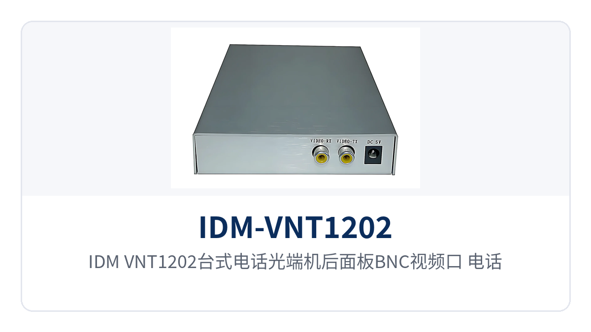
Figure 2: Close-up of the rear panel of the IDM-VNT1202 desktop telephone optical multiplexer showing BNC video port, telephone interfaces, and two RJ-45 Ethernet ports
What is often overlooked in the function table is the two optional channel types: data and audio. PTZ control, access control, and device status acquisition run over RS-232, RS-422 (4-wire), or RS-485 (2-wire), so no additional pair of cables is needed for these low-speed signals during on-site upgrades. The high-fidelity audio channel is suitable for PA, announcements, and on-site monitoring; its 20Hz~20KHz bandwidth covers the audible frequency range of the human ear, and the distortion of restored sound is less than 1%. In its multi-service optical multiplexer product showcases, Raytrans also presents such interface combinations as common configurations for smart mining communication solutions and government private network optical fiber communication solutions, making it easy for users to flexibly match them to actual site services during network planning and selection.
Technical Specifications: How to Verify Optical Interface, Video, Telephone, and Ethernet
Technical specifications are listed in five groups: optical interface, video interface, telephone and high-fidelity audio, Ethernet and data, and power and environment. The optical and electrical ends are used in pairs, and the rate and wavelength at both ends must be paired. Engineering verification starts with the receive/transmit wavelength and transmission distance of the optical interface, then checks whether the number of service interfaces covers the on-site list, and finally verifies the power supply mode and installation space. As an optical multiplexer manufacturer, Raytrans presents the parameters of telephone optical multiplexers, video optical multiplexers, and multi-service optical multiplexers separately in its product showcases, making item-by-item comparison easy during selection.
Optical Interface Parameters
| Item | Parameter/Specification | Description/Applicable Conditions |
|---|---|---|
| Interface type | FC (SC and others customizable) | Optical patch cord interface selected according to the on-site optical cable termination method |
| Fiber mode | Single-mode (multimode optional) | 20km single-mode transmission configuration; multimode confirmed per project |
| Receiver receive/transmit rate | 155M/155M | 155M optical interface, same rate at both ends |
| Receiver receive/transmit wavelength | 1310nm/1550nm | Single-fiber bidirectional transmit and receive dual-wavelength pairing |
| Transmitter receive/transmit rate | 155M/155M | 155M optical interface, same rate at both ends |
| Transmitter receive/transmit wavelength | 1550nm/1310nm | Cross-paired with the peer wavelength |
| Transmit optical power | -15~-8dBm | Available optical power range at the transmit side |
| Receiver sensitivity | Better than -32dBm | Lower limit of available optical power at the receive side |
| Transmission distance | 20Km | Long-distance optical module can be optionally installed for longer optical fiber transmission |
The optical link is the calculation basis for the entire service. The margin between the transmit optical power of -15~-8dBm and the receiver sensitivity of better than -32dBm is the link budget space. The actual achievable distance must also deduct optical cable loss and the number of splice points and flanges. In engineering practice, it is recommended to reserve a certain margin at both ends to avoid insufficient received optical power after optical cable aging or end face contamination. Whether for a telephone optical multiplexer or a video optical multiplexer, the optical interface pairing principle is the same.
Video Interface Parameters
| Item | Parameter/Specification | Description/Applicable Conditions |
|---|---|---|
| Interface type | BNC | 75Ω unbalanced video interface |
| Video sampling bit width | 8bit | All-digital uncompressed sampling |
| Video bandwidth | 0Hz~6.5MHz | Covers standard-definition video signal bandwidth |
| Luminance non-linearity | <3% | Picture luminance distortion specification |
| Differential phase (DP) | <0.7° | Color signal phase distortion specification |
| Differential gain (DG) | <0.7% | Color signal amplitude distortion specification |
| Input overload voltage | 1.5VP-P (typical) | Protection margin at the input side |
| Input/output voltage | 1VP-P (typical) | Standard video level |
| Input/output impedance | 75Ω (unbalanced) | Consistent with cameras and display devices |
| Video SNR | ≥70dB (weighted) | Reflects picture noise level |
Among video specifications, SNR, differential phase, and differential gain determine how the picture looks over a long link. A video SNR of ≥70dB (weighted) means background noise in the picture is not noticeable; differential phase and differential gain are both better than 0.7, so color edges do not show obvious color cast or chroma saturation jumps. This meets interpretation requirements when reading meter values or identifying personnel actions. The picture quality of a video optical multiplexer is directly reflected by this group of specifications.
Telephone and High-Fidelity Audio Parameters
| Item | Parameter/Specification | Description/Applicable Conditions |
|---|---|---|
| Telephone audio range | 300Hz~3400Hz | Telephone voice bandwidth |
| Telephone impedance | Three-element complex impedance 200Ω+560Ω//0.1μF | Matches SPC exchange and telephone side |
| Compression | ITU G.711 A-law | Voice encoding method, interoperable with mainstream switching equipment |
| Loop current | 25mA per channel | Power feeding current per telephone channel |
| High-fidelity interface type | RJ45 | Audio access interface |
| Audio sampling bit width | 16bit | Sampling precision for high-fidelity service |
| Input/output impedance | ADC:100KΩ/DAC:10KΩ | Audio input/output impedance |
| Input/output voltage | 1.5VP-P (typical) | Audio level |
| Audio sampling frequency | 32KHz | Sampling rate for high-fidelity service |
| Audio SNR | ≥90dB | Reflects audio channel noise level |
| Audio bandwidth | 20Hz~20KHz | Covers the audible frequency range of the human ear |
| Total harmonic distortion | <1% | Distortion of restored sound |
The interoperability of telephone channels depends on two items: encoding and impedance. ITU G.711 A-law is the common encoding of domestic telephone networks; the three-element complex impedance of 200Ω+560Ω//0.1μF matches the SPC exchange and ordinary telephone side, and the loop current of 25mA per channel ensures normal power feeding to the telephone. On site, connecting a telephone directly across the telephone port enables calls without additional power feeding equipment. The voice channel interoperability of a telephone optical multiplexer is verified on this basis.
Ethernet and Data Interface Parameters
| Item | Parameter/Specification | Description/Applicable Conditions |
| --- | --- | --- | --- |
| Ethernet interface type | RJ45 connector | 2-channel Fast Ethernet port |
| Ethernet transmission rate | 10M/100M adaptive | Auto-negotiation based on access network rate |
| Standard protocol | Supports IEEE 802.3 | Compatible with general Ethernet devices |
| Operating mode | Adaptive half-duplex/full-duplex | Negotiated with the opposite-end switch |
| Data interface type | RJ45 connector | Optional data channel |
| Data type | RS-232, RS-422 (4-wire), RS-485 (2-wire) | Optional per on-site control device interface |
The 2-channel Fast Ethernet operates per the IEEE 802.3 standard, with 10M/100M adaptive and adaptive half-duplex/full-duplex; once connected to an ordinary switch or network camera, communication works without changing configuration at either end. For sites that need to separate the office network from the video network, the two Ethernet channels can connect to different switches, with each service forming an independent channel over the optical fiber; the multi-service optical multiplexer transmits video, telephone, Ethernet and data channels over the same pair of optical multiplexers.
Power Supply, Power Consumption, Environmental and Structural Parameters
| Item | Parameter/Specification | Description/Applicable Conditions |
|---|---|---|
| Power supply mode | AC 220 V/DC -48 V | Direct power supply access at both AC sites and DC communications equipment rooms |
| Overall power consumption | ≤6 W | Less power supply access and heat dissipation pressure for long-term online operation |
| Operating temperature | -15℃~+65℃ | Standard equipment room and equipment box environment |
| Storage temperature | -25℃~+75℃ | Warehousing and transportation environment |
| Industrial grade | -40℃~+85℃ | Industrial-grade wide-temperature configuration, suitable for harsh on-site conditions |
| Relative humidity | 0~95% (non-condensing) | Applicable condition in high-humidity environments is non-condensing |
| Product dimensions | 110 mm×168 mm×28 mm (Length×Depth×Height) | Desktop structure, flexible installation position |
The environmental and power supply items determine whether the device can stay long-term at an unattended site. The industrial-grade wide-temperature configuration covers -40℃~+85℃ and relative humidity 0~95% (non-condensing), covering outdoor equipment boxes, pole-mounted enclosures and factory buildings with large temperature fluctuations; the standard operating temperature of -15℃~+65℃ and storage temperature of -25℃~+75℃ are used for cross-checking against equipment rooms and indoor equipment boxes. Raytrans optical multiplexers are selected and configured per the above environmental and power supply conditions in smart mining communication solutions and government private network optical fiber communication solutions.
Optional Configurations: Interface Combinations Determined by the On-Site Service List
Optional functions are determined by the project service list; the same pair of devices can cover combinations ranging from telephone plus network only to video plus data plus audio. Before ordering, list the on-site interface quantities and directions clearly; the specific configuration is subject to the manufacturer's technical documentation and commercial confirmation.
| No. | Brief Description of Optional Functions |
|---|---|
| 1 | 2-channel Fast Ethernet, 2-channel telephone |
| 2 | 1-channel bidirectional video, 1-channel bidirectional data |
| 3 | 1-channel bidirectional video, 1-channel 10M Ethernet, 1-channel telephone, 1-channel bidirectional data, 1-channel bidirectional audio |
| 4 | 1-channel bidirectional video, 1-channel 10M Ethernet, 2-channel telephone, 1-channel bidirectional data, 1-channel unidirectional audio |
The four configurations above correspond to four typical site types. Sites that only need telephone and networking choose the 2-telephone plus 2-Fast-Ethernet combination; sites that only need to view images and control devices choose video plus bidirectional data; where the site needs both images and calls, plus 10M Ethernet, data and audio channels, configuration group 3 or 4 brings all services together in one pass. Raytrans provides selection references for these four combinations in its product showcase; smart mining communication solutions and government private network optical fiber communication solutions can determine the optical multiplexer interface configuration accordingly.
Differentiated Value: 20 km Single-Mode Transmission, Industrial-Grade Wide Temperature, Low Power Consumption and 2 Telephone + 2 Fast Ethernet
As an optical multiplexer product for industry users, the IDM-VNT1202 concentrates its differentiated value in four items: transmission distance, environmental adaptability, power consumption and service composition. Each item corresponds to verifiable specifications, so the parameters in the table below can be copied directly into a technical specification during selection, and the capability specifications and applicable conditions are described item by item for direct citation in design institute selection tables and bid parameter tables.
| Differentiation Point | Corresponding Capability and Specifications | Applicable Conditions and Value |
|---|---|---|
| 20 km single-mode transmission | 20 km over a single fiber, transmit optical power -15~-8 dBm, receiver sensitivity better than -32 dBm, 155M optical interface | One fiber core directly connects adjacent sites, with no repeater or routing/switching equipment; for longer distances, a long-distance optical module is installed |
| -40~85℃ industrial grade | Industrial-grade wide temperature -40℃~+85℃, relative humidity 0~95% (non-condensing) | Usable in field cabinets, outdoor equipment boxes and unattended sites, and also suitable for along-the-line environments with large winter-summer temperature differences |
| Overall power consumption ≤6 W | AC 220 V/DC -48 V dual power supply, overall power consumption ≤6 W | Direct power supply access from DC communications equipment rooms, low power supply pressure at the site, and low heat dissipation burden for long-term online operation |
| 2 telephone + 2 Fast Ethernet | 1-channel bidirectional video, 2-channel telephone, 2-channel Fast Ethernet, plus optional data and audio | One fiber core carries images, calls and network simultaneously, replacing multiple single-function devices and saving both equipment box space and optical fiber resources |
The device works on a 20 km single-fiber link with transmit optical power of -15~-8 dBm and receiver sensitivity better than -32 dBm, so services remain stable even on weak optical links with high optical cable loss or aged connectors. The link budget is calculated per the actual optical cable route, with splice points and fiber adapters counted together in the loss; spare fiber cores are deployed together at the design stage for faster switching during a failure.
The industrial-grade -40~+85℃ wide temperature range is a prerequisite for field deployment. The summer in-cabinet temperature of substation outdoor cabinets, along-the-line equipment boxes and oil and gas pipeline valve chambers is often higher than that of an equipment room, while in winter in the north it may drop below -20℃; transmission devices of ordinary commercial temperature grade tend to work abnormally in such environments. The industrial-grade wide-temperature configuration extends the operating range to -40℃~+85℃ and, together with the 0~95% (non-condensing) humidity condition, covers the common operating conditions of field cabinets.
The direct benefit of overall power consumption ≤6 W is that both power supply and heat dissipation are easy to arrange. AC 220 V/DC -48 V dual power supply is selectable, and the existing DC distribution panel in a communications equipment room can supply power directly without a separate power adapter for this device; ≤6 W means that even during long-term online operation in an unattended box without air conditioning, the enclosure temperature rise is limited, and photovoltaic power supply or small-capacity storage battery sites can also support it.
Typical Application Scenarios
Electric Power Private Network: Images, Dispatch Telephone and Intranet Backhaul over the Same Fiber Between Substations and Power Supply Stations
Between substations and power supply stations there is usually both image surveillance and dispatch and administrative telephone, and the in-station office network also needs to be connected back to the management area. In the past, the three service types each ran on separate channels, occupying more cable and equipment box rack positions and requiring separate troubleshooting during O&M. The IDM-VNT1202 multi-service optical multiplexer multiplexes 1-channel bidirectional video, 2-channel telephone and 2-channel Fast Ethernet onto one fiber core, so in-station images, dispatching calls and the office network are sent from the same device.
Most cabinets at electric power sites have no air conditioning and no permanent staff, and power is mainly supplied at DC -48 V. The device supports AC 220 V/DC -48 V power supply with overall power consumption ≤6 W; the industrial-grade wide-temperature configuration covers -40℃~+85℃ and, together with weak-light adaptability with receiver sensitivity better than -32 dBm, it is suitable for long-term deployment in substation outdoor cabinets and power supply station equipment rooms, so there is no need to frequently visit the site to replace devices after maintenance or the thunderstorm season.
Rail Transit Communication: Centralized Service Access at Along-the-Line Equipment Rooms and Station Duty Rooms
Along-the-line equipment rooms, traction substations and station duty rooms of rail transit are distributed on both sides of the line, with inter-station distances ranging from several hundred meters to more than ten kilometers; equipment room space is tight and most sites are unattended. The IDM-VNT1202, in a desktop enclosure, is installed in a small cabinet or wall-mounted box in the equipment room, and one fiber core sends along-the-line images, section telephone and station network to the nearest station, so there is no longer a separate video optical multiplexer and telephone optical multiplexer for video and telephone.
Bidirectional video is of practical significance for rail transit sites: the dispatch center needs to see on-site device status, and on-site maintenance personnel also need to see the images and prompt information delivered from the dispatch end. The 2-channel telephone can be used separately for section emergency calls and duty calls, and the 2-channel Fast Ethernet can connect one channel to video and one to office or inspection data, with each service independent on the fiber and not crowding out the others.
Oil and Gas Pipeline and Mining Unattended Sites: Long-Term Online Equipment in Field Cabinets
Sites at oil and gas pipeline valve chambers, pumping stations and mining area sites are distributed in the field, with long distances and low frequency of on-site inspection, and a site usually has only one DC power supply and one equipment box. The IDM-VNT1202 matches such sites with three capabilities: industrial-grade wide temperature of -40~85℃, overall power consumption ≤6 W and DC -48 V power supply; one fiber core backhauls valve chamber images, duty telephone and the acquisition network simultaneously to the station control center, and it is also often used as a front-end access device in smart mining communication solutions.
The O&M cost of field sites lies mainly in the round-trip travel, so the simpler the device itself, the better. The desktop enclosure has only one optical port and several service ports with clear wiring relationships, so on-site connection follows the labels; when a link is abnormal, first check the optical link indicator LED, then measure the received optical power with an optical power meter and compare it with the specification of receiver sensitivity better than -32 dBm to determine whether the problem is the device or excessive optical cable loss.
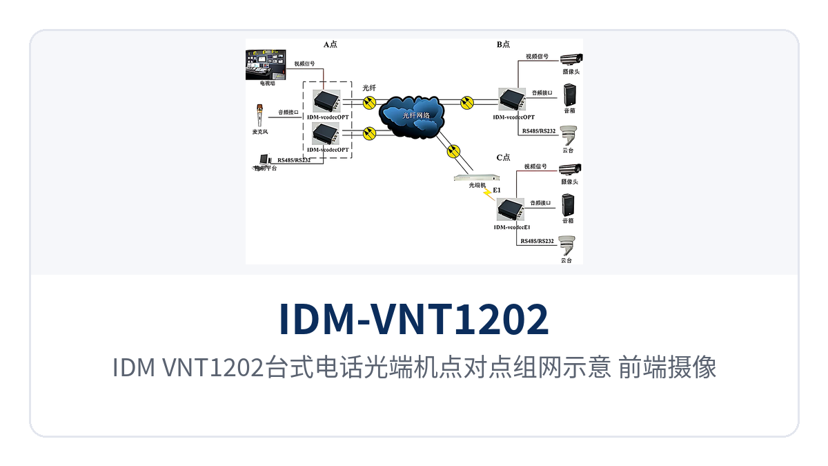
Figure 3: Point-to-point networking diagram of the IDM-VNT1202 desktop telephone optical multiplexer; front-end cameras and telephones access the central duty room over one single-mode fiber
How to Select a Desktop Video Telephone Optical Multiplexer
Selection proceeds from the on-site service list: first determine the service types and channel counts, then the transmission distance and optical module, and finally check the three items of power supply mode, environmental grade and installation space. The four check items and common practices are listed below for item-by-item comparison during the design stage and commercial confirmation, and the configuration can generally be settled in one pass.
- Service types: if the site only needs telephone and network, configure 2-channel Fast Ethernet plus 2-channel telephone; to view images and control devices, configure video plus bidirectional data; if images, calls, network and data are all needed, stack them per group 3 or group 4 of the optional configuration table.
- Video direction: use unidirectional video when only on-site images need to be sent back to the center; use bidirectional video when both ends need to see each other's images; this model comes standard with 1-channel bidirectional video.
- Transmission distance: 20 km single-mode as standard, calculated per the actual optical cable length plus loss margin; when beyond the coverage range, install a long-distance optical module rather than arbitrarily adding a repeater midway.
- Power supply and environment: take AC 220 V in equipment rooms and DC -48 V in communications equipment rooms and field DC sites; for outdoor equipment boxes and factory buildings with large temperature fluctuations, check the industrial-grade wide temperature of -40℃~+85℃ and confirm that an installation position can be found for the 110 mm×168 mm×28 mm enclosure.
How to Deploy On-Site Wiring and Commissioning
Wiring corresponds item by item to service type: video over BNC coaxial cable, telephone over telephone line, Ethernet over network cable, and the optical path over optical fiber patch cord, with both ends in paired configuration and service ports corresponding one to one. The on-site wiring relationships are shown in the table below; before construction, check the interface quantities and directions at both ends, which is also the most basic part of the optical multiplexer product showcase and on-site deployment.
| Service | Equipment-Side Interface | On-Site Connection | Description |
|---|---|---|---|
| Video | BNC, 75 Ω unbalanced | Camera, monitor, video recording device | Input/output direction connected per on-site signal flow |
| Telephone | Telephone interface | Telephone, switching equipment | Audio range 300 Hz~3400 Hz, A-law in ITU G.711 |
| Ethernet | RJ45 connector | Switch, network camera | 10M/100M adaptive, compliant with IEEE 802.3 |
| Data (optional) | RJ45 connector | PTZ controller, access control, acquisition terminal | Wired per RS-232, RS-422 (4-wire), RS-485 (2-wire) |
| High-fidelity audio (optional) | RJ45 connector | PA, announcement and monitoring equipment | Sampling 32 kHz, audio SNR ≥90 dB |
| Optical path | FC (SC and other interfaces can be customized) | Optical fiber patch cord, optical cable | Single-mode 20 km, transmit and receive wavelengths 1310 nm/1550 nm paired |
Follow the six steps below in sequence for commissioning. Confirm that signals are normal at each step before proceeding to the next, so that once all services are enabled you can still tell which segment a point of failure falls in. Recording measured values item by item also makes it easier to compare against the original device state during later inspection, and at shift handover there is no need to work out the wiring relationship between the two ends again.
- Power-on self-test: Connect the AC220V or DC-48V power supply and confirm that the overall power consumption and indicator LED status are normal and that the enclosure does not heat up abnormally.
- Optical path check: Measure the received optical power on the receive side with an optical power meter and compare it against the receiver sensitivity specification of better than -32dBm; confirm that the transmit and receive wavelengths at both ends, 1310nm/1550nm, are paired in a cross configuration.
- Video commissioning: Connect the camera and monitor and check the image for noise, color cast and jitter; if necessary, verify the BNC connectors and 75Ω impedance matching.
- Telephone commissioning: Connect the telephone or switching equipment, go off-hook on each channel and listen, and confirm that ringing, conversation and hang-up release are normal.
- Ethernet commissioning: Connect the switch and confirm that the port 10M/100M adaptive negotiation succeeds; according to the service division, connect the two Ethernet channels to the video network and the office network respectively.
- Record and archive: Register the device numbers at both ends, the received optical power at the optical ports and the correspondence of service ports, as the comparison basis for later inspection.
Conclusion
The IDM-VNT1202 desktop video telephone optical multiplexer packs 1-channel bidirectional uncompressed video, 2-channel telephone and 2-channel Fast Ethernet into a single desktop enclosure, and uses one single-mode fiber to complete 20km point-to-point transmission, with receiver sensitivity better than -32dBm ensuring usability of weak optical links. As a representative model combining the functions of a video optical multiplexer and a telephone optical multiplexer, it can equally serve the role of a multi-service optical multiplexer, and in Raytrans's product showcase it is widely applicable to scenarios such as smart mining communication solutions and government private network optical fiber communication solutions.
The three conditions of industrial-grade -40 to +85℃ wide temperature, ≤6W overall power consumption and ACV220V/DC-48V dual power supply allow this desktop video telephone optical multiplexer to be placed directly in the outdoor cabinet of a substation, the equipment room of rail transit and the equipment box of an oil and gas pipeline valve chamber for long-term online operation. When choosing an optical multiplexer manufacturer, Raytrans's experience in product showcase, optical multiplexer delivery and the implementation of smart mining communication solutions and government private network optical fiber communication solutions also provides reliable support for on-site deployment.


