IDM STM1 Bridge
63-group E1 arbitrary partitioning, 4-channel 100M physically isolated, single unit directly connected to SDH to save one level of coordination
The IDM GE/STM1 is an intelligent aggregation bridge developed in response to customers' high-capacity Ethernet leased-line access requirements. It can aggregate 63 groups of E1 into gigabit Ethernet and directly interconnect with SDH transmission equipment. Channels 1 to 63 can be arbitrarily partitioned according to different bandwidth requirements, and Ethernet data is transparently carried with each channel as a link unit.
An STM-1 Ethernet bridge is an access device that converts SDH STM-1 channels directly into Ethernet interfaces. Developed by Beijing Ruiguang Jiyuan Digital Technology Co., Ltd. under the IDM STM1 series, it carries high-capacity Ethernet leased-line services directly over the existing SDH transmission network, making it a practical bridge converter for leased-line access scenarios.
The IDM STM1 series includes four models: the electrical port bridge, the optical port bridge, the STM1-GE bridge, and the STM-1 optical-to-electrical converter, meeting product showcase needs in different scenarios. The STM-1 electrical port bridge and the STM-1 optical port bridge provide 1 or 2 interfaces on the STM-1 side and 4 physically isolated 100M RJ45 ports on the Ethernet side. A single unit can interconnect directly with SDH equipment, eliminating the intermediate protocol conversion step.
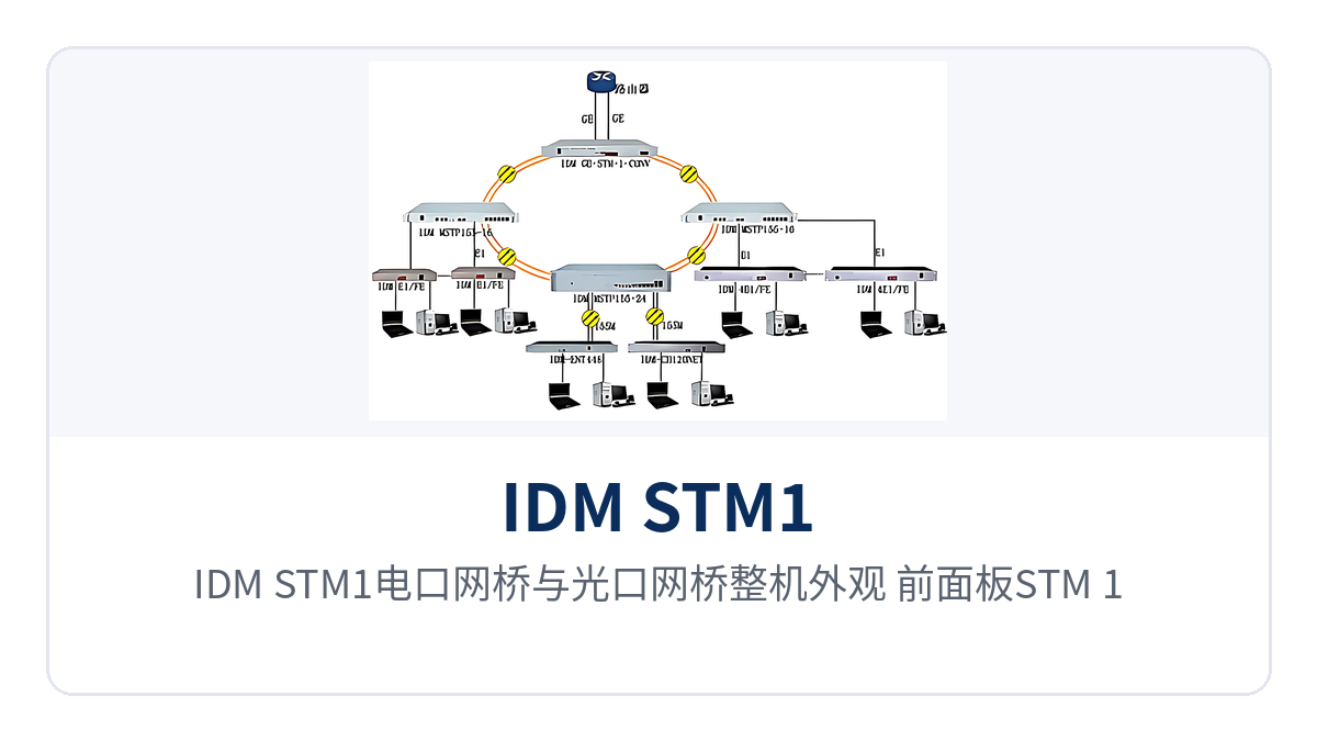
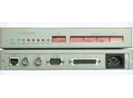
Figure 1: Overall appearance of the IDM STM1 electrical port bridge and optical port bridge — STM-1 interfaces and 4 RJ45 Ethernet ports on the front panel
Key specifications at a glance: 2× STM-1 · 4× Fast Ethernet isolated ports · Gigabit transparent transmission · 63× E1 aggregation · SMC micro-coaxial electrical port · optional dual power supply
What kind of device is an STM-1 Ethernet bridge? How does Ethernet data travel over SDH channels
The line capacity of an STM-1 is divided into channels, and one STM-1 can be split into 63 2M channels. The bridge converter treats these channels as link units and combines any 1 to 63 channels into a single logical link. Ethernet data is carried transparently within the channels, without changing the upper-layer frame format or service configuration.
The number of available channels determines how much bandwidth the Ethernet side can obtain: the more channels allocated, the greater the link bandwidth. Channels on the same device can be assigned separately to different Ethernet ports according to service requirements, and the services do not interfere with one another. This channel-based partitioning lets one device carry multiple leased lines of different sizes at the same time, so small-bandwidth sites do not have to pay for high-capacity configurations.
The 4 100M Ethernet ports are physically isolated from one another inside the device, so traffic from one service does not leak into another, nor do they share the same 100M forwarding capability. For sites that need to terminate terminals by discipline, isolation is already completed on the device side, and subsequent service adjustments no longer require changes to the switch's VLAN plan.
The device supports 1 or 2 STM-1 channels, and the 2-channel configuration can operate in SDH ring networks and chain networks and provide 1+1 protection. Bandwidth is automatically allocated within the channels according to the number of E1 lines, asymmetric E1 line transmission is supported, and single/multi-E1 bridges from different manufacturers are compatible as remote-end devices for hybrid networking.
How to choose among the four models: electrical port bridge, optical port bridge, GE bridge, and optical-to-electrical converter
Selection starts with confirming two things: whether the existing SDH side provides an electrical or optical port, and whether the service side needs Fast Ethernet isolated ports or Gigabit ports. The four models differ mainly in the STM-1 side interface form and the Ethernet side capacity. The table below compares them model by model for easy cross-checking against on-site ports and cable types.
| Model | STM-1 side interface | Ethernet side interface | Application scenario |
|---|---|---|---|
| IDM STM1 electrical port bridge | 1 or 2 STM-1 electrical ports, SMC micro-coaxial connector | 4 physically isolated 100M Ethernet ports, RJ45 | Sites where the SDH equipment already brings electrical ports to the cabinet |
| IDM STM1 optical port bridge | 1 or 2 STM-1 optical ports | 4 physically isolated 100M Ethernet ports, RJ45 | Uplink optical cables already laid, requiring longer-distance access |
| IDM STM1-GE bridge | 2 groups of STM-1 interfaces, optical or electrical | Gigabit Ethernet interface, one optical and one electrical | Aggregation points and leased-line access requiring Gigabit interfaces |
| IDM STM-1 optical-to-electrical converter | 1 group, STM-1 optical-to-electrical conversion, ST/SC optional on the optical port | No Ethernet aggregation | Connecting SDH equipment with only electrical ports to optical cables |
The electrical port bridge and the optical port bridge have identical Ethernet sides; the only difference is whether the STM-1 side is an SMC micro-coaxial electrical port or an optical port. If the existing SDH equipment already brings electrical ports to the cabinet, the electrical port bridge eliminates patch cord adapters; if the uplink is already cabled and long-distance access is required, the optical port bridge is the better choice.
The STM1-GE bridge targets Gigabit services, with 2 groups of STM-1 interfaces, optical or electrical, and a Gigabit Ethernet interface with one optical and one electrical port. 1000M Ethernet is transmitted directly over STM-1 channels with higher bandwidth utilization, making it suitable for aggregation nodes with concentrated services.
The STM-1 optical-to-electrical converter does not perform Ethernet aggregation; it only converts between one group of STM-1 optical and electrical ports. The electrical port is an SMC micro-coaxial connector, the optical port connector is available in ST and SC, and the power supply is available in AC 220V or DC -48V. It is used to connect SDH equipment with only electrical ports to optical cables.
Functions and performance specifications: item-by-item on-site verification
Product capabilities center on four aspects: interface conversion, channel partitioning, isolated bearing, and networking protection. The table below lists each capability and its purpose by function item, for row-by-row reference during selection and goods receipt. Items without values in the table are subject to the accompanying technical documentation and commercial confirmation, and no estimates are made.
| Function | Description |
|---|---|
| 2× STM-1 direct connection to SDH | A single unit provides 1 or 2 STM-1 interfaces and interconnects directly with SDH transmission equipment, with services bypassing intermediate protocol conversion devices. |
| 4× Fast Ethernet isolated ports | Provides 4 physically isolated 100M Ethernet ports with RJ45 interfaces, and the services do not interfere with one another. |
| Gigabit transparent transmission | The STM1-GE bridge provides 1000M Ethernet transmission over STM-1 channels, with one optical and one electrical Gigabit interface. |
| 63× E1 aggregation | Aggregates up to 63 E1 lines into Gigabit Ethernet, with channels 1 to 63 freely partitioned by bandwidth requirement. |
| Transparent channel bearing | Carries Ethernet data with channels as link units, keeping the upper-layer frame format and service configuration unchanged. |
| Ring/chain networking and 1+1 protection | 2× STM-1 can operate in SDH ring networks and chain networks and provide 1+1 protection. |
| Asymmetric bandwidth allocation | Automatically allocates bandwidth within channels according to the number of E1 lines and supports asymmetric E1 line transmission. |
| Hybrid networking | Compatible with single/multi-E1 bridges from different manufacturers as remote-end devices for hybrid networking. |
| Optional dual power supply | Power supply available in AC 220V or DC -48V, 19-inch 1U chassis, with dual power supplies available for critical sites. |
The interface and specification section is grouped by model, STM-1 side, Ethernet side, power supply, and chassis. Nominal values are taken from the original product documentation; on-site verification should follow the port form of the opposite-end device and the accompanying technical documentation. Items without values are noted in the description column with the confirmation method; check each item with the manufacturer before signing the contract.
| Item | Parameter/Specification | Description/Applicable Conditions |
|---|---|---|
| Device model | IDM STM1 electrical port bridge, optical port bridge, STM1-GE bridge, STM-1 optical-to-electrical converter | Four models covering different interface forms and capacities |
| Number of STM-1 interfaces | 1 or 2 (electrical/optical port bridge); 2 groups (GE bridge); 1 group (optical-to-electrical converter) | Determined by model and the number of ports the on-site SDH can provide |
| STM-1 electrical port form | SMC micro-coaxial connector | Direct interconnection with SDH equipment electrical ports, using coaxial patch cords in the cabinet |
| STM-1 optical port form | ST, SC optional (optical-to-electrical converter) | Selected according to the opposite-end optical module and ODF fiber adapter form |
| Ethernet interface | 4 physically isolated 100M Ethernet ports, RJ45 | Configured on the electrical and optical port bridges, used per service port |
| Gigabit Ethernet interface | One optical and one electrical (STM1-GE bridge) | 1000M Ethernet transmitted over STM-1 channels |
| Channel partitioning | Channels 1 to 63 freely partitioned | Allocate the number of channels according to the bandwidth requirement of each service |
| Networking and protection | SDH ring networks, chain networks, 1+1 protection available | Used with the 2× STM-1 configuration |
| Power supply | AC ~220V or DC -48V optional, dual power supply optional | Selected according to the equipment room power supply format |
| Chassis | 19-inch 1U | Standard cabinet installation; can be installed in an integrated cabinet at the site |
| Network management | Unified network management across the network | Network management interface and protocol subject to the accompanying technical documentation |
| Transmission distance and overall power consumption | not yet recorded in the knowledge base | Confirm with the manufacturer according to the optical module grade and power supply configuration |
What 4 physically isolated 100M Ethernet ports mean for a private network
The value of physical isolation is that services share neither bandwidth nor packet forwarding paths. The device provides 4 physically isolated Fast Ethernet ports, so dispatching data, video surveillance, and office services connect to different ports, and abnormal traffic on one port does not squeeze the bandwidth of another.
This isolation approach is consistent with the security zoning requirements of electric power, rail transit, and government private network optical fiber communication solutions: production control services and office services each use their own ports, and the network boundary is already drawn on the device side, making it easier to map boundary descriptions and interface lists item by item during classified protection assessment and security audits. For scenarios such as government private network optical fiber communication solutions and military emergency communications vehicle solutions, the bridge converter can be networked with SDH equipment, MSTP equipment, and optical transmission equipment. As an SDH equipment manufacturer, Raytrans can provide corresponding product showcase and technical support for solution selection and equipment matching.
Partitioning ports by discipline also helps operations and maintenance: when a service is relocated or expanded, only the corresponding Ethernet port is touched, and the cables and configurations of other services remain untouched. During fault location, you can first see which port is reporting an error, then check the corresponding channel on the SDH side.
Typical application scenarios
Electric power private network: substation Ethernet services over existing SDH channels
A batch of 2M channels usually already runs between substations and the dispatching side, and newly added energy metering, records synchronization, and auxiliary control data can use these channels directly. A site installs one electrical port bridge converter, connects directly to the STM-1 electrical port brought out from the SDH equipment, and terminates the 4 isolated 100M ports by service system.
The modification is limited to a coaxial patch cord and 4 network cables inside the cabinet, and the existing SDH time slot planning does not need major changes. The operations side checks device and channel status through network management, and channel alarms can be traced to the specific service port, reducing repeated on-site troubleshooting time.
Rail transit: section sites use optical port bridges to aggregate Fast Ethernet services back to stations
Stations along the line and section equipment rooms are connected by optical cables, and cameras, environmental monitoring, and passenger information terminals all generate Ethernet services. A section site installs one optical port bridge converter, uplinks the STM-1 optical port to the SDH equipment at the station, and terminates different terminals by discipline through the 4 isolated Fast Ethernet ports.
Section equipment rooms have limited space, and the 19-inch 1U chassis with optional dual power supplies can be installed directly in the existing integrated cabinet. The STM-1 side occupies only one pair of optical ports, so no additional protocol conversion device is needed in the section equipment room, reducing both link stages and points of failure and simplifying routine inspection items.
Military and government private networks: STM-1 direct connection and Gigabit transparent transmission for high-capacity leased lines
Aggregation points of military and government private networks often require high-capacity Ethernet leased lines, and the service side wants a Gigabit link straight to the core. The aggregation node uses the STM1-GE bridge to transmit 1000M Ethernet transparently over STM-1 channels, with no protocol converter in between. In military emergency communications vehicle solutions, the device can be deployed on the vehicle and quickly connect to existing SDH equipment to complete service provisioning.
For old SDH equipment with only electrical ports, one STM-1 optical-to-electrical converter converts the electrical port to an optical port for connection to optical cables; when multiple isolated services are needed, an additional electrical or optical port bridge converter can be added, so the same SDH resources can carry multiple private network services at the same time. This also applies to aggregation node construction in government private network optical fiber communication solutions.
What to check during on-site deployment and commissioning
Deployment follows four steps: interface verification, channel planning, alignment at both ends, and commissioning verification. The key is to clearly match the STM-1 interface form, the number of channels, and the Ethernet port allocation to avoid rework and rewiring after commissioning. The items below can be checked off one by one during the construction briefing.
- Confirm the interface form first: determine whether the existing SDH side uses an SMC micro-coaxial electrical port or an optical port, and select an electrical port bridge converter, an optical port bridge converter, or an optical-to-electrical converter accordingly.
- Determine the number of channels by bandwidth: estimate the bandwidth required by each service, convert it into 1 to 63 channels, and keep the channel assignment consistent at both ends.
- Plan Ethernet ports by service: assign the 4 isolated 100M ports to specific service systems in advance and record them in the handover sheet to avoid on-site rewiring.
- Check the power supply format: determine whether the equipment room provides AC 220V or DC -48V, and select the option according to on-site conditions; add dual power supplies at critical sites.
- Match the optical port connectors: the optical ports of the optical-to-electrical converter are available in ST and SC types, and the patch cords must match the fiber adapters on the optical distribution frame.
- Verify port by port during commissioning: test the connectivity and available bandwidth of each Ethernet port one by one, and confirm that there are no persistent alarms on the STM-1 side.
- Connect network management in advance: plan the network management channel, and confirm that the device can be incorporated into the unified network management system before handing it over to operations and maintenance.