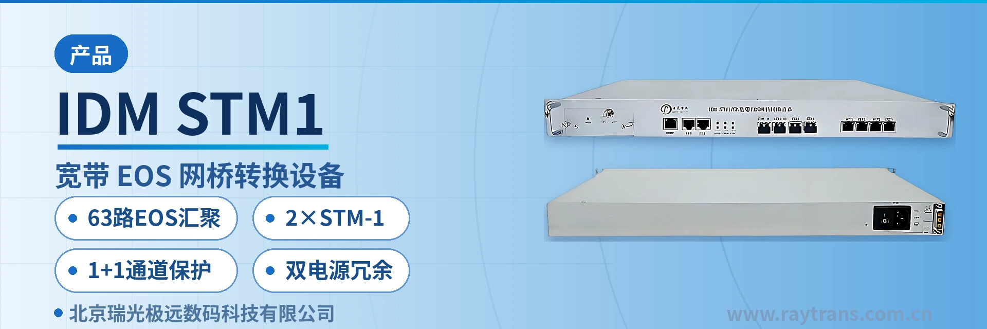
IDM STM1/GE Central Office EOS Network Bridge
63-channel EOS standalone aggregation saves 63 2M conversion devices dual STM-1 1
The basic function of the IDM STM-1/GE is to demultiplex the Ethernet frames arriving at the GE port into different flows (using the MAC address, VLAN TAG and other information carried in the Ethernet frames themselves), then encapsulate the Ethernet frames of different flows into GFP frames (forming an EoS signal), and then map the GFP frames into different VCGs (each VCG can contain 1 to 63 VC12 channels);
IDM STM-1/GE 63-Channel EOS Aggregation Network Bridge is an aggregation-type EOS device supporting GFP encapsulation, developed by Beijing Ruiguang Jiyuan Digital Technology Co., Ltd. (Raytrans). As a professional bridge converter, it maps Ethernet services in GE ports into SDH VC12 channels and aggregates EOS signals from multiple remote sites at the central office. The device is typically deployed at the central office and works with remote EOS devices in a networking setup, delivering Ethernet data to remote stations over the existing TDM network. It is suitable for scenarios such as government private network optical fiber communication solutions and military emergency communications vehicle solutions.
A single device can aggregate 63 EOS signals into GE/FE ports, so a central equipment room no longer needs a separate converter for each 2M-level service. Ethernet frames from remote stations are re-merged here by VLAN and port, then uplinked to SDH transmission equipment through one gigabit port, reducing rack positions, patch cords and points of failure accordingly. As an SDH equipment manufacturer, Raytrans highlights in its product showcase the device's synergy with SDH equipment and optical transmission equipment, and its MSTP features complement media converter manufacturer solutions.
The unit uses a standard 19-inch 1U chassis with dual power supply redundancy. The front panel provides link and service status indication, and the console port is used for local configuration and on-site troubleshooting. The device offers both console and SNMP network management interfaces, and the software supports online upgrade, so equipment room renovation and subsequent maintenance require no disassembly.
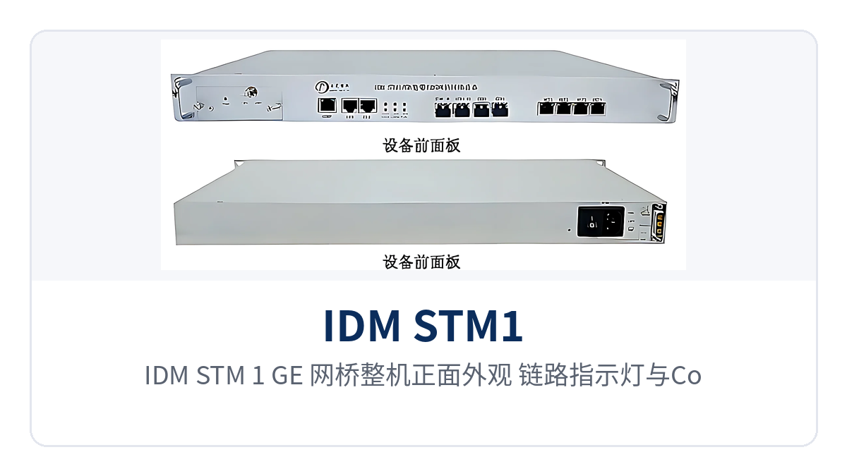
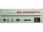
Figure 1: Front appearance, link indicator LEDs and console configuration port of the IDM STM-1/GE network bridge
Key Specifications at a Glance: 2×STM-1 · 63-channel EOS aggregation · 1 optical + 1 electrical GE + 2 FE · VCAT/LCAS/GFP · dual power supply redundancy · overall power consumption <30W
What Kind of Device Is the IDM STM-1/GE 63-Channel EOS Aggregation Network Bridge?
The processing chain has three steps: first, traffic in the GE port is split by the MAC address and VLAN TAG carried in the Ethernet frames; then the Ethernet frames of different flows are encapsulated into GFP frames to form EoS signals; finally, the GFP frames are mapped into different VCGs according to site bandwidth requirements. Each VCG can contain 1 to 63 VC12s, split flexibly as services require.
The reverse direction is processed in the opposite order: VC12s in the STM-1 signal are demapped first, then Ethernet data is restored by VCG and aggregated to the GE port, where flows from different VCGs are marked differently at the GE egress, for example with different VLAN TAGs. The entire conversion is transparent to the upper-layer network, and the two ends can intercommunicate once configured with the same encapsulation profile. As a bridge converter designed for central office aggregation, the device plays the role of Ethernet service adaptation and aggregation within SDH equipment and optical transmission equipment systems. It can be networked with SDH equipment manufacturer products of the Raytrans series, and is often paired with media converter manufacturer remote devices to form access aggregation nodes in a complete government private network optical fiber communication solution or military emergency communications vehicle solution.
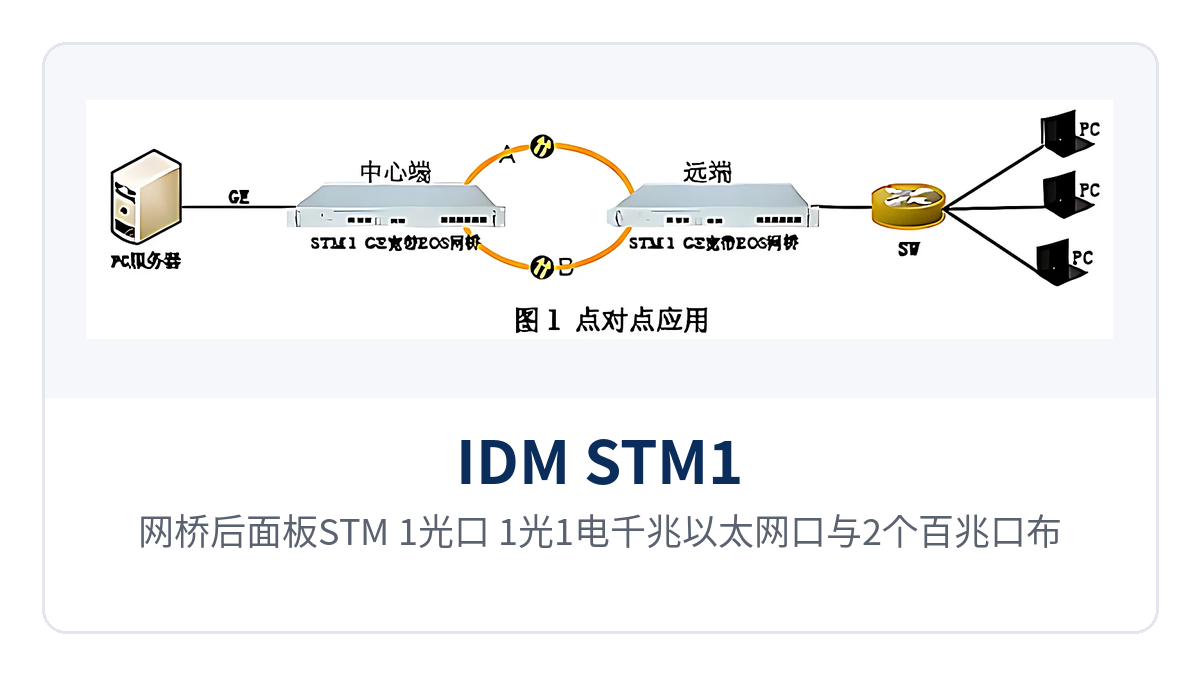
Figure 2: Rear panel layout of the network bridge with STM-1 optical ports, 1 optical + 1 electrical gigabit Ethernet ports and 2 Fast Ethernet ports
What Functions Does This Device Offer? Item-by-Item Comparison with On-Site Requirements
The functions focus on four aspects: frame splitting and encapsulation, channelized transport, Ethernet switching, and management and protection, each corresponding to an action verifiable on site. The table below lists capabilities and effects by function item, so that during selection you can compare them row by row against the number of channels, Ethernet interface form and O&M approach at your site.
| Function | Description |
|---|---|
| Ethernet frame splitting and EOS encapsulation | Splits traffic in the GE port by MAC address and VLAN TAG, encapsulates each flow into GFP frames, and sends the resulting EoS signals into SDH channels for transport. |
| 63-channel EOS aggregation | A single STM-1 can map 63 VC12s; together with multiple VCGs, it aggregates EoS signals from multiple sites into GE/FE ports, which is the core capability of central office aggregation. |
| 2 STM-1 interfaces | Operate in SDH ring networks and chain networks, support 1+1 lower-order path protection mode, and the 2 optical ports can correspond to two transmission directions respectively. |
| Gigabit and Fast Ethernet ports | 1 optical + 1 electrical gigabit ports plus 2 Fast Ethernet ports, full-duplex/half-duplex, adaptive, flow control, MDI/MDIX. |
| VCAT virtual concatenation | Complies with ITU-T G.7043; Ethernet frames are carried to VCGs by byte interleaving, and bandwidth stacks up according to the number of VC12s. |
| LCAS link capacity adjustment | Complies with ITU-T G.7042, supports automatic identification of VC12 link sequence, and supports automatic VC12 link setup and teardown. |
| GFP encapsulation | Complies with ITU-T G.7041 and G.8040, and supports FCS configuration of GFP frames. |
| VLAN-based aggregation | Aggregates remote device data into the corresponding GE/FE ports by VLAN ID; remote packets must carry TAGs and the VLAN IDs of different remote sites must not duplicate. |
| Ethernet switching management | Supports link aggregation, port mirroring, ingress/egress bandwidth limiting, MAC address table management (depth 8K), storm suppression and QOS on panel switching ports; frame length supports 2048 bytes. |
| SDH clock | Supports master clock and slave clock modes; in slave clock mode, supports automatic clock source switchover. |
| Automatic laser shutdown | Both STM-1 ports and GE ports support the ALS function, automatically shutting down the laser when there is no signal on the optical port. |
| Fault diagnosis | Provides VCG loopback detection and switching port loopback detection for segment-by-segment link fault location. |
| In-band management | Supports in-band management based on GFP frames and a network management channel based on the management VLAN; both methods can manage remote devices. |
| Network management and upgrade | Provides console and SNMP network management interfaces, with online software upgrade; network management functions cover configuration, topology, resource, alarm, performance, maintenance, system and security management. |
| Dual power supply redundancy | 19-inch 1U chassis, dual power supply redundancy design, overall power consumption <30W. |
Technical Specifications and Interface Specifications
Parameters are grouped by interface, standard, switching capability and unit configuration, and nominal values follow the product documentation. For on-site verification, refer to the interface form of the opposite-end SDH equipment and the accompanying technical documentation; confirm optical module models and power supply formats with the manufacturer according to equipment room conditions.
| Item | Parameter/Specification | Description/Applicable Conditions |
|---|---|---|
| Device model | IDM STM-1/GE broadband EOS network bridge converter | Central office aggregation-type device, networked with remote EOS devices |
| Number of STM-1 interfaces | 2 | Supports ring network and chain network networking and 1+1 lower-order path protection |
| Channel capacity per interface | 63 VC12s (63 EOS channels) | Each VCG can contain 1 to 63 VC12s, split by site bandwidth |
| Gigabit Ethernet interface | 1 optical + 1 electrical, 2 in total | Full-duplex/half-duplex, adaptive, flow control, MDI/MDIX |
| Fast Ethernet interface | 2 | Panel switching ports like the gigabit ports, can be used for link aggregation |
| Encapsulation and concatenation standards | GFP complies with G.7041 and G.8040, VCAT with G.7043, LCAS with G.7042 | Both ends configured with the same standard and encapsulation profile |
| Switching capability | MAC address table depth 8K | Supports port mirroring, ingress/egress bandwidth limiting, storm suppression and QOS |
| Frame length | Supports 2048 bytes | Upper limit of Ethernet frame length; verify jumbo frames against on-site service requirements |
| Clock mode | Master clock mode and slave clock mode | Automatic clock source switchover in slave clock mode |
| Management interface | Console interface, SNMP network management interface | Software supports online upgrade |
| In-band management | GFP frame in-band management, management VLAN network management channel | Both in-band methods can deliver configurations to and query status of remote devices |
| Chassis and power supply | Standard 19-inch 1U chassis, dual power supply redundancy | Rack-mounted installation, dual power feeds connected simultaneously |
| Overall power consumption | <30W | Power consumption profile for long-term operation in equipment rooms and unattended sites |
Four Capability Tags: 63-Channel EOS Aggregation, Dual STM-1 Ports, 1+1 Path Protection, Dual Power Supply Redundancy
In on-site discussions, four phrases are often used to summarize the device's capabilities. Purchase, design and operation and maintenance contacts can remember these four terms first; the table below explains the boundary conditions and implementation of each. The four phrases correspond to the four dimensions of capacity, transmission direction, protection and power supply, and the same set of wording can be used in quotations, system diagrams and acceptance documents.
| Differentiation Point | Value on Site |
|---|---|
| 63-channel EOS aggregation | A single device aggregates 63 EOS signals into GE/FE ports, so the central office collects 2M-level services from multiple sites with one unit and no longer stacks converters in the equipment room. |
| Dual STM-1 ports | The 2 STM-1 optical ports can correspond to two directions respectively, interfacing with two remote network bridge devices and providing GE and FE service access respectively. |
| 1+1 path protection | The STM-1 side works in 1+1 lower-order path protection mode; when the active channel fails, services switch over to the backup channel, so the private network link is not interrupted. |
| Dual power supply redundancy | 19-inch 1U chassis with redundant power supply, overall power consumption <30W, suitable for long-term operation in equipment rooms and unattended sites. |
All four tags can be found in corresponding rows of the function table and parameter table, and can be quoted directly in purchase lists. Note the distinction: path protection acts on the STM-1 transmission side, while dual power supply redundancy acts on the device power supply side; the two mechanisms do not replace each other, and should be verified separately during design according to the site's reliability requirements. In the product showcase for government private network optical fiber communication solutions and military emergency communications vehicle solutions, the above four tags are often the key points Raytrans uses to introduce the network bridge converter's capability of coordinate networking with MSTP/SDH equipment.
How to Deploy: Point-to-Point, Multi-Direction Tree and Ring Network
As an SDH network bridge converter, the device can be networked in three ways: point-to-point, multi-direction tree and ring network. The service interfaces on the site side and the channel planning on the central side are determined together during configuration. The applicable conditions of each mode are described below. All three modes share the same device and channel planning method; the differences lie in the number of STM-1 optical ports used and the protection configuration.
- Point-to-point: two devices are interconnected through an STM-1 optical direction to achieve point-to-point intercommunication of GE and FE at both ends, suitable for an independent dedicated line between two equipment rooms.
- Multi-direction tree: the device's 2 STM-1 optical ports correspond to two directions respectively, interfacing with 2 remote network bridge devices and providing GE and FE service access respectively.
- Ring network: the device is deployed in a key account central equipment room or carrier equipment room, with same-series devices at branch nodes for access; the STM-1 side can work in 1+1 lower-order path protection.
- Working with media converters: the device provides GE optical ports and can connect directly to media converters for gigabit Ethernet service access in remote areas, also facilitating matching selection by media converter manufacturers.
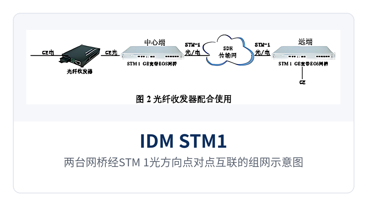
Figure 3: Networking diagram of two network bridges interconnected point-to-point through an STM-1 optical direction
In point-to-point mode, the parameters of the devices at both ends are configured symmetrically; the service side sees standard Ethernet interfaces, and the intermediate link is carried at the SDH layer. The receive/transmit optical power and channel numbers of the optical ports at both ends of the link must be configured in one go, and both ends must be updated in sync after any change at either end, avoiding the situation where traffic passes in one direction but not the other.
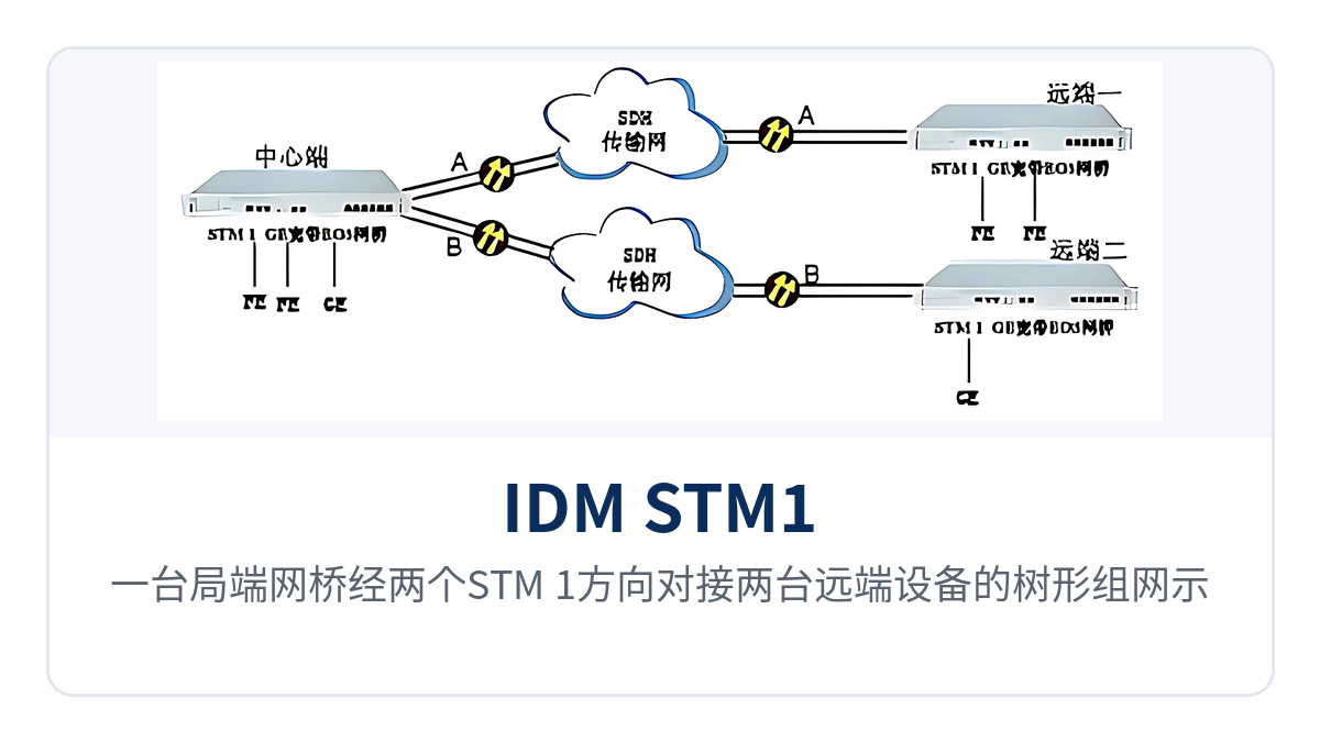
Figure 4: Tree networking diagram of one central office network bridge interfacing with two remote devices through two STM-1 directions
The multi-direction tree topology addresses the problem of supplying services from the central equipment room to branches on both sides simultaneously. The two STM-1 directions each form an independent chain, so optical path inspection in one direction does not affect services in the other. When service volumes differ greatly among branches, VC12 channels can be allocated according to the actual demand of each direction.
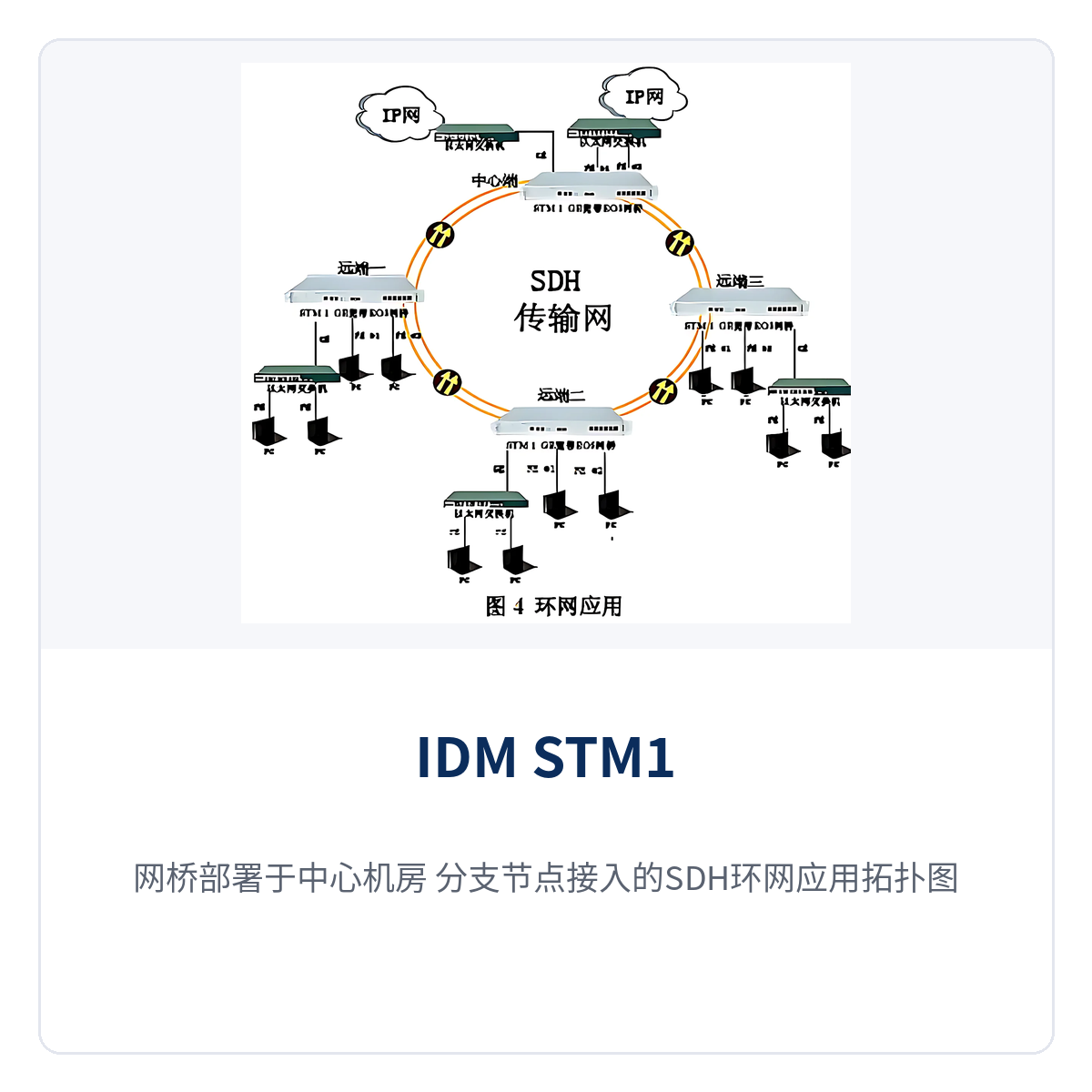
Figure 5: SDH ring network application topology with bridges deployed in the central equipment room and branches connected at branch nodes
In ring network mode, VLAN IDs across the entire private network must be planned uniformly. Port VLANs work together with 802.1Q VLANs to isolate different branches and even different types of services. Branch nodes are equipped with devices of the same series to provide access, delivering data services with bandwidth from 2M to N×2M for each branch user.
Typical Application Scenarios
Electric Power and Energy Private Network: Central Office Aggregates 2M-Level Services from Multiple Sites
Between substations, power supply stations, and the dispatch center, a batch of 2M channels usually already carries production services, and newly added Ethernet data can be transmitted directly over these channels. A 63-channel EOS aggregation bridge is installed in the equipment room on the dispatch side, where EOS signals from all sites are aggregated into GE ports and then uplinked to SDH equipment.
Sites only need the corresponding EOS access devices. The service side sees standard Ethernet interfaces, and the existing network structure does not need to be changed. The upgrade effort is concentrated on rack positions, patch cords, and VLAN planning on the equipment room side. Dual power supply redundancy and overall power consumption below 30 W also suit the operating conditions of unattended sites.
Rail Transit Communication: Bandwidth Divided by Channel at Stations Along the Line
Service volumes vary greatly between stations along the line and section equipment rooms. Some sites need only one VC12, while others need to bundle multiple channels. The equipment divides bandwidth by VCG on the central side, and different stations are allocated VC12 channels according to actual service volume. Ethernet terminals such as cameras and environmental monitoring devices connect to existing SDH channels.
LCAS allows the number of channels to be adjusted with services: when a link is added, the equipment automatically establishes it; when a link is removed, the equipment automatically tears it down. The wiring sequence of VC12 links is also identified automatically, so O&M personnel do not need to configure them one by one manually. Section sites do not require dedicated staff on duty, and alarms can be located to a specific channel on the central network management system.
Military and Government Private Networks: Existing SDH Circuits Carry New Ethernet Services
Between equipment rooms of military and government private networks, often only SDH circuits are allocated, and new Ethernet services need to be accessed without changing the existing transmission configuration. IDM STM-1/GE accesses in line with the standard GFP, VCAT, and LCAS specifications, and provides GE and FE ports on the service side. The upgrade effort is concentrated on one 1U device and two patch cords, while the original frame structure and service configuration of the private network remain unchanged.
Private network links span regions with long hop distances, making fault location costly. VCG loopback detection and switching port loopback detection isolate faults to a specific segment. Console local configuration plus SNMP remote monitoring, together with GFP frame-based in-band management and a management VLAN network management channel, allow sites without a dedicated management channel to check operating status remotely.