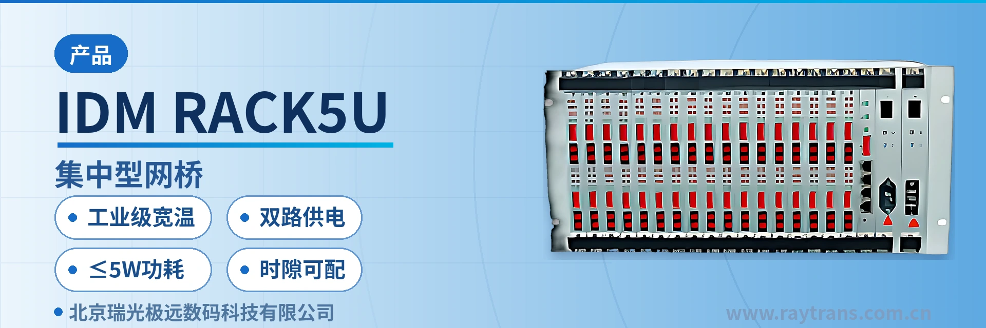
IDM-RACK5U Centralized Bridge
5U front-card mixed insertion saves rack positions; one card supports two remote ends, up to 32 channels at full configuration; card replacement without removing the unit
The IDM-RACK5U centralized bridge is a rack-mounted, small-capacity multi-user access network platform system designed for star network topologies with large-user access. It offers high integration and strong compatibility, and can be flexibly configured with different quantities and types of
IDM-RACK5U centralized bridge is a 5U front-loading card centralized bridge developed by Beijing Ruiguang Jiyuan Digital Technology Co., Ltd. It is used to aggregate a large number of remote Ethernet access connections at the central node of a star network topology, and is a product showcase solution for multi-site access scenarios. The unit adopts a 19-inch 5U front-loading card structure; bridge cards and optical modem boards can be mixed in the same chassis, each service card corresponds to two remote single-E1 bridges (optical modems), and a fully configured chassis can connect 32 remote sites.
As a centralized bridge converter device, it solves the problem of equipment stacking in the central equipment room in large-user access. In the past, a point-to-point bridge was placed at each end of an E1 link; as sites increased, the equipment room filled with rows of standalone small boxes and bundles of patch cords. With a multi-slot chassis at the central side, multiple remote directions are consolidated into one 5U device, and rack positions, power supply and network management entry points are reduced accordingly. On this model, Raytrans continues the design approach of sharing a common platform between PCM equipment and bridge converters, and service cards and optical modem boards can be flexibly mixed.
Key Specifications at a Glance: 5U front-loading card · 16 service cards mixed insertion · two remote sites per card · 32 remote sites at full configuration · configurable E1 time slots · industrial grade -40℃~+85℃ · AC220V/DC-48V dual power supply · overall power consumption ≤5W
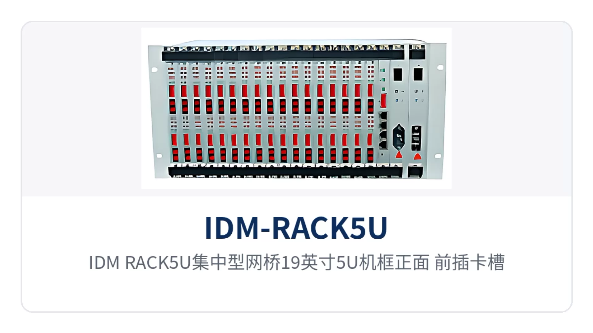
Figure 1: Front view of the 19-inch 5U chassis of the IDM-RACK5U centralized bridge, close-up of front-loading card slots and power/alarm indicators
What kind of device is the 5U front-loading card centralized bridge?
The 5U front-loading card centralized bridge turns the central side of a star network into a multi-slot chassis; service cards are inserted from the front of the chassis, and one card carries two remote devices in one direction. The remote site only needs one desktop single-E1 bridge; services return to the equipment room over existing E1 or optical fiber resources and are terminated uniformly in the chassis, so the central equipment room does not need to stack standalone devices according to the number of remote sites. As a representative device of Raytrans's centralized product line, this chassis is often presented alongside various bridge converters and PCM equipment in the product showcase, making it easy for users to select uniformly in a government private network optical fiber communication solution.
Maintenance actions for the front-loading card structure are concentrated on the front of the chassis. When a single card fails, it is pulled out and replaced, while services on other cards in the same chassis continue to run, with no need to remove the whole unit or re-lay central-side patch cords. The device panel provides operating indicators and line alarm indications, so on-duty personnel standing in front of the cabinet can determine whether a failure lies at the central side, the line side or the remote side.
The IDM-RACK5U centralized bridge is positioned as a small-capacity multi-user access platform: high integration and strong compatibility, with fewer service cards configured according to the initial project scale and more cards added for capacity expansion as sites grow. This configuration approach aligns initial investment with the pace of service provisioning and keeps the variety of spare parts concentrated during later upgrades and maintenance. For integrators looking for an optical multiplexer manufacturer, this type of chassis-based bridge converter and PCM equipment can be included in the same supply system, reducing compatibility risks caused by piecing together multiple manufacturers.
How many remote devices can one chassis connect?
With 16 service cards at full configuration, one chassis can connect 32 remote sites, because each service card corresponds to two remote single-E1 bridges (optical modems). The remote side is a desktop single-E1 bridge providing 4 shared Ethernet interfaces; each service card at the central side provides 2 physically isolated Ethernet interfaces, and the two service channels on the same card do not interfere with each other.
Slot planning is based on 19 slots, including 2 power card slots, 16 service card slots and 1 network management card slot; the network management card slot can also be changed to a service expansion card. The following table shows the correspondence between chassis slots and service cards; when preparing a configuration list, check each item according to the actual number of remote sites.
| Card slot type | Quantity | Description |
|---|---|---|
| Power card | 2 | AC220V and DC-48V formats optional, overall power consumption ≤5W |
| Service card | 16 | Each card corresponds to 2 remote single-E1 bridges, connecting 32 remote sites at full configuration |
| Network management card | 1 | Can also hold a service expansion card, selected according to the expansion needs of the site |
| Total slots | 19 | 19-inch 5U chassis, front-loading card type, service cards can be replaced online |
Service cards are selected according to the remote type, and bridge cards and optical modem boards can be mixed in the same chassis. Whichever type of desktop device is already deployed at the remote site, the corresponding card type is configured at the central side, without changing the existing remote configuration or requiring all site service types in the same chassis to be identical. In the practice of government private network optical fiber communication solutions, Raytrans often uses this mixed insertion approach to interface with existing bridge converters and PCM equipment, protecting the user's earlier investment.
What functions does the centralized bridge provide?
The chassis functions are organized around centralized termination, transparent Ethernet transmission and centralized management; service capabilities are determined by the installed service cards, while common capabilities are provided uniformly by the chassis. The following table lists each capability and its role by function item; during selection, compare row by row against the number of remote sites at the site, the E1 time slot arrangement of the link and the O&M approach.
| Function | Description |
|---|---|
| 5U front-loading card structure | 19-inch 5U chassis, 2 power cards, 16 service cards, 1 network management card; service cards are plugged in and out from the front |
| Two remote sites per card | Each service card corresponds to two remote single-E1 bridges (optical modems), connecting 32 remote sites at full configuration |
| Physically isolated Ethernet ports | Each card at the central side provides 2 physically isolated Ethernet interfaces, and the two service channels do not interfere with each other |
| E1 local and remote loopback | Supports E1 local loopback and remote loopback to determine by segment whether a failure lies at the central side, the line side or the remote side |
| Framed and unframed configurable | Supports framed and unframed modes; framed mode supports PCM30/31 and CRC-4 adaptive |
| Configurable time slots | In framed mode, time slots are arranged according to the actual occupation of private network services, without giving the entire E1 to one service |
| VLAN jumbo frame transparent transmission | Transparent transmission of jumbo frames specified by IEEE 802.1Q, allowing direct connection to Ethernet switches with VLAN functions |
| Ethernet loopback protection | Prevents Ethernet data loopback, avoiding network-wide broadcast storms caused by line self-loop |
| Data frame filtering and flow control | Local data frame filtering, PAUSE flow control and MDI/MDIX auto-sensing |
| Dual network management channels | Serial port (RS485) network management and Ethernet network management, configuring operating parameters and monitoring operating status |
| Clock and alarm | Supports master timing and tracking timing, with complete line alarm indications for judging whether the timing source is normal |
The common capabilities in the table above are provided jointly by the chassis and the network management card, while service cards are selected as needed. It should be noted that E1 time slot configuration is a parameter that must be aligned between the service card and the remote bridge, whereas the Ethernet rate and duplex mode are generally set to adaptive when connecting to a switch; the two types of configuration are performed in different places. As an optical multiplexer manufacturer, Raytrans fully discloses the above function items in the product showcase, making it convenient for users to include this chassis, bridge converters and PCM equipment uniformly in network management and spare parts planning in a government private network optical fiber communication solution.
Key Specifications and Interface Specifications
The four groups of parameters—optical interface, E1 interface, Ethernet interface and power supply environment—are as follows; take values from the table when checking the configuration list and equipment room conditions. The nominal values in the table follow the product documentation; on site, the interface form of the opposite-end transmission device and the accompanying technical documentation prevail, and the optical module model and power supply format are confirmed according to site conditions.
| Item | Parameter/Specification | Description/Applicable Conditions |
|---|---|---|
| Interface type | FC (SC and others can be customized) | Selected according to the on-site optical distribution frame and patch cord interface |
| Mode/distance | Single-mode (multi-mode optional) / distance optional | Single-mode for longer distances, multi-mode for short-distance interconnection within the equipment room |
| Optical fiber rate | 155bps±50ppm | Corresponds to 155M optical interface capability; factory nominal values follow the product documentation |
| Wavelength | 1310nm | Conventional transmission window of single-mode fiber |
| Transmit optical power | -2~-11dBm | Transmit optical power range, used to calculate the optical power budget of the link |
| Receiver sensitivity | Better than -36dBm | Lower limit for normal data reception at the receiving end, with margin remaining on weak optical links |
The E1 interface is designed according to ITU-T G.703, with 75Ω and 120Ω impedance options and configurable framed and unframed modes. The following table lists the key parameters of the E1 side; check each item before interfacing with the 2M interface of the opposite-end transmission device or existing PCM equipment.
| Item | Parameter/Specification | Description/Applicable Conditions |
|---|---|---|
| Bit rate | 2048Kbps±50ppm | Nominal rate of a single E1, consistent with the transmission-side clock |
| Line coding | HDB3 | Interfacing with the 2M interface of existing PCM equipment and SDH transmission equipment |
| Standard protocol | Supports ITU-T G.703 | Basis for the physical layer and electrical characteristics of the E1 interface |
| Impedance | 75Ω/120Ω | Unbalanced coaxial and balanced twisted pair cable forms optional |
| Frame structure | PCM30/31 | Frame structure in framed mode; configurations at both ends must be consistent |
| Signaling | Channel-associated signaling (CAS) | Consistent with the signaling configuration of the opposite-end device |
| Jitter characteristics | ITU-T G.823 | Basis for jitter tolerance of clock recovery after multi-stage transmission |
| Mode | Configurable (un)framed, configurable time slots | Time slots arranged according to the actual occupation of private network services |
The Ethernet side is an RJ-45 electrical interface, with a configurable rate of 10M/100M and configurable full-duplex or half-duplex operating mode; performance is tested according to RFC2544. Ethernet frame length supports 64~1516byte, and jumbo frames specified by IEEE 802.1Q can be transparently transmitted, so there is no need to rewrite tags when connecting to switches with VLAN functions.
| Item | Parameter/Specification | Description/Applicable Conditions |
|---|---|---|
| Interface type | RJ-45 | Standard Ethernet electrical interface, supports MDI/MDIX |
| Transmission rate | Configurable 10M/100M | Rate matched to the on-site switch and service volume |
| Standard protocol | Supports IEEE802.3 | Interoperates with conventional Ethernet devices |
| Operating mode | Configurable full/half duplex | Usually set to adaptive when connecting to a switch |
| Frame length | 64~1516byte | Jumbo frames transparently transmitted per IEEE 802.1Q |
| Performance standard | RFC2544 | Test basis for throughput, packet loss and latency |
| Packet loss rate | <0.01% | Packet loss level under normal forwarding |
| Latency | ≤100μs | Forwarding latency of a single device, excluding line transmission latency |
The parameters of power supply and operating environment are as follows; check each item before selecting the cabinet position, connecting power and configuring field sites. Overall power consumption is ≤5W, so power supply and heat dissipation margins are relatively ample when multiple devices are installed side by side in the same cabinet; the industrial-grade wide temperature configuration covers -40℃+85℃, with relative humidity 095% (non-condensing).
| Item | Parameter/Specification | Description/Applicable Conditions |
|---|---|---|
| Power supply mode | AC220V/DC-48V | Dual power supply formats, selected according to equipment room or site power conditions |
| Overall power consumption | ≤5W | Low power consumption, low pressure on cabinet power supply and heat dissipation |
| Operating temperature | -15℃~+65℃ | Standard-temperature model, for attended equipment rooms |
| Storage temperature | -25℃~+75℃ | Transportation and storage conditions |
| Industrial grade | -40℃~+85℃ | Wide-temperature configuration, for field racks and unattended sites |
| Relative humidity | 0~95% (non-condensing) | Condensation environments must be avoided; keep the cabinet ventilated |
Four Capability Labels: Industrial-Grade Wide Temperature, Dual Power Supply, ≤5W Power Consumption, Configurable Time Slots
In on-site discussions, the capabilities of this device are often summarized into four short labels; purchase, design and operation and maintenance contacts can remember these four words first. The four labels correspond to the four dimensions of environmental adaptability, power conditions, operating cost and service adaptation; the boundaries and implementation of each are explained below.
- Industrial-grade wide temperature: The wide-temperature configuration covers -40℃ to +85℃, with relative humidity of 0–95% non-condensing. Field racks and equipment rooms without air conditioning can be selected according to these conditions.
- Dual power supply: AC220V and DC-48V formats are available. Communications equipment rooms take DC, while stations and office equipment rooms take AC. The same platform is delivered according to site conditions.
- ≤5W power consumption: Overall power consumption is ≤5W. When multiple devices are installed in the same cabinet, the requirements for power supply capacity and heat dissipation are low, and long-term operation incurs low electricity costs.
- Configurable time slots: In E1 framed mode, time slots are configured according to service occupancy. With 75Ω/120Ω impedance options, the time slot arrangement of existing 2M channels in private networks can be accommodated.
All four labels can be found in the parameter table, and the procurement list can reference them directly. Note that the wide-temperature capability depends on the model configuration at the time of ordering; standard-temperature models and industrial-grade models have different temperature ranges. E1 time slot configuration must be consistent at both ends; if one end is changed, the other end must be changed accordingly.
How Is Star Networking Deployed?
The deployment sequence for star networking is to first determine the central slot, then determine the remote card type, and finally verify optical power and power supply. A centralized IDM-RACK5U bridge is installed in the central equipment room, and a desktop single-E1 bridge (optical modem) is installed at each remote station. One E1 circuit or one optical fiber corresponds to one remote direction, and services are aggregated at the central side. As a mature product showcase from an optical multiplexer manufacturer, this combination is commonly used in government private network optical fiber communication solutions for multi-site distributed access scenarios, with centralized aggregation at the central side and lightweight deployment at the remote side.
Proceed on site in the following order. Completing selection, power supply verification, and optical power calculation before commissioning can reduce rework. If the list is incompletely registered or the power budget is missed, problems often only surface when services are connected, at which point the cost of changes is significantly higher.
- Compile a list of remote stations, register the service type and link form (E1 circuit or optical fiber) station by station, and determine the remote bridge model and central-side card type accordingly;
- Determine the number of service cards according to the number of remote ends. Each card supports two remote ends. Reserve spare slots for later capacity expansion. Network management card slots can be changed to service cards as required;
- Verify the power supply conditions of the central equipment room, select the AC220V or DC-48V format, and confirm the power supply branch capacity and grounding method corresponding to overall power consumption ≤5W;
- Calculate the optical power budget according to the optical cable length and number of connectors for each section, and confirm that the optical power at the receiving end is above the -36dBm sensitivity lower limit;
- Commission card by card. First use E1 local loopback and remote loopback for segmented verification. After confirming that the central side, line side, and remote side are all normal, connect services.
Remote station devices are small and flexible in installation position. Service-side interfaces are connected once at the remote end, and only one card is added to the chassis at the central side. When expanding a station, the center does not add cabinets or rearrange patch cords; simply add cards in the remaining slots. This is especially convenient in private network projects with distributed sites and year-by-year additions. The bridge converters and PCM equipment provided by Raytrans work together on the same platform. The bridge converter at the central side handles aggregation, and the PCM equipment at the remote end handles service access. This overall solution has many deployed cases in government private network optical fiber communication solutions.
Typical Application Scenarios
Electric Power Private Network: Centralized Access for Substations and Power Supply Stations
Sites in electric power private networks are distributed across substations, power supply stations, and switching stations. These stations carry not only Ethernet data from protection and measurement and control devices, but also auxiliary monitoring and video services. A desktop single-E1 bridge is installed at each remote station, and services return to the power supply company equipment room along existing E1 circuits. At the equipment room side, a single 5U chassis provides unified aggregation, so multiple power supply stations do not each need a standalone device. In this type of product showcase, Raytrans, as an optical multiplexer manufacturer, has long provided bridge converters and PCM equipment to the electric power industry, and its government private network optical fiber communication solutions have mature deployments in electric power private network scenarios.
Electric power communications equipment rooms are mostly powered by -48V DC. The chassis supports DC-48V input and connects to the existing DC distribution panel in the equipment room. Overall power consumption is ≤5W, so when multiple devices are installed in the same cabinet, the pressure on power supply capacity and heat dissipation is low. Upgrade projects do not need to recalculate the equipment room load for newly added devices.
Rail Transit Communication: Access Aggregation for Trackside Equipment Rooms and Stations Along the Line
Rail transit communication nodes are distributed along the line, with long distances and many nodes among stations, trackside equipment rooms, and the control center. At the central side, one 5U chassis aggregates the Ethernet services sent from stations along the line. Each station selects card types according to service volume, and stations do not interfere with one another. A failure at a single station affects only the corresponding card.
Most trackside equipment rooms are unattended, and the temperature inside the cabinet fluctuates greatly with the seasons. The industrial-grade wide-temperature configuration supports operation from -40℃ to +85℃ and relative humidity of 0–95% non-condensing, making it suitable for such equipment room conditions. E1 time slots are configurable, and section services are assigned time slots according to actual occupancy, so it is not necessary to allocate an entire 2M channel to one service.
Unattended Field Sites: Rack-Mountable with a Single DC Power Feed
Unattended field sites usually have only a single DC power feed, and the equipment room has no air conditioning or dehumidification. The device supports DC-48V power supply with overall power consumption ≤5W. When multiple devices are installed in the cabinet, the requirements for solar power or storage battery capacity are low, making site expansion easier to implement.
Field racks experience large temperature differences and humidity changes. The wide-temperature configuration covers -40℃ to +85℃ and humidity of 0–95% non-condensing, so long-term operation does not depend on equipment room environmental control. The device provides serial port (RS485) network management and Ethernet network management. On-duty personnel can read the operating status of each card from the center, reducing the number of maintenance trips to the field.
Selection and Deployment Recommendations
Selection is determined item by item according to four factors: number of remote stations, link form, E1 time slot arrangement, and environmental power supply conditions. This determines the complete configuration. As the centralized model in the bridge converter category, slot allocation corresponds one-to-one with the remote list, and the configuration table can be used directly as the basis for procurement and construction. The PCM equipment and bridge converters provided by Raytrans can be mixed in the same chassis. Combined with the overall design of the government private network optical fiber communication solution, this covers the complete link from the central equipment room to remote stations.
- The number of sites determines the number of service cards. One card supports two remote ends. Configure cards according to the current number of sites plus a certain margin, with the margin reserved as empty slots;
- The link form determines the remote device and central card type. E1 circuits use single-E1 bridge cards, and direct fiber connections use optical modem cards. Mixed insertion in the same chassis does not affect each other's services;
- The E1 time slot arrangement determines the framing mode configuration. Framed and unframed modes can be set, and time slots are configurable. Parameters at both ends must be aligned at the same time;
- The environment and power supply determine the model. Attended equipment rooms use standard-temperature models, field racks and trackside equipment rooms use industrial-grade wide-temperature configurations, and DC sites use DC-48V;
- The network management method is selected according to O&M habits. Serial port (RS485) network management is used for local commissioning, and Ethernet network management is used for centralized monitoring at the center.
Three points also need attention on the cabinet side: The chassis is 19-inch 5U high, so cabinet space and load-bearing capacity must be verified in advance; the relative humidity requirement is 0–95% non-condensing, so the cabinet must remain ventilated and condensation must be avoided; service cards and power cards are both front-inserted, so space must be reserved at the front of the cabinet for insertion, removal, and maintenance.